ASTON MARTIN DB AR1 Q 2003 Owners Guide
Manufacturer: ASTON MARTIN, Model Year: 2003, Model line: DB AR1 Q, Model: ASTON MARTIN DB AR1 Q 2003Pages: 279, PDF Size: 3.77 MB
Page 141 of 279

F - Owner Maintenance
1-F-32
The Battery Disconnect Switch
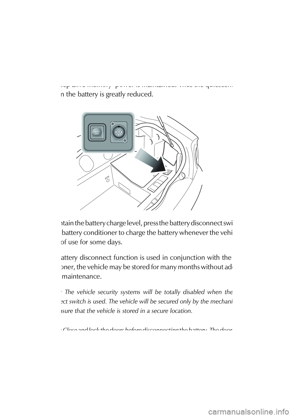
The battery disconnect switch is located in the R/H side wall trim panel of
the boot. When actuated, power to all control modules is disconnected and
only ‘keep alive memory’ power is maintained. Thus the quiescent power
drain on the battery is greatly reduced.
To maintain the battery charge level, press the battery disconnect switch and
use the battery conditioner to charge the battery whenever the vehicle is to
be out of use for some days.
If the battery disconnect function is used in conjunction with the battery
conditioner, the vehicle may be stored for many months without additional
battery maintenance.
Caution: The vehicle security systems will be totally disabled when the battery
disconnect switch is used. The vehicle will be secured only by the mechanical door
locks. Ensure that the vehicle is stored in a secure location.
Caution: Close and lock the doors before disconnecting the battery. The door window
seals will be damaged if the door is closed or opened when the battery is disconnected.
Page 142 of 279

F - Owner Maintenance
1-F-33
Battery Conditioner
The automatic battery conditioner supplied with DB AR1 is suitable for use
on all types of 12 volt lead acid batteries. The conditioner also allows
charging of maintenance free and 12V gel type batteries.
The conditioner has an inbuilt mains connector appropriate for the market
in which the vehicle is sold.
The conditioner output is 13.8V - 14.7V, up to 4.0A. It is designed for
conditioning of partially or fully charged batteries. It will not effectively
charge a completely discharged battery and is not a substitute for a
dedicated battery charger.
WARNINGS:
For indoor use only.
Disconnect the mains supply before making or breaking battery conditioner
connections.
Explosive gasses are given off by batteries during charging. Prevent flames and
sparks - No smoking.
Do not attempt to start the vehicle with the charger connected to the mains
supply.
The unit has an electronic controller which senses when the battery charge level
becomes low and commences charging.
When the battery charge level rises to 80%, a 2 hour timer starts. The unit
continues charging for a further 2 hours until the battery is 100% charged and
then reduces the charge voltage to 13.8 volts to maintain a small trickle charge
to keep the battery in a fully charged state. The conditioner may be left in this state
indefinitely.
Page 143 of 279

F - Owner Maintenance
1-F-34
Battery Conditioner Operation
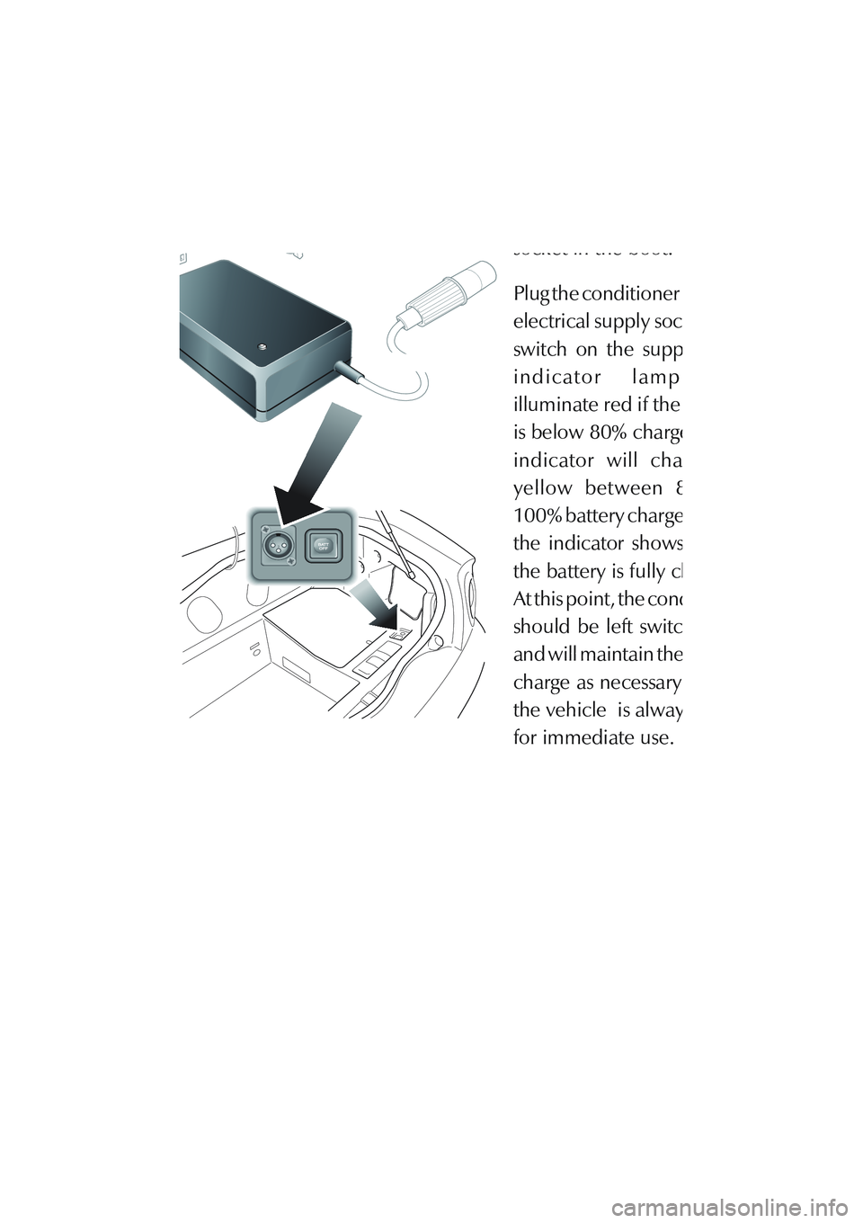
Connect the black output
connector to the vehicle
socket in the boot.
Plug the conditioner into the
electrical supply socket and
switch on the supply. The
indicator lamp will
illuminate red if the battery
is below 80% charged. The
indicator will change to
yellow between 80 and
100% battery charge. When
the indicator shows green,
the battery is fully charged.
At this point, the conditioner
should be left switched on
and will maintain the battery
charge as necessary so that
the vehicle is always ready
for immediate use.
Page 144 of 279

F - Owner Maintenance
1-F-35
The Battery Reconnect Switch
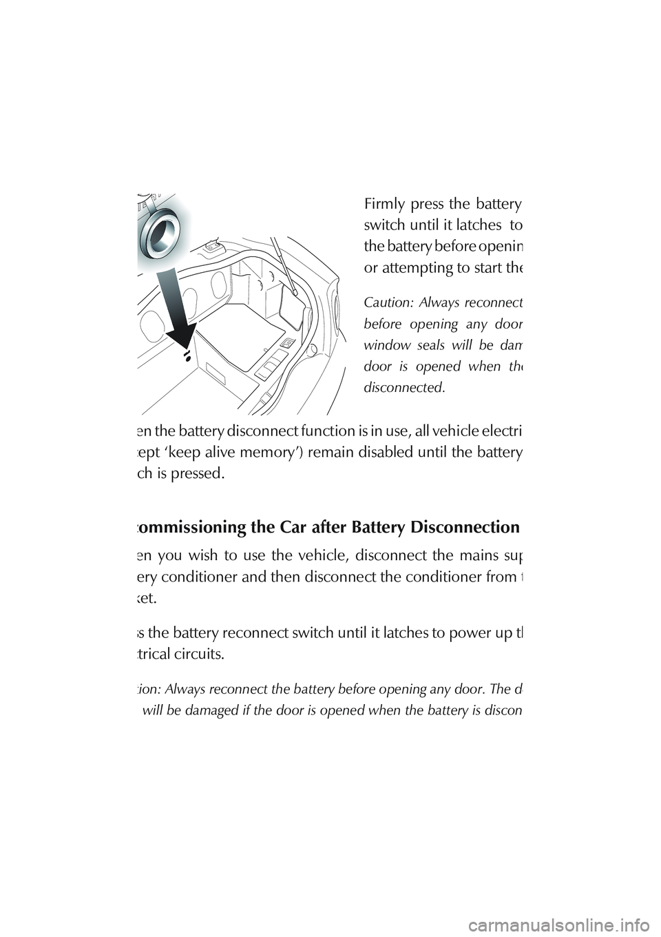
The battery reconnect switch is
located in front wall of the boot.
Firmly press the battery reconnect
switch until it latches to reconnect
the battery before opening the doors
or attempting to start the vehicle.
Caution: Always reconnect the battery
before opening any door. The door
window seals will be damaged if the
door is opened when the battery is
disconnected.
When the battery disconnect function is in use, all vehicle electrical systems
(except ‘keep alive memory’) remain disabled until the battery reconnect
switch is pressed.
Recommissioning the Car after Battery Disconnection
When you wish to use the vehicle, disconnect the mains supply to the
battery conditioner and then disconnect the conditioner from the vehicle
socket.
Press the battery reconnect switch until it latches to power up the vehicles
electrical circuits.
Caution: Always reconnect the battery before opening any door. The door window
seals will be damaged if the door is opened when the battery is disconnected.
Start and run the vehicle as described in the 'Driving' section.
Page 145 of 279

F - Owner Maintenance
1-F-36
Electrical Start from Another Vehicle
If your DB AR1 will not start due to a discharged battery, it may be started
by connecting the battery from another vehicle to the discharged battery.
Before the vehicle is started in this way, ensure that the donor vehicle has
a 12 volt battery and negative (-), black earth terminal to ensure that the
correct battery polarity is maintained.
WARNING: If the voltage or earth of the donor vehicle is different or not known,
do not attempt starting in the way described.
1. Position the vehicles so that the connecting cable will reach between
the batteries. Ensure that the vehicles do not touch each other.
2. To lessen the risk of an electrical short circuit, remove rings, metal
watch bands and any other jewellery. Wear eye protection when
working near the battery. Turn off all electrical motors and ancillaries
in both vehicles. Switch off all lights except those needed to protect the
vehicles or illuminate the work area. Switch off the ignition and apply
the handbrake.
3. Lift out the boot floor panels to gain access to the battery.
4. Connect the red (+) cable between the red (+) positive terminal of the
two batteries.
5. Connect the black (-) cable between the black (-) negative terminals of
the two batteries.
6. Start the donor vehicle engine and run at about 1500 - 2000 rpm.
7. Start the engine. Allow the engine to run for some minutes until the flat
battery is partially charged. Switch off both vehicles.
Page 146 of 279

F - Owner Maintenance
1-F-37 8. Remove the black (-) negative cable from both batteries and then
remove the red (+) positive cable from both batteries.
9. Refit the boot floor panels and close the boot.
10. Restart the engine and take it for a long road run if possible to recharge
the battery.
11. If necessary, recharge the battery using an appropriate 'trickle' charger.
Page 147 of 279

F - Owner Maintenance
1-F-38
Fuse Boxes
Three fuse/relay boxes are fitted to DB AR1 containing the fuses to protect
electrical and electronic systems of the vehicle. The box locations are
indicated on the diagram above.
The forward left and right fuse boxes are located beneath a plate in the
passenger side footwell. The rear fuse box is located in the boot, close to the
battery.
WARNING: Do not add to or alter the electrical systems of DB AR1 unless fitting
Aston Martin approved options to the manufacturers instructions. Use of
unapproved components, incorrect dismantling, incorrect reassembly or incorrect
replacement of components may create electrical overloads and a fire risk.
WARNING: Do not attempt to repair a blown fuse. This could cause a fire hazard
or serious damage elsewhere in the electrical circuits.
WARNING: Do not install a fuse which exceeds the amperage for each location
listed on the following fuse charts.
Page 148 of 279

F - Owner Maintenance
1-F-39
Fuse Lists
Passenger Footwell Fusebox - Right Hand
F1 5A Passive Anti-Theft Module
F2 20A Cigar Lighter
F3 10A Diagnostic Sockets, Radio, Air Conditioning, Driver's
Door Mirror and Window
F4 5A Seat Switches and Heaters
F5 10A Indicator Flasher
F6 10A Ignition Coils 1-6
F7 10A Interior Lamp Cluster
F8 10A Ignition Coils 7-12
F9 20A RHS Seat Heater Relay, RHS Seat Module
F10 10A Dimmer, Passive Anti-Theft Module, Radio
F11 10A Door Mirrors
F12 5A Diagnostic Sockets
F13 25A Not used
F14 10A Hazard Flasher Unit
F15 20A Wiper Logic Module and Wiper Stalk
F16 30A ABS Control Unit
F17 20A Wiper Motor, Logic Module and Wiper Stalk
F18 30A ABS Control Unit
F19 10A Air Conditioning LH Blower Motor
F20 5A Gearshift Interlock Module, Traction Control Switch,
Interior, Map & Courtesy Lamps
F21 10A Air Conditioning RH Blower Motor
F22 10A Powertrain and Transmission control Modules - Keep
Alive Memory
Page 149 of 279

F - Owner Maintenance
1-F-40
Passenger Footwell Fusebox - Left Hand
F1 15A Accessory Terminal
F2 10A Transmission Control Module, Gearshift Interlock
Module, PRND Switch
F3 5A Headlamp Relay, Instrument Pack, Dimmer Unit
F4 10A Multi Function Unit, Air-Conditioning In-Car Sensor,
Anti-Lock Brakes Control Unit
F5 5A Traction Control Switch, Alternator Regulator, Heated
Front Screen Control
F6 10A Rear Fog Switch, RH Dip Beam
F7 30A Starter Relay
F8 10A LH Dip Beam
F9 20A LHS Seat Heater Relay, LHS Seat Module
F10 40A Heated Front Screen Controller
F11 10A RH Horn
F12 30A LH Rad Cooling Fan
F13 10A LH Horn
F14 30A RH Rad Cooling Fan
F15 30A Primary Powertrain Control Module RHS
F16 10A Multi-Function Unit, Central Locking Module, Air
Conditioning Control Panel, Alarm Sounder
F17 30A Secondary Powertrain Control Module LHS
F18 5A Interior Map Lights, Instrument Pack,
RH Rad Module
F19 10A RH Main Beam
F20 20A Window Lift Cut Out, Accessory Terminal,
Air Conditioning Clutch Relay
F21 10A Instrument Pack, LH Main Beam
F22 25A Front Fog Relay
Page 150 of 279

F - Owner Maintenance
1-F-41 Boot Fusebox
F1 10A Reverse Light Relay
F2 20A Security System & Tilt Sensors
F3 5A +12V Ignition
F4 5A Boot Switch Logic Relay, Security System Control Unit
F5 30A Accessory Terminal
F6 5A RH Fog Lamp, Powertrain Control Modules
F7 20A Fuel Pump 2, Secondary Powertrain Control Module
F8 10A HM Stop Light, LH Stop Light
F9 10A Boot Lamps, Radio Aerial Motor
F10 10A Accessory Socket
F11 20A Not Used
F12 20A Not Used
F13 10A Airbag Control Unit
F14 30A Not Used
F15 20A Fuel Pump 1, Primary Powertrain Control Module
F16 10A Rear Fog Light Relay
F17 10A Manual Gearbox Cooling Pump
F18 10A Accessory Terminal
F19 10A RH Tail, Side, Side Marker and
Number Plate Lamps
F20 20A Premium ICE Amplifier
F21 10A LH Tail, Side, Side Marker and
Number Plate Lamps
F22 20A Manual - Exhaust By-pass System
Automatic - Not Used