boot ASTON MARTIN DB AR1 Q 2003 Owners Guide
[x] Cancel search | Manufacturer: ASTON MARTIN, Model Year: 2003, Model line: DB AR1 Q, Model: ASTON MARTIN DB AR1 Q 2003Pages: 279, PDF Size: 3.77 MB
Page 104 of 279

E - Security Systems
1-E-5
Full Alarm Activation
When activated, the siren sounds for 30 seconds (in markets where audible
sirens are permitted) and the direction indicators flash (in markets where
visible alarm signals are permitted). After 5 minutes the alarm stops (i.e. the
direction indicators stop flashing) and returns to the armed state. The doors,
boot and filler flap remain locked throughout.
The alarm can be deactivated by pressing the left (Key) button on the key
fob. This will also disarm the alarm and unlock the doors and filler flap.
Panic Alarm
The system has a panic alarm feature which can be activated whatever the
alarm state. This feature may be used to discourage offenders when you are
either inside the car or within the operating range of the alarm key fob
(approximately 10 metres / 30 feet).
To activate the panic alarm, press and hold the left key fob button for at least
three seconds. The system will enter the full alarm state.
Press the key fob left button again to stop the panic alarm and return to the
state prior to initial panic alarm activation.
If the panic alarm is not switched off using the left button, the siren will stop
after 30 seconds and the indicator flashing will deactivate after 5 minutes.
Page 105 of 279

E - Security Systems
1-E-6
Boot (Trunk) Lock Control
To open the boot (trunk), press the right
key fob button. The key fob red lamp will
stay on so long as the right hand button is
pressed. The direction indicators will flash
once (in markets where visible alarm signals
are permitted), the siren will chirp once (in
markets where audible sirens are permitted
and programmed) and the boot will unlock.
It is not necessary to disarm the alarm in
order to use the boot unlock feature.
Caution: Always ensure that the boot (trunk) lid is securely closed after use. The boot
(trunk) interior lights will be on when the lid is left partially open and will cause the
vehicle battery to discharge.
Page 106 of 279

E - Security Systems
1-E-7
The Passive Anti-Theft System (PATs)
The PATs system is a fully automatic engine immobiliser. The system consists
of a transponder inside the head of each ignition key and, around the
ignition lock, a transceiver aerial which communicates signals to the PATs
electronic control unit. The PATs control unit communicates with the engine
management controller to immobilise the engine until a valid code signal is
received from the ignition key.
Two coded keys are provided with the vehicle. These
keys fit both the door locks, the boot lock and the ignition
lock.
In the event of loss of one of the keys, duplicate keys can
be created and programmed from the other key by your
Aston Martin dealer.
Starting the Engine
When the alarm system is disarmed and the vehicle key is turned in the
ignition lock, the PATs controller sends a signal to the ignition key. The
ignition key must respond with a valid code before engine start will be
enabled. If a valid code is received, the ignition system will operate
normally.
If the key code is not received, or is invalid, engine start remains disabled.
Caution: To ensure a trouble-free signal exchange between the key and the vehicle,
do not cover the key head with any metal object (e.g. another key).
ASTON MARTIN
Page 108 of 279

E - Security Systems
1-E-9
Alarm On
System Armed
Normal state - parked and locked
Alarm Off
System Disarmed
Normal state when driving
Press Left Button Once
Indicators flash
three times
(where permitted and
programmed).
Doors Unlock
Panic Alarm
Siren On for 30 secs
Indicators Flash
5 minutes
Panic Alarm
Siren On for 30 secs
Indicators Flash
5 minutes
Resets after
5 minutesPress Left Button
for 3 seconds
Press Right Button
1indicator flash
1 siren chirp
(where permitted
and programmed).
Boot unlocks
Press Right Button
1 indicator flash
1 siren chirp
(where permitted
and programmed).
Boot unlocks
Boot Open
Press Left Button Once
Indicators flash
once
(where permitted and
programmed).
Doors Lock
Resets after
5 minutes
Press Left Button
for 3 seconds
Alarm System - Operating Summary
Note: Siren and indicator lamp flashes are prohibited in some markets.
Page 127 of 279

F - Owner Maintenance
1-F-18
The Vehicle Toolkit
On vehicles fitted with a space-saver spare wheel , the tool kit is stored in
the spare wheel insert.
On vehicles without the spare wheel option the vehicle toolkit is stored in
a well within the boot floor and covered by a boot floor liner panel. The
standard toolkit consists of the following items:
• 2 Tyre Inflation Aerosols and Warning Labels
• 1 Tyre Pressure Gauge
• 1 Towing Eye
• 1 Pair of Pliers
• 1 Screwdriver
• 1 Pair of Gloves
• 1 Locking Wheelnut Socket (UK only)
• 1 Bulb and Fuse Kit
• 1 Allen Key
Lift up the boot floor to access the toolkit.
Page 131 of 279

F - Owner Maintenance
1-F-22
Jacking and Wheel Changing
WARNINGS:
The front road wheels must be in the straight ahead position before removal. The
front tyre will catch on the wheel arch during removal if not in the "straight
ahead" position.
Check that the temporarily repaired tyre is inflated to the specified pressure.
Never exceed 50 km/h (30 mph) when a temporarily repaired wheel is fitted.
Ensure that no persons are in the vehicle before jacking commences.
Ensure that the handbrake (parking brake) is set and that the car is in 'Park' (Auto)
or 1st Gear (Manual).
Ensure that the vehicle is parked on firm and level ground to ensure a secure base
for the jack.
Do not run the engine while the car is on the jack and never let anyone work
under the car whilst it is on the jack.
Spare Wheel Access (where fitted)
On vehicles with the space saver spare
wheel, the spare wheel is stored in a
well in the boot floor.
Lift out the boot floor and toolkit.
Remove the spare wheel retaining screw
and lift out the spare wheel.
Page 133 of 279

F - Owner Maintenance
1-F-24
5. Using the handwheel (A) on the jack screwshaft, raise the jack until the
jack top plate (B) fits to the jacking point stud under the sill at the affected
wheel. Ensure that the jack baseplate is squarely seated on solid ground.
Note: In the following step, the jack handle extension (D) must be used to prevent
damage to the vehicle paintwork as the jack handle (C) is rotated.
6. Ensure the safety of any persons in the vicinity and the security of the
wheel chock. Raise the vehicle as necessary using the jack ratchet handle
(C) and extension (D) to lift the deflated wheel clear of the ground.
Remove the wheel nuts and remove the deflated wheel.
7. Mount the spare wheel on the hub. Reverse the jack ratchet handle on
the extension and partially tighten the wheel nuts.
8. Lower the vehicle to the ground. Tighten the wheel nuts alternately.
Remove the wheel chock.
9. Repack the tools into their location in the boot. Place the defective wheel
into the bag provided and place on the rear seats.
10. When the spare wheel is correctly fitted and secured, drive conservatively
(80 km/h (50 mph) maximum) and have the wheel nuts torque tightened
to 88-102 Nm (65-75 lbs/ft) at the earliest opportunity.
WARNINGS:
Follow the wheel label warnings. Failure to comply can be dangerous. Drive
cautiously and refit a serviceable standard wheel and tyre as soon as possible.
Never fit more than one temporary spare wheel at a time.
Check that the temporary spare tyre is inflated to the specified pressure.
Never exceed 80 km/h (50 mph) when the spare wheel is fitted.
Page 139 of 279

F - Owner Maintenance
1-F-30
Electrics
Battery
The battery is located in the right-hand side of the boot. The battery is
maintenance free and should only require checking by your dealer during
regular vehicle services.
Battery charge level must be maintained by use of the battery conditioner
if the vehicle is not in frequent use.
Caution: The engine must never be run with the battery disconnected.
WARNING: The battery emits combustible gas (hydrogen) when charging. Avoid
sparks and short circuits by switching off the charger before connecting or
disconnecting the charger at the battery.
Battery posts, terminals and related accessories contain lead and lead compounds.
Wash hands after handling.
Page 141 of 279

F - Owner Maintenance
1-F-32
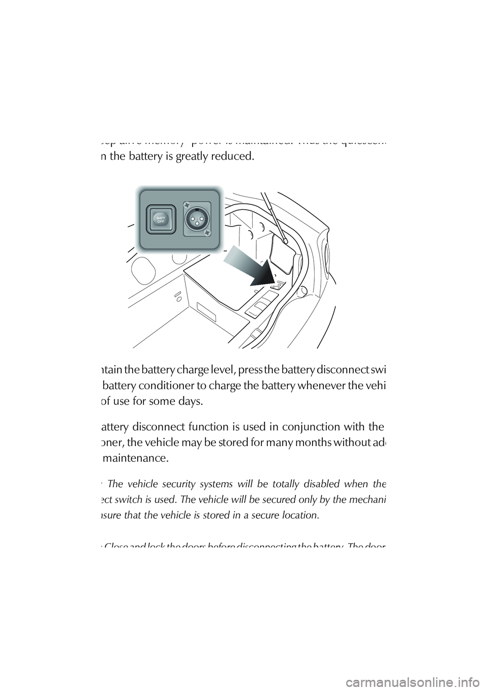
The Battery Disconnect Switch
The battery disconnect switch is located in the R/H side wall trim panel of
the boot. When actuated, power to all control modules is disconnected and
only ‘keep alive memory’ power is maintained. Thus the quiescent power
drain on the battery is greatly reduced.
To maintain the battery charge level, press the battery disconnect switch and
use the battery conditioner to charge the battery whenever the vehicle is to
be out of use for some days.
If the battery disconnect function is used in conjunction with the battery
conditioner, the vehicle may be stored for many months without additional
battery maintenance.
Caution: The vehicle security systems will be totally disabled when the battery
disconnect switch is used. The vehicle will be secured only by the mechanical door
locks. Ensure that the vehicle is stored in a secure location.
Caution: Close and lock the doors before disconnecting the battery. The door window
seals will be damaged if the door is closed or opened when the battery is disconnected.
Page 143 of 279

F - Owner Maintenance
1-F-34
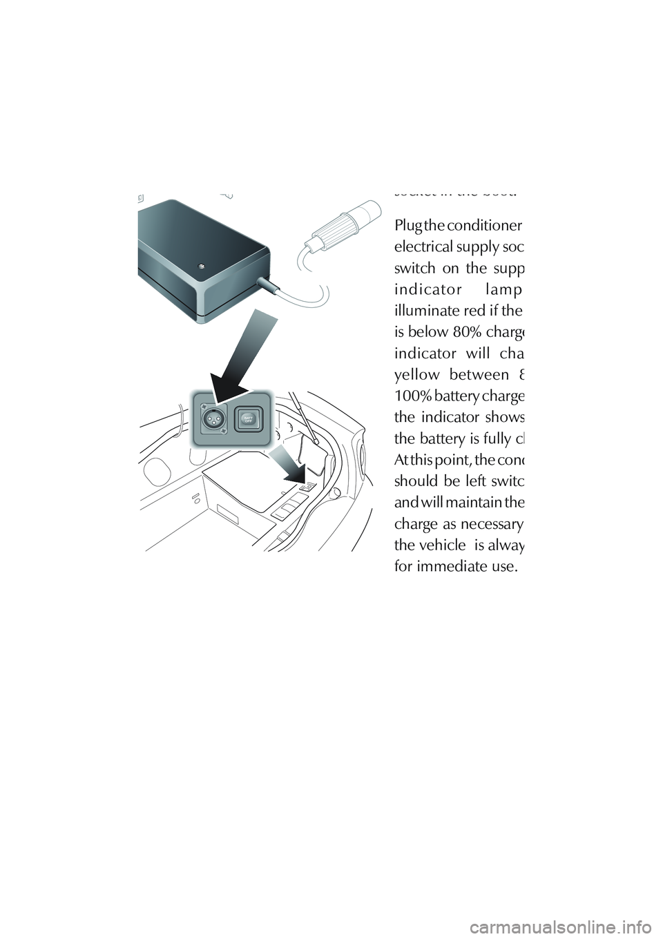
Battery Conditioner Operation
Connect the black output
connector to the vehicle
socket in the boot.
Plug the conditioner into the
electrical supply socket and
switch on the supply. The
indicator lamp will
illuminate red if the battery
is below 80% charged. The
indicator will change to
yellow between 80 and
100% battery charge. When
the indicator shows green,
the battery is fully charged.
At this point, the conditioner
should be left switched on
and will maintain the battery
charge as necessary so that
the vehicle is always ready
for immediate use.