ECO mode ASTON MARTIN DB7 1997 User Guide
[x] Cancel search | Manufacturer: ASTON MARTIN, Model Year: 1997, Model line: DB7, Model: ASTON MARTIN DB7 1997Pages: 421, PDF Size: 9.31 MB
Page 326 of 421
^2?
Air Conditioning
System Recharging / Compressor Oil Check
Recharging the System
1.
Open the high side valve on the unit control panel.
If the messages PROGRAM and CHARGE are not
displayed press the CHG key to enter PROGRAM
mode.
2.
Key in the amount of refrigerant needed to recharge
the system and press ENTER.
3. Press the CHG key; the message AUTOMATIC and
the entered amount of refrigerant wi
11
be displayed.
The display counts down to zero as the charging
process proceeds. When the charging is complete
the message CPL is displayed.
If the refrigerant transfer is too slow the charging
unit emits a signal. If the message CHECK
REFRIGERANT is not displayed, close the high side
valve,
open the low side valve and start the air
conditioning system to pull the remainder of the
charge into the system.
If the refrigerant transfer will not complete and the
message CHECK REFRIGERANT is displayed, press
the HOLD/CONT key to interrupt the cycle then
reset the unit by pressing the RESET key. Recover
the refrigerant already charged into the system by
following the procedure for recovering the
refrigerant, add new refrigerant to the tank and
return to Step 1 to recharge the system.
4.
If the air conditioning system is not running start it
and let it run until the gauge pressure readings
stabilize (compare the gauge readings with the
system manufacturer's specifications).
Note:
Ensure
that the
readings
are accurate by closing
both the high and low side
valves
on the unit's control
panel.
5. Check the evaporator outlet temperature to make
sure that the air conditioning system is operating
properly (refer to the system manufacturer's
specifications for the proper temperature).
Compressor Oil Checic
Data
Special Tools
Sanden oil dipstick JD 149
Torque Figures
Oil filler plug 8-12 Nm
Procedure
Whenever a component has been replaced in the
refrigerator system or there is an obvious oil leak, the
following procedure should be carried out.
A Sanden oil dipstick and angle gauge are required in
order to carry out the check.
1.
Run the compressor for 10 minutes at engine idle
speed.
2.
Depressurise the system.
3. Lay the angle gauge across the flat surfaces of the
two front mounting lobes. Centre the bubble and
note the mounting angle.
4.
Remove the compressor from the vehicle.
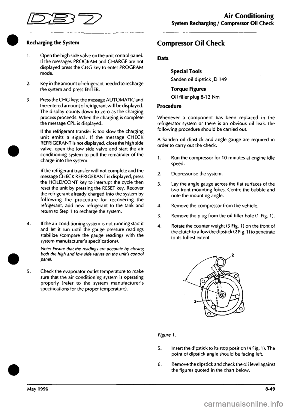
3. Remove the plug from the oil filler hole
(1
Fig. 1).
4.
Rotate the counter weight (3 Fig. 1) on the front of
theclutchtoallowthedipstick(2 Fig. 1)to penetrate
to its fullest extent.
Figure 1.
5. Insert the dipstick to its stop position (4 Fig. 1). The
point of dipstick angle should be facing left.
6. Removethedipstickandchecktheoil levelagainst
the figures quoted in the chart below.
May 1996 8-49
Page 383 of 421
The Aston Martin Lagonda Diagnostic System
Users Guide "^7
Establishing Communications
when cable connections are completed, switch on the
vehicle ignition. The electronic control units will 'wake
up'
and communication between the selected control unit
and the PDU will be established.
As communication
is
established with the selected system,
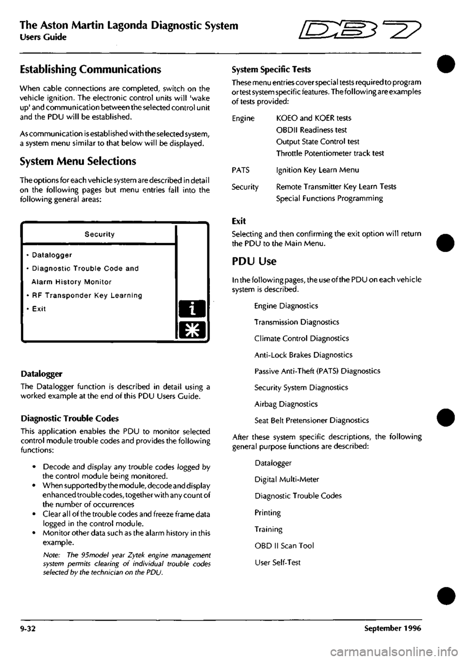
a system menu similar to that below will be displayed.
System Menu Selections
The options for each vehicle system are described in detai
I
on the following pages but menu entries fall into the
following general areas:
Security
• Datalogger
• Diagnostic Trouble Code and
Alarm History Monitor
• RF Transponder Key Learning
• Exit a
o
Datalogger
The Datalogger function is described in detail using a
worked example at the end of this PDU Users Guide.
Diagnostic Trouble Codes
This application enables the PDU to monitor selected
control module trouble codes and provides the following
functions:
• Decode and display any trouble codes logged by
the control module being monitored.
• When supported by the module, decodeand display
enhanced trouble
codes,
together with any count of
the number of occurrences
• Clear all of the trouble codes and freeze frame data
logged in the control module.
• Monitor other data such as the alarm history in this
example.
Note: The 95model year Zytek engine management
system permits clearing of individual trouble codes
selected by the technician on the PDU.
System Specific Tests
These menu entries cover special tests required to program
ortest system specificfeatures. The following are examples
of tests provided:
Engine KOEO and KOER tests
OBDII Readiness test
Output State Control test
Throttle Potentiometer track test
Ignition Key Learn Menu
Remote Transmitter Key Learn Tests
Special Functions Programming
PATS
Security
Exit
Selecting and then confirming the exit option will return
the PDU to the Main Menu.
PDU Use
In the following
pages,
the use of the PDU on each vehicle
system is described.
Engine Diagnostics
Transmission Diagnostics
Climate Control Diagnostics
Anti-Lock Brakes Diagnostics
Passive Anti-Theft (PATS) Diagnostics
Security System Diagnostics
Airbag Diagnostics
Seat Belt Pretensioner Diagnostics
After these system specific descriptions, the following
general purpose functions are described:
Datalogger
Digital Multi-Meter
Diagnostic Trouble Codes
Printing
Training
OBD II Scan Tool
User Self-Test
9-32 September 1996
Page 387 of 421
The Aston Martin Lagonda Diagnostic System
Users Guide ffi:S5'=2?
Engine Datalogger
The datalogger software is designed to aid the technician in identifying permanent or intermittent faults in the DB7's
electrical and electronic systems. It can provide a recorded view of selected signals over a chosen time period. This
recording may be captured in a static, rolling road or road test situation. Data recorded during such tests may then be
analysed on completion of the test or printed out for later analysis.
Datalogger operation is described using a fully worked example at the end of this PDU Users Guide.
The full list of datalogger signal names and descriptions is provided in the DB7 OBDII Diagnostic Manual and on the PDU
screen.
The following list is a summary of the PCM signals which may be monitored.
Signal Description
ACCS Air-Con Control Switch - 1 = A/C On
ACP Air-Con Pressure Sensor - 1 = A/C pressure high
ACT MAX Maximum Intake Air Temperature signal during normal running
Adap Fuel 1 Current Adaptive Fuel Correction - (% of range)
Adap Fuel 2 Current Adaptive Fuel Correction - (% of range)
ADPT1F Adaptive Fuel - Table 1 failure mode
ADPT2F Adaptive Fuel - Table 2 failure mode
AIR Air Pump On/Off - 1 = Pump On
AIRM Air Pump Monitor -1 =
high,
pump on
B+ Battery Positive - Volts
BARO Barometric Pressure
CID Cylinder Identification - Cam sensor status
CMP STAT Cam Position Sensor -1 = CID mis, not currently reliable
DRVCNT Number of OBDll Drive Cycles Completed
DSDRPM Desired engine speed (RPM)
DTCCNT Diagnostic Trouiale Codes Count (Fault codes + pending codes. MIL and non-MIL)
ECT MAX Maximum Engine Coolant Temperature signal during normal running
ECT STAT Engine Coolant Temperature - in or out of range
ECT-C Engine Coolant Temperature - "C or raw counts
ECT-V Engine Coolant Temperature - Volts or raw counts
EGR STAT EVP EGR sensor failure
ENGLOAD Engine Load (Ratio of air charge over standard)
ENGRPM Engine Speed - RPM
EPT DPFE Sensor feedback
EVAP DC Cannister Purge Duty Cycle (% on)
EVAPCVA Vapour Management Valve (VMV) fault detected
Evts HI Cumulative cylinder events total carried over from previous background logic executions
Evts LO Cumulative cylinder events total carried over from previous background logic executions
FPM Fuel Pump Monitor - 0 = pump off, 1 = pump on
FPUMP DC Desired Fuel Pump Duty Cycle - 0% or 100%
H02S12 Sensor Output - Volts
H02S21 Sensor Output - Volts
H02S22 Sensor Output - Volts
H02S1I Sensor Output - Volts
HFC High Speed Fan Status
Htrl
1
ret Highest number of retries seen on the H02S 11 heater
Htrl 2 ret Highest number of retries seen on the H02S 12 heater
Htr21 ret Highest number of retries seen on the H02S 21 heater
Htr22 ret Highest number of retries seen on the H02S 22 heater
HTRCM11 H02S n heater current
HTRCM12 H02S 12 heater current
HTRCM21 H02S 21 heater current
HTRCM22 H02S 22 heater current
9-36 September 1996
Page 391 of 421
The Aston Martin Lagonda Diagnostic System
Users Guide ^=2?
Transmission Diagnostics
Automatic transmission DB7s are fitted with a GM4L80-
E gearbox electronically controlled by a Transmission
Control Unit (TCM)
The TCM is mounted on the rear left wheel
arch.
It may be
electronically accessed from the upper diagnostic socket.
The TCM continuously monitors requests made by the
driver via the gear selector, throttle pedal, mode switch,
etc. This data is used in conjunction with speed input from
the transmission unit to calculate the optimum shift points
undercurrentconditions.Shiftpressureand ignition retard
are also controlled from this data to enhance shift quality
and reduce transmission wear.
TheTCM also detects faults within the transmission system
and stores the relevant fault codes for later analysis.
Gearshifts are controlled by two solenoid valves and a
pressure regulator within the transmission valve block
assembly.
If a serious fault occurs, the TCM removes all electrical
power from these valves and the transmission defaults to
a 'limp home' condition. In this state, only mechanical
selection of either reverse or second gear is available.
Gearshift Timing
Inputs from the performance mode switch (Sport, Normal
or 1st Gear Inhibit) and the throttle position sensor are
used to modify transmission gearshift operation
as
required
by the driver.
Sport mode raises the roadspeed at which gearshifts occur
enabling higher acceleration rates for the vehicle.
1st gear inhibit prevents engagement of first gear to reduce
the risk of wheel slip in icy conditions.
The throttle position sensor signal is continuously
monitored by the TCM to detect a rapid throttle opening.
If the throttle position sensor signal rises rapidly to above
4.5 volts, a 'Kickdown' condition is initiated. In this
condition,
upshifts are delayed to higher road speeds to
provide the higher acceleration required for overtaking
etc.
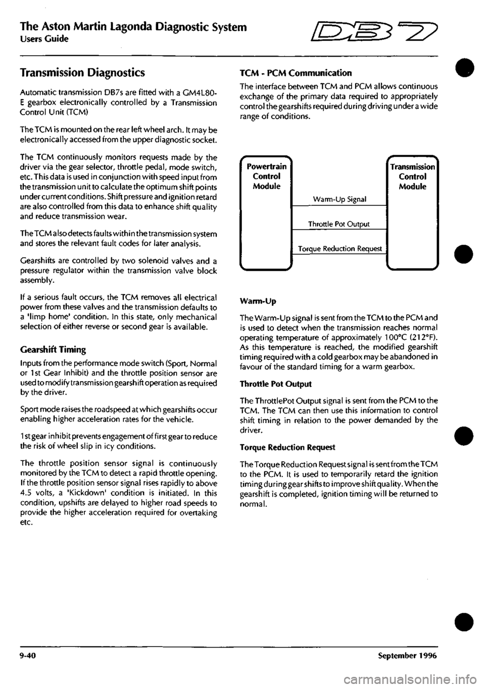
TCM - PCM Communication
The interface between TCM and PCM allows continuous
exchange of the primary data required to appropriately
control the gearshifts required during driving under
a
wide
range of conditions.
Powertrain
Control
Module
^.. ^
Warm-Up Signal
Throttle Pot Output
Torque Reduction Request
^ •- -^ Transmission
Control
Module
Warm-Up
The Warm-Up signal is sent from the TCM to the PCM and
is used to detect when the transmission reaches normal
operating temperature of approximately 100°C (212"'F).
As this temperature is reached, the modified gearshift
timing required with a cold gearbox may be abandoned in
favour of the standard timing for a warm gearbox.
Throttle Pot Output
The ThrottlePot Output signal is sent from the PCM to the
TCM.
The TCM can then use this information to control
shift timing in relation to the power demanded by the
driver.
Torque Reduction Request
The Torque Reduction Requestsignai
is
sent from the TCM
to the PCM. it is used to temporarily retard the ignition
timing during gear shifts to improve shift quality. When the
gearshift is completed, ignition timing will be returned to
normal.
9-40 September 1996
Page 393 of 421
The Aston Martin Lagonda Diagnostic System
Users Guide ^7
TCCS Torque Convertor Clutch Solenoid
The torque converter clutch solenoid is mounted on the
valve body. The signal is Pulse Width Modulated at 32Hz
to provide closed loop control of the pressure across the
converter clutch plates. 1 bit = 0.39% Range 0 to 100%
TP Throttle Position
This is provided by the EECV Engine Management System
as a Pulse Width Modulated signal derived from the
throttle position signal read by that module from the
throttle position sensor.
TCS Torque Convertor Slip
Torque converter slip is defined
as
the difference between
the Input/turbine (ni) speed and the Engine speed (Ne):
Slip = Ne-Ni. The PWM duty cycle may increase from 0
to 100% when TCC is fully applied. In practice a 100%
duty cycle will be achieved only if
a
large slip is detected.
Normal ly only a 50 to 95% duty cycle will be required for
full application of the TCC. Slip is expressed in rpm. 1 Bit
- 1/8 rpm. Range -4096 to +4096 rpm.
TCSW Transmission Control Switch
A three position switch allows the driver to select Sport,
Normal or 1st Gear Inhibit mode. When 'Sport' is selected
gearshifts take place at higher engine revs. When '1st
Gear Inhibit' is selected, the transmission only operates in
the higher forward ratios to prevent wheel slip in icy
conditions.
TISSA Turbine Input Shaft Speed
Turbine speed is the speed of the input shaft of the
transmission measured by the input speed sensor mounted
on the transmission. An alternating waveform is induced
in the sensor by 31 serrations on the forward clutch
housing as it rotates. The waveform frequency and
amplitude is low at low speeds and high at high speeds.
The TCM changes this signal into a digital signal. 1 bit =
1/8 RPM. Range: 0 - 8192 RPM.
TOS+ Transmission Output Speed
The output speed sensor is mounted on the transmission
case and measures the speed of the output shaft. As the
shaft rotates an alternating waveform is induced in the
sensor which varies in frequency and voltage. The wave
form is converted into
a
digital signal by the TCM and used
to control TCC, line pressure, shift timing and torque
management. 1 bit = 1/8 RPM. Range 0-8192 RPM
TRX Transmission Control Switch X
TRY Transmission Control Switch Y
TRZ Transmission Control Switch Z
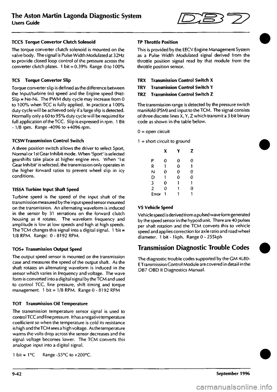
The transmission range is detected by the pressure switch
manifold (PSM) and input to the
TCM.
The signal consists
of three discrete lines X, Y, Z which transmit a 3 bit binary
code as shown in the table below.
0 = open circuit
1 = short circuit to ground
X Y Z
p
R
N
D
3
2
Error
0
1
0
1
0
0
1
0
0
0
0
1
1
1
0
1
0
0
1
0
1
VS Vehicle Speed
Veh icie speed
is
derived from
a pu Ised
wave form generated
by the speed sensor in the hypoid unit. There are 40 pulses
per shaft rotation and the TCM converts this to vehicle
speed and applies correction for axle ratio and road wheel
diameter. 1 bit -
1
kph. Range 0 - 255kph
Transmission Diagnostic Trouble Codes
The diagnostic trouble codes supported by the CM 4L80-
E
Transmission Control Module are covered indetail inthe
DB7 OBD II Diagnostics Manual.
TOT Transmission Oil Temperature
The transmission temperature sensor signal is used to
control TCC and line
pressure.
It
has a
negative temperature
coefficient so when the temperature is cold its resistance
is high and the TCM sees
a
high voltage. Asthe temperature
warms the volts drop across the sensor decreases and the
signal voltage becomes lower. The TCM converts this
analogue input into a digital signal.
1 bit =
1
°C Range -55°C to +200°C.
9-42 September 1996
Page 398 of 421
^^?
The Aston Martin Lagonda Diagnostic System
Users Guide
Seat Belt Pretensioner Diagnostics
(where fitted)
Description
The DB7 seat belt pretensioner system operates the
drivers seat belt pretensioner in conjunction with the
Airbag system. The seat belt pretensioner control
module is located underthe right hand seat, beside the
seat control module.
The pretensioner control module calculates changes
in vehicle speed using an input signal from an
accelerometer. When a collision is detected (Rapid
reduction in vehicle speed) the pretensioner charge is
fired using electrical energy stored in a capacitor
within the pretensioner control module. Firing of the
pretensioner charge applies additional tension to the
drivers seat belt.
The airbag and seat belt pretensioner systems share the
SRS (Airbag) warning lamp. Any fault detected by the
pretensioner control module is indicated by constant
illumination ofthe
SRS
(Airbag) warning
lamp.
Flashing
of the SRS warning lamp indicates a fault in the airbag
system.
Should both systems develop faults, the pretensioner
system will permanently illuminate the warning lamp.
This would mask the airbag system warning indication.
Therefore, rectify the pretensioner fault and then retest
for faults in the airbag system
The pretensioner control module can log up to 10
diagnostic trouble codes together with a time since
each fault was alerted to the driver. Each fault will be
identified as 'Permanent' or 'Intermittent' on the PDU
diagnostic trouble codes screen.
System Connections
The Autoliv RC5 Pretensioner Control Module has an
18 pin connector featuring six shorting bridges. The
mating halves ofthe connector may be securely locked
using a double mechanical locking system.
The following pins on the control module connector
are used in the Aston Martin seat belt pretensioner
system:
Pin 1
Pin 2
Pin n
Pin 12
Pin 14
Pin 15
Case
September 1996
Ground
SRS/Airbag Warning Lamp
Drivers airbag positive
Drivers airbag negative
Serial communications
12 volt positive feed
Ground
System Fault Strategy
No single fault may cause an unexpected deployment.
The controller will supervise the airbag/pretensioner
electrical system in order to warn the driver should a
fault occur. Any fault detected by the self diagnostics
shall cause the airbag warning lamp to be activated,
and in some cases the pretensioner control module to
enter shutdown mode. In shutdown mode, the energy
ofthe reserve capacitors shall be discharged to avoid
unintended deployment.
As the ignition is switched on, the pretensioner
controller will directly discharge theenergy capacitors.
When the start up procedure is completed without
detecting any faults, the converter will be activated
allowing the capacitors to be
charged.
The system shall
be fully active within 11 seconds after switching the
ignition on providing that no faults are detected.
All system faults monitored by the controller are filtered
in software to avoid fault warnings due to transient
electrical disturbances.
If a fault which could lead to inadvertent deployment
bedetectedbythemicroprocessor,asoftwareshutdown
will be generated. However, a leakage to an earth or
positive potential in the pretensioner output circuit
shall not cause the controller to enter shutdown mode.
If
a
permanent short of the ignition transistor occurs, a
shutdown shall be generated by the hardware circuit.
If a shutdown occurs, the system shall be unable to
deploy the pretensioner after a period of
3
seconds (i.e.
capacitors discharged to under minimum deployment
voltage).
WARNING: To avoid the possibility of personal
injury caused by accidental deployment of the
pretensioner, disconnect the vehicle battery and
wait at least 10 minutes for all voltages to fully
discharge before working on the pretensioner
system. This covers the possibility of the normal
capacitor discharge circuits being inopera tive and
failing to discharge the capacitor when instructed
to do so.
If the module enters shutdown mode, all diagnostic
functions are stopped, but the communications link
remains active. A fault code corresponding to the
cause of the problem may be read by the PDU.
9-47
Page 401 of 421
The Aston Martin Lagonda Diagnostic System
Users Guide ^=2?
Printer Use Digital Multimeter
Print Trace
The Trace Buffer is used to record technician use of the
PDU.As the diagnostics are executed, the following
information is written to trace:
Screen Title
Menu options selected
Operator questions selected
Operator actions
Control module information
Test limits and results
P codes detected by the DTC monitor
Snapshot data from the datalogger
OBD II freeze frame data
Set up the printer and load with paper. Select Print
Trace and confirm the selection. All recorded
information in the above list will be printed.
Printtrace is supported in English, French, German and
Italian.
Print Screen
The Print Screen function dumps a bitmap image of the
current screen display to the printer. This function is
particularly useful for recordingdata such as waveforms
captured by the datalogger application.
The print screen function is supported in English,
French,
German, Italian and Japanese.
Introduction
The Digital Multi-Meterprovidesthecapability to measure
voltage, current, resistance, frequency, pulse width, pulse
period and duty cycle using measurement probes or
vehicle interface adaptor channels.
WARNING: DMM measurements must not be taken
while the PDU
is
connected to the
base
station. The PDU
measurement system
becomes
referenced to earth when
connected to the base station. Serious measurement
errors may be present
because
of any voltage difference
between vehicle ground and base station earth. Operation
of the PDU in this mode has both functional and safety
implications and therefore must be
avoided.
A digital multimeter (DMM) is resident within the PDU
software toolbox.
The DMM application can be accessed from the main
menu.
On selection of "Digital Multimeter" from the main
menu,
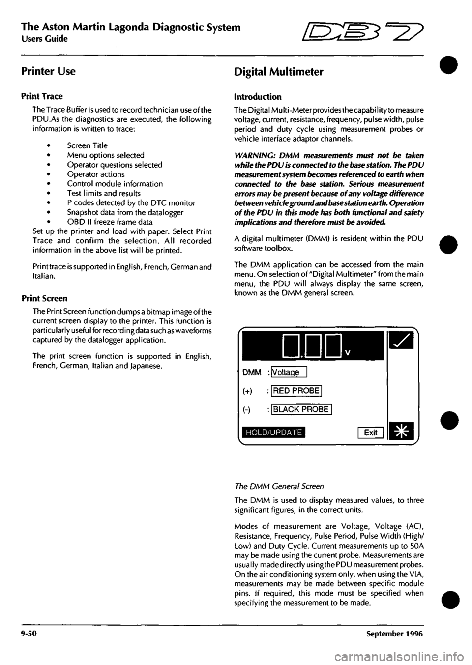
the PDU will always display the same screen,
known as the DMM general screen.
DDD
DMM : Voltage
(+) : RED PROBE
(-) : BLACK PROBE
HOLD/UPDATE Exit
The DMM General Screen
The DMM is used to display measured values, to three
significant figures, in the correct units.
Modes of measurement are Voltage, Voltage (AC),
Resistance, Frequency, Pulse Period, Pulse Width (High/
Low) and Duty Cycle. Current measurements up to 50A
may be made using the current probe. Measurements are
usually madedirectlyusingthe PDU measurement probes.
On the air conditioning system only, when using the VIA,
measurements may be made between specific module
pins.
If required, this mode must be specified when
specifying the measurement to be made.
9-50 September 1996
Page 421 of 421
The Aston Martin Lagonda Diagnostic System
Users Guide [E^M^"^?
System Setup
The System Setup Menu may be accessed at any time
from the asterisk (*)
menu.
The menu provides system
configuration options for the following parameters:
Display Mode
Sets the screen to either Black on White or White on
Black display
Trace Mode
Sets
the trace information gathering to All the Time or
Only After a Fault.
Trace Type
Sets
the trace system to gather Everything or Only Test
Information.
Fault Overide
If fault overide is OFF, the trace recording will stop
when
a
fault
occurs.
With fault overide
set
to
ON,
trace
recording will continue after fault occurence
and
show
vehicle performance after the fault.
Language
Permits selection of one of the following languages:
English
German
French
Italian
Japanese
Caution: Check that the correct
language
is
selected.
If
you
accidentaly select
and confirm the
wrong
language,
it may be difficult to
configure
the system back
to a familiar
language.
9-70 September 1996