ECO mode ASTON MARTIN DB7 1997 Workshop Manual
[x] Cancel search | Manufacturer: ASTON MARTIN, Model Year: 1997, Model line: DB7, Model: ASTON MARTIN DB7 1997Pages: 421, PDF Size: 9.31 MB
Page 186 of 421
Electrics
Airbag System ^^?
Emergency First Aid Procedures
If the airbag is ruptured without deployment and
exposure to the propel lant mixture occurs, observe
the following first-aid treatments:
• Ingestion - Do not induce vomiting and seek
prompt medical attention.
• Skin contact - Immediately wash skin with soap
and water and seek medical attention.
• Eyes - Immediately flush eyes with water for at
least 20 minutes and seek prompt medical
attention.
• Inhalation - Immediately move victim to fresh
air and seek medical attention.
• Physical trauma,
e.g.
burns, abrasions, or impact
due to premature ignition or deployment of the
inflator assembly - Treat symptomatica
I
ly and
seek prompt medical attention.
Safety Procedures
Handling Deployed (Fired) Modules
See 'Emergency First Aid Procedures'
Prevent contact of the inflator with liquids,
combustibles and flammable materials. Failure to
follow these instructions could result in chemical
burns and personal injury.
Ensure that the modules are cool before handling.
After deployment, the airbag surface contains small
deposits of sodium hydroxide which can cause
irritation to the skin and eyes.
When handling deployed airbags, always wear
rubberglovestoBS1651 grade 2 or equivalent, and
chemical resistant goggles to BS 2092 grade 2 or
equivalent.
After handlingdeployed airbags, immediately wash
hands and exposed skin surface areas with mild
soap and water.
Handling Undeployed Damaged Modules
The material inside the module is hermetically
sealed and is completely consumed during
deployment.
No attempt shou
Id
be made to open the modu
le
as
this leads to a risk of exposure to sodium azide.
In the unlikely event of a gas generator being
damaged,
it must be examined by trained personnel
before any attempt is made to remove and/or
deploy.
Full protective clothing must be worn when dealing
with any spillage.
Ruptured units must be stored away from acids,
halogens, heavy metals and metal salts. Damaged
units may produce hydrazoic acid if exposed to
liquids.
Failure to comply with these instructions may result
in fire, noxious fumes and severe personal injury or
death.
Fire Hazard Information
Thermal decomposition or combustion may
produce dense smoke and other dangerous fumes
which infiresituationsformahighlytoxicexplosive.
In the event of a fire, the surrounding area must be
evacuated and all personnel kept well upwind of
the area.
Full fire fighting protective gear and a self contained
breathing apparatus operating in positive pressure
mode must be worn for combating fire. Material
near the fire must be cooled with water spray to
prevent ignition.
Fires should be allowed to burn themselves out if
not threatening to life or property, if fire
is
threatening
to life or property, use copious quantities of water
to extinguish.
Ventilation
Local exhaust ventilation designed by
a
professional
engineer should be provided if vapours, fumes or
dusts are generated whilst working with the airbag
module.
Respiratory Precautions
To prevent the inhalation of dangerous fumes and
dusts,
an approved mask should be worn.
6-70 September 1996
Page 218 of 421
Electrics //—>> ^^^^^^ • >^
Seat Belt Pretensioner I'•—
-"i-t.
^-^
JH—X
System Fault Strategy
No single fault may cause an unexpected deployment. The controller will supervise the pretensioner electrical
system in order to warn the driver should a fault occur. Any fault detected by the self diagnostics shall cause the SRS/
airbag warning lamp to be activated, and in some cases the pretensioner control module to enter shutdown mode.
In shutdown mode, the energy of the reserve capacitors shall be discharged to avoid unintended deployment.
As the ignition is switched on, the pretensioner controller will directly discharge the energy capacitors. When the
start up procedure is completed without detecting any faults, the DC/DC converter will be activated allowing the
capacitors to be charged. The system shall be fully active within
11
secondsafterswitchingthe ignition on providing
that no faults are detected.
All system faults monitored by the controller are filtered in software to avoid fault warnings due to transient electrical
disturbances.
If a fault which could lead to inadvertent deployment is detected by the microprocessor, a software shutdown will
be generated. However, a leakage to an earth or positive potential in the pretensioner output circuit shall not cause
the controller to enter shutdown mode.
If a permanent short of the ignition transistor occurs, a shutdown shall be generated by the hardware circuit. If a
shutdown occurs, the system shall be unable to deploy the pretensioner after a period of 3 seconds (i.e. capacitors
discharged to under minimum deployment voltage).
WARNING: To avoid the possibility of personal injury caused by accidental deployment of the pretensioner,
disconnect the vehicle battery and wait at least 10 minutes for all voltages to fully discharge before working on
the pretensioner
system.
This
covers the possibility of the normal capacitor discharge circuits being inoperative
and failing to discharge the capacitor when instructed to do so.
WA RNING: Do not make any electrical measurements on the pretensioner squib. Electrical measurement devices
can induce sufficient voltage to cause unintentional firing of the pretensioner assembly
If the module enters shutdown mode, all diagnostic functions are stopped, but the communications link remains
active.
A fault code corresponding to the cause of the problem may be read by the PDU.
Assembly/Removal/Service I nstructions
WARNING: In the event of a vehicle impact where the airbags and the seatbelt pretensioner (if fitted) are
deployed, the following actions MUST be performed:
Check the condition of the
seatbelts,
steering wheel, steering column, all connections to airbags, and the column
switchgear connectors for integrity and damage. If in any doubt, replace suspected parts for new parts.
Replace both crash
sensors,
the safing sensor and the seatbelt pretensioner module (if fitted).
On completion of all repair procedures, switch on the ignition and check that the Airbag/SRS warning light
comes
on when the ignition is switched on and extinguishes after approximately six seconds indicating satisfactory
completion of the airbag and pretensioner
system
self
tests.
Vehicles for the North American, Australian and Japanese markets are fitted with drivers seat belt pretensioner
systems and are fitted with a shorting plug in the yellow connector adjacent to the pretensioner control module.
Vehicles for other markets do not have drivers seat belt pretensioners fitted but have a blanking plug in the yellow
connector adjacent to the pretensioner control module.
6-102 September 1996
Page 227 of 421
3-^?
Electrics
Seat Removal/Replacement 97.5 MY
6.6.03
Seat Removal 97.5 MY
Description
The 97.5 MY front seats are common to the DB7
Coupe
and
Volante
models.
Seat
switch
assembi ies
are located on the outboard side of both driver and
passenger
seats.
The front switch controls fore and
aft movement and the seat height adjustment. The
centre switch controls the recline adjustment. The
rear switch
controls
the
lumbar support adjustment.
The seat
heater switches are mounted on the centre
console, forward of the gear selector
lever.
Only one of
the
slide,
recline or height motors can
be driven under manual control at any one time.
Each seat switch pack is hard wired to the relevant
Seat Control
Module
beneath each
seat.
The
module
outputs are hard wired to the seat motors.
Removal
WARNING -
Seat
belt
Pretensioners
(if fitted):
To avoid the possibility
of
personal
injury
caused
by accidental deployment of the seat belt
pretensioner,
disconnect
the
vehicle battery and
wait at
least
10
minutes
for all
voltages
to fully
discharge
before working on the
pretensioner
system.
This covers the possibility
of
the normal
capacitor
discharge
circuits being inoperative and
failing to discharge the detonator capacitor when
instructed
to
do
so.
Procedure
1.
Motortheseatto
its
maximum forward position and
remove the fixings at the rear of the slides.
2.
Motor the seat to its maximum rearward position
and remove the front seat slide fixings.
3. Disconnect the battery
ground
(black)
lead.
Wait at
least 10 minutes for the pretensioner power supply
to fully discharge before working on the seat if a
pretensioner is fitted.
Note: Disconnect the battery within 12 seconds of
switching off the ignition to avoid the alarm siren sounding.
4.
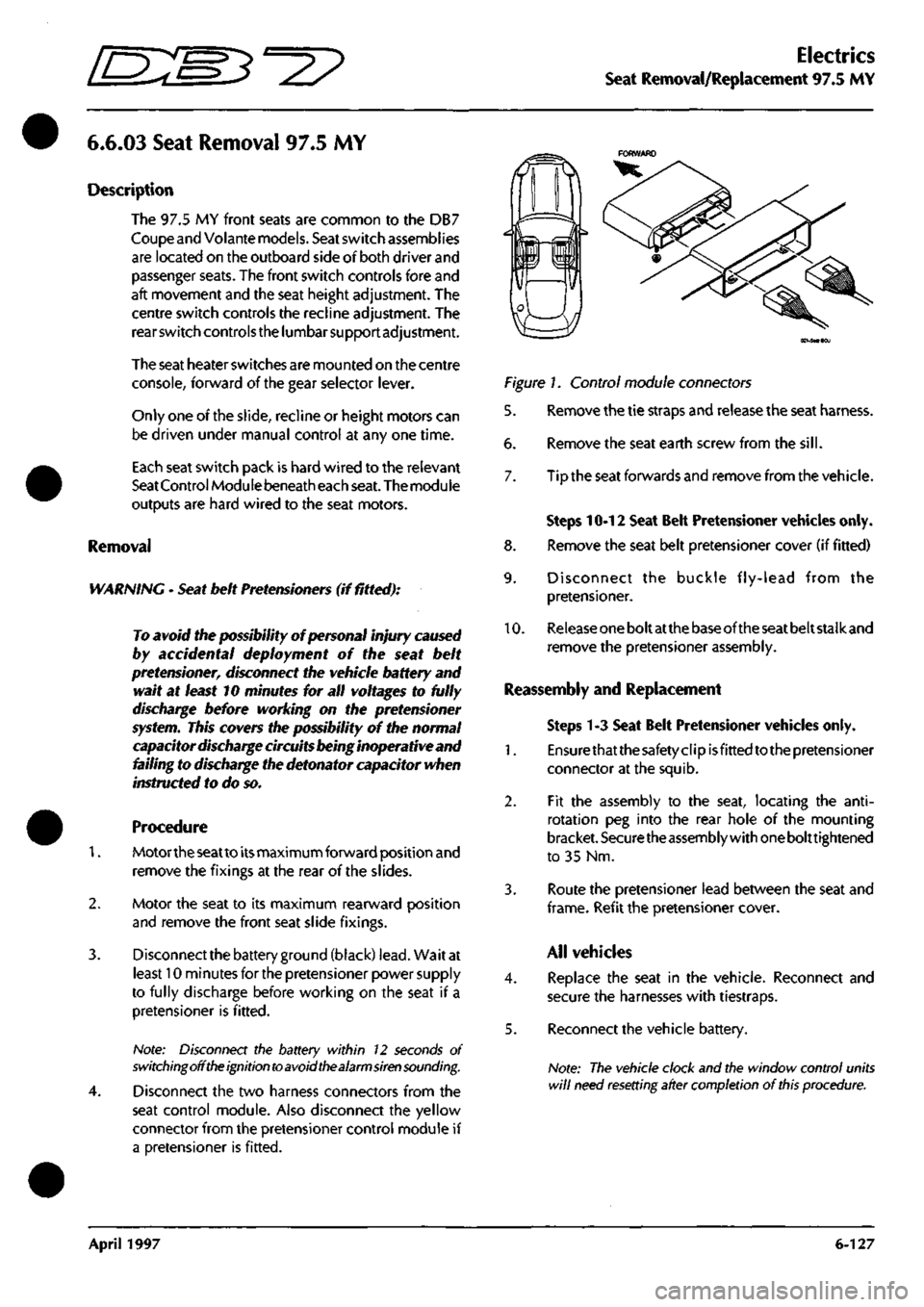
Disconnect the two harness connectors from the
seat control module. Also disconnect the yellow
connector from the pretensioner control module if
a pretensioner is fitted.
Figure 1. Control module connectors
5. Remove the tie straps and release the seat harness.
6. Remove the seat earth screw from the
sill.
7. Tip the seat forwards and remove from the vehicle.
Steps 10-12 Seat Belt Pretensioner vehicles only.
8. Remove the seat belt pretensioner cover (if fitted)
9. Disconnect the buckle fly-lead from the
pretensioner.
10.
Release
one
bolt at
the
base of the
seat
belt stalk and
remove the pretensioner assembly.
Reassembly and Replacement
Steps 1-3 Seat Belt Pretensioner vehicles only.
1.
Ensurethatthesafetyclipisfittedtothepretensioner
connector at the squib.
2.
Fit the assembly to the seat, locating the
anti-
rotation peg into the rear hole of the mounting
bracket.
Securethe
assembly with
one
bolttightened
to 35 Nm.
3. Route the pretensioner lead between the seat and
frame.
Refit the pretensioner
cover.
All vehicles
4.
Replace the seat in the vehicle. Reconnect and
secure the harnesses with tiestraps.
5. Reconnect the vehicle battery.
Note:
The vehicle clock and the window control units
will
need resetting after completion
of
this
procedure.
April 1997 6-127
Page 278 of 421
in:!M3^^?
Air Conditioning
Contents
Contents
General Description 8-5
Specifications 8-5
Climate Control System 8-6
System Description 8-7
Special Servicing Tools and Equipment 8-7
Working Practices 8-8
General 8-8
Handling Refrigerant 8-8
Handling Lubricating Oil 8-8
System Maintenance 8-8
Temperature Distribution System 8-9
Fan Speed Control (Mode Switch) 8-10
Face Level Temperature Differential 8-10
Temperature Rotary Control 8-10
Refrigeration Cycle 8-11
System Protection 8-12
General System Procedures 8-12
Leak Test 8-12
Charge Recovery (System Depressurisation) 8-12
Evacuating the System 8-13
Adding Compressor Lubricating Oil 8-13
Adding Refrigerant 8-14
Functional Check 8-15
System Trouble Shooting 8-1 7
Electronic Control Module (ECM) 8-19
In Car Controls 8-21
Temperature Demand Switch 8-21
Face Level Differential Controller 8-21
Air Conditioning Function Switch 8-22
Fan Speed Control Switch (Mode Switch) 8-23
Temperature Sensors 8-23
Evaporator Sensor 8-24
Motorised In-Car Aspirated Sensor 8-24
Water Temperature Switch 8-25
Blower Motors 8-25
Potentiometers 8-26
Servo Motors 8-27
Vacuum System 8-28
Pressure-Temperature Graphs 8-29
May 1996 8-1
Page 282 of 421
Em^^^?
Air Conditioning
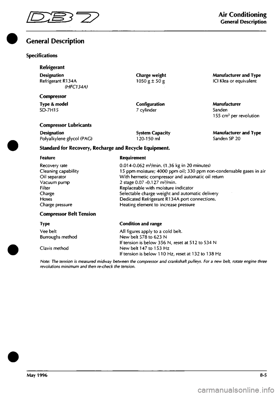
General Description
General Description
Specifications
Refrigerant
Designation
Refrigerant R134A
(HFCUAA)
Compressor
Type
&
model
SD-7H15
Charge weight
1050g±50g
Configuration
7 cylinder
Compressor Lubricants
Designation
Polyalkylene glycol
(PAG)
Standard
for
Recovery, Recharge
and
Recycle Equipment,
System Capacity
120-150
ml
Manufacturer and Type
ICI Klea
or
equivalent
Manufacturer
Sanden
155 cm^
per
revolution
Manufacturer and Type
Sanden SP
20
Feature
Recovery rate
Cleaning capability
Oil separator
Vacuum pump
Filter
Charge
Hoses
Charge pressure
Compressor Belt Tension
Type
Vee belt
Burroughs method
Clavis method
Requirement
0.014-0.062
mVmin.
(1.36 kg in 20
minutes)
15
ppm
moisture; 4000
ppm oil; 330 ppm
non-condensable gases
in air
With hermetic compressor and automatic
oil
return
2 stage
0.07
-0.127 mVmin.
Replaceable with moisture indicator
Selectable charge weight and automatic delivery
Dedicated Refrigerant R134A port connections.
Heating element
to
increase pressure
Condition and range
All figures apply
to a
cold belt.
New belt
578 to 623 N
If tension
is
below
356 N,
reset
at 512 to 534 N
New belt
147 to 153 Hz
If tension
is
below
110 Hz,
reset
at 132 to 138 Hz
Note:
The
tension
is
measured
midway between the
compressor
and crankshaft pulleys. For a new
belt,
rotate engine three
revolutions minimum and then re-check the tension.
May 1996
8-5
Page 287 of 421
Air Conditioning
Temperature Distribution System
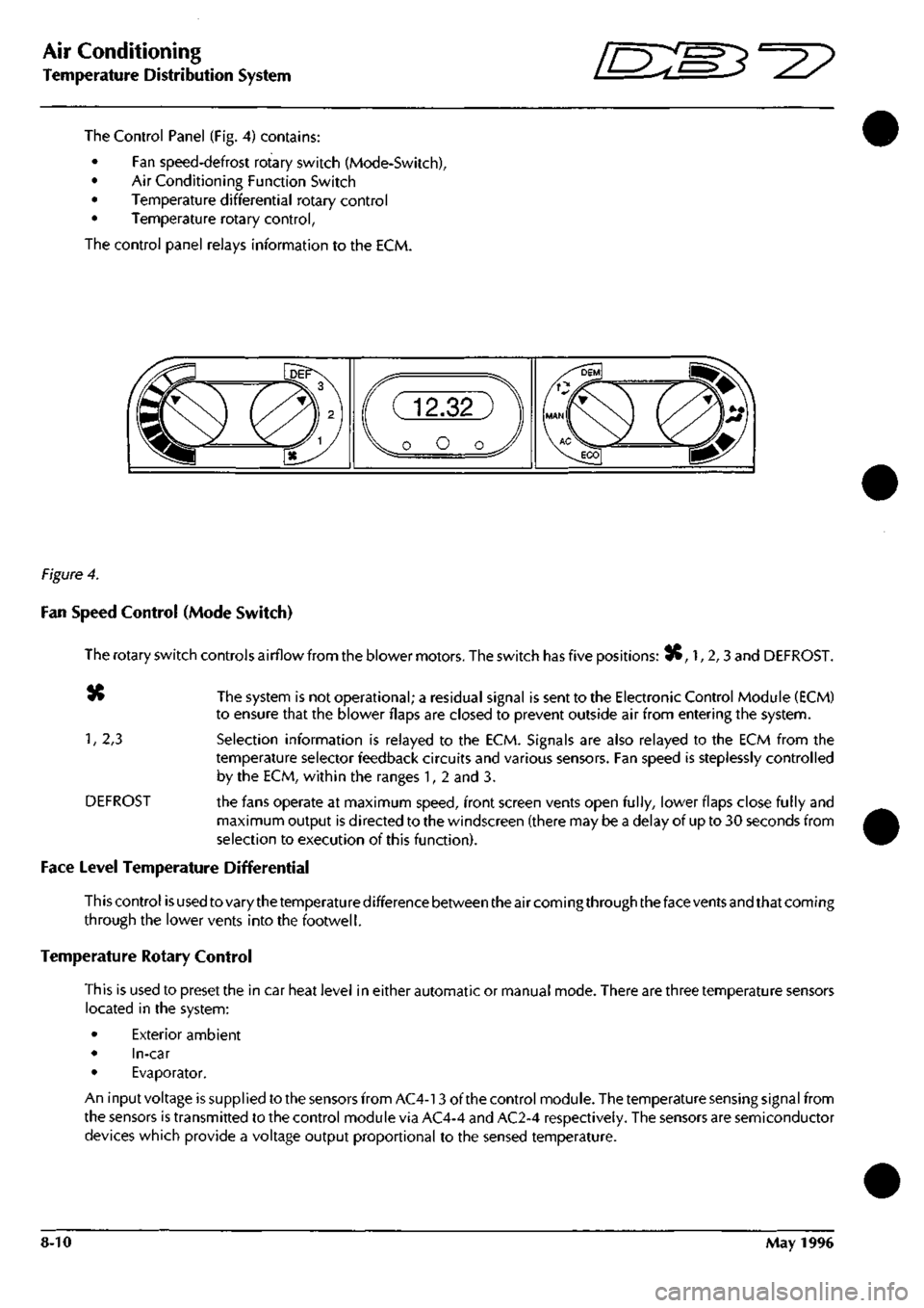
The Control Panel (Fig. 4) contains:
• Fan speed-defrost rotary switch (Mode-Switch),
• Air Conditioning Function Switch
• Temperature differential rotary control
• Temperature rotary control,
The control panel relays information to the ECM.
Figure 4.
Fan Speed Control (Mode Switch)
The rotary switch controls airflow from the blower motors. The switch has five positions: 3C, 1, 2,3 and DEFROST.
«» The system is not operational; a residual signal is sent to the Electronic Control Module (ECM)
to ensure that the blower flaps are closed to prevent outside air from entering the system.
1,
2,3 Selection information is relayed to the ECM. Signals are also relayed to the ECM from the
temperature selector feedback circuits and various sensors. Fan speed is steplessly controlled
by the ECM, within the ranges 1, 2 and 3.
DEFROST the fans operate at maximum speed, front screen vents open fully, lower flaps close fully and
maximum output is directed to the windscreen (there may be a delay of up to 30 seconds from
selection to execution of this function).
Face Level Temperature Differential
This control is used to vary the temperature difference between the air coming through the face vents and that coming
through the lower vents into the footwell.
Temperature Rotary Control
This is used to preset the in car heat level in either automatic or manual mode. There are three temperature sensors
located in the system:
• Exterior ambient
• In-car
• Evaporator.
An input voltage is supplied to the sensors from AC4-13 of the control module. The temperature sensing signal from
the sensors is transmitted to the control module via AC4-4 and AC2-4 respectively. The sensors are semiconductor
devices which provide a voltage output proportional to the sensed temperature.
8-10 May 1996
Page 288 of 421
^7
Air Conditioning
Temperature Distribution System
Air Conditioning Function Switch
When AC, DEM or Re-circulation ^v is selected the system engages the Air conditioning compressor using the
electromagnetic clutch. The in-car temperature is automatically corrected to the pre selected level by the system
sensors.
When MAN (manual mode) is selected it provides the operator selection of fan speed and in-car temperature
selection facilities. The in-car temperature is not thermostatically corrected to a predetermined level by the system
sensors.
When ECO is selected the system is in economy mode which allows the fan speed and heating levels to be selected
but gives no cooling. The air conditioning compressor is not engaged putting a minimum load on the engine.
When manual re-circulation is selected the blower flaps are closed and only that air which is in the vehicle is re
circulated.
When the ignition is turned off the blower flaps revert to the fresh air position.
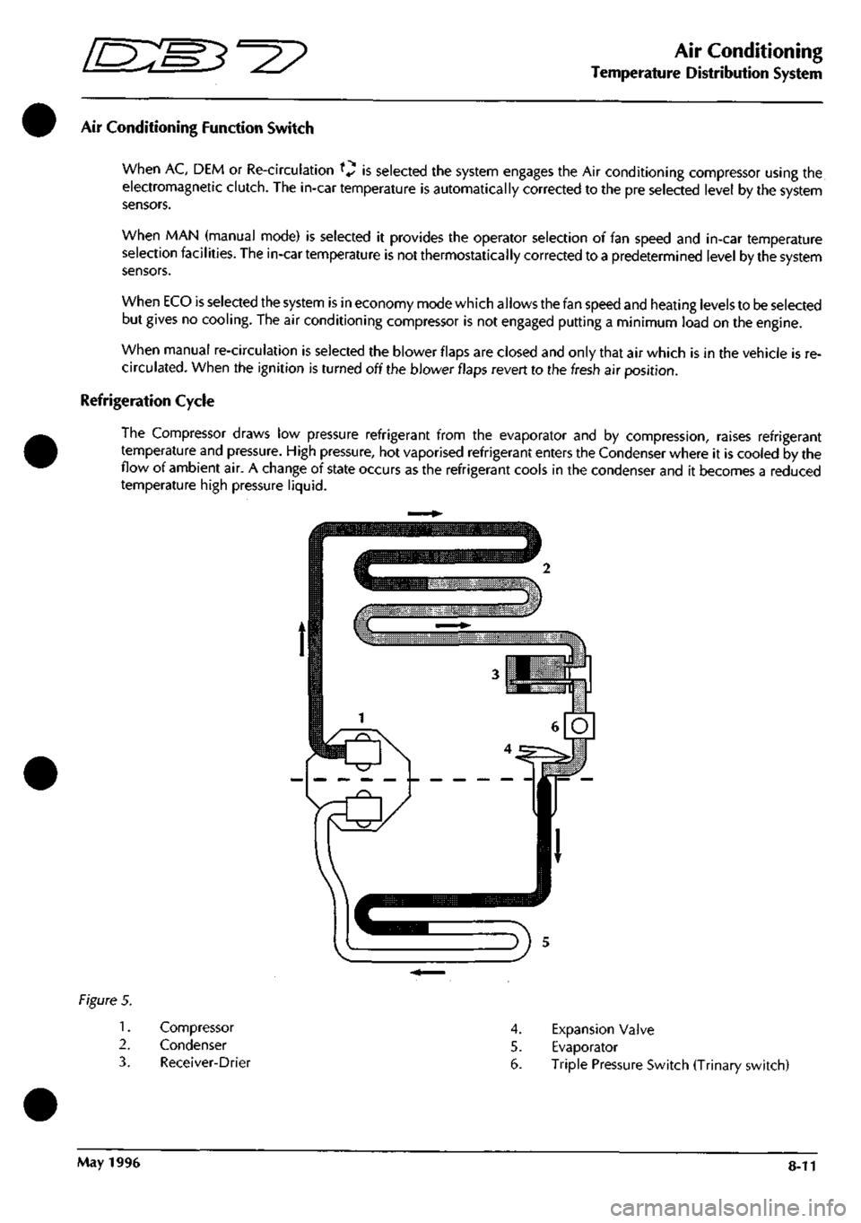
Refrigeration Cycle
The Compressor draws low pressure refrigerant from the evaporator and by compression, raises refrigerant
temperature and pressure. High pressure, hot vaporised refrigerant enters the Condenser where it is cooled by the
flow of ambient air. A change of state occurs as the refrigerant cools in the condenser and it becomes a reduced
temperature high pressure liquid.
Figure 5.
1.
2.
3.
Compressor
Condenser
Receiver-Drier
4.
Expansion Valve
5. Evaporator
6. Triple Pressure Switch (Trinary switch)
May 1996 8-11
Page 299 of 421
Air Conditioning
In Car Controls '^^
Air Conditioning Function Switch
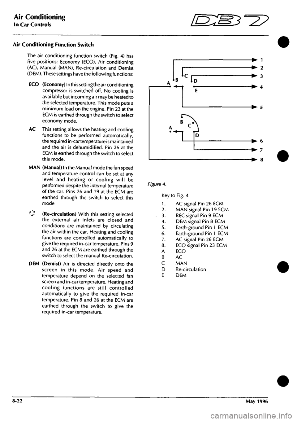
The air conditioning function switch (Fig. 4) has
five positions: Economy (ECO), Air conditioning
(AC),
Manual (MAN), Re-circulation and Demist
(DEM). These settings have thefol lowing functions:
ECO (Economy) Inthissettingtheairconditioning
compressor is switched off. No cooling is
available but incoming air may be heated to
the selected temperature. This mode puts a
minimum load on the engine. Pin 23 at the
ECM is earthed through the switch to select
economy mode.
AC This setting allows the heating and cooling
functions to be performed automatically,
the required in-cartemperature
is
maintained
and the air is dehumidified. Pin 26 at the
ECM is earthed through the switch to select
this mode.
MAN (Manual) In the Manual mode the fan speed
and temperature control can be set at any
level and heating or cooling will be
performed despite the internal temperature
of the car. Pins 26 and 19 at the ECM are
earthed through the switch to select this
mode
V (Re-circulation) With this setting selected
the external air inlets are closed and
conditions are maintained by circulating
the air within the car. Heating and cooling
functions are controlled automatically to
give the required in-cartemperature. Pins 9
and 26 at the ECM are earthed through the
switch to select the manual Re-circulation.
DEM (Demist) Air is directed directly onto the
screen in this mode. Air speed and
temperature depend on the selected fan
screen and in-cartemperature. Heating and
cooling functions are still controlled
automatically to give the required in-car
temperature. Pin 8 and 26 at the ECM are
earthed through the switch to give the
required in-car temperature.
B
liD^
-• 1
-• 2
-• 3
-• 4
-• 5
,'^
1 -• 6
-• 7
-• 8
Figure 4.
Key to Fig. 4
1.
AC signal Pin 26 ECM
2.
MAN signal Pin 19 ECM
3. REC signal Pin 9 ECM
4.
DEM signal Pin 8 ECM
5. Earth-ground Pin 1 ECM
6. Earth-ground Pin 1 ECM
7. AC signal Pin 26 ECM
8. ECO signal Pin 23 ECM
A ECO
B AC
C MAN
D Re-circulation
E DEM
8-22 May 1996
Page 307 of 421
Air Conditioning
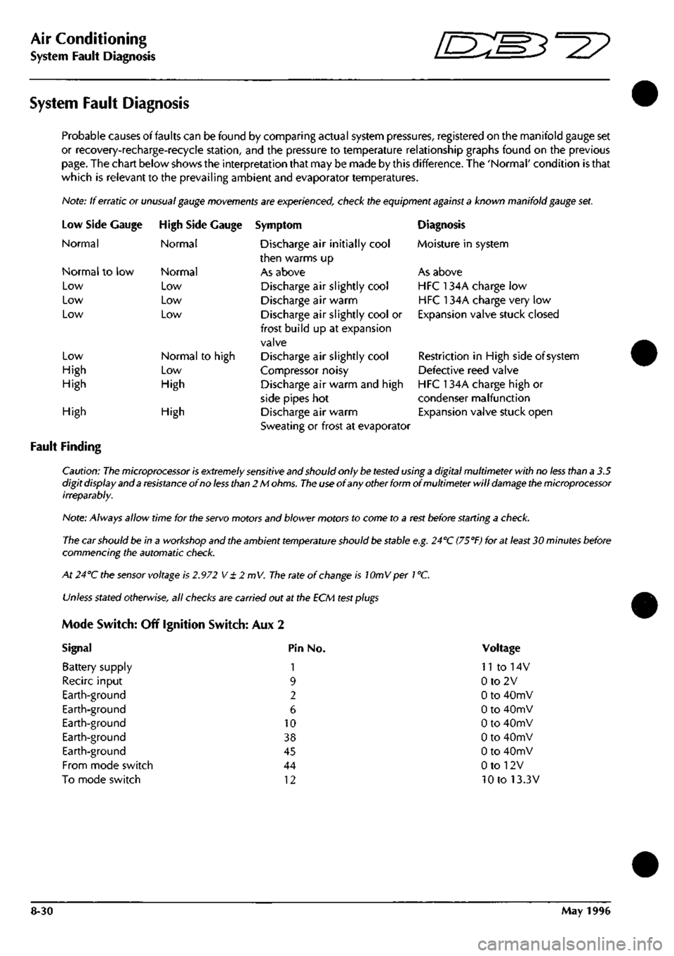
System Fault Diagnosis ^=2?
System Fault Diagnosis
Probable causes of faults can be found by comparing actual system pressures, registered on the manifold gauge set
or recovery-recharge-recycie station, and the pressure to temperature relationship graphs found on the previous
page.
The chart below shows the interpretation that may be made by this difference. The 'Normal' condition is that
which is relevant to the prevailing ambient and evaporator temperatures.
Note: If erratic or
unusual gauge movements
are experienced, check the equipment
against a
known manifold
gauge
set.
Low Side
Normal
Gauge
Normal to low
Low
Low
Low
Low
High
High
High Side Gauge
Normal
Normal
Low
Low
Low
Normal to high
Low
High
High
Fault Finding
High
Symptom
Discharge air initially cool
then warms up
As above
Discharge air slightly cool
Discharge air warm
Discharge air slightly cool or
frost build up at expansion
valve
Discharge air slightly cool
Compressor noisy
Discharge air warm and high
side pipes hot
Discharge air warm
Sweating or frost at evaporator
Diagnosis
Moisture in system
As above
HFC 134A charge low
HFC 134A charge very low
Expansion valve stuck closed
Restriction in High side of system
Defective reed valve
HFC 134A charge high or
condenser malfunction
Expansion valve stuck open
Caution:
The microprocessor is extremely sensitive
and should only
be tested
using
a
digital multimeter with no
less
than a 3.5
digit display and a
resistance
of no
less than
2 M
ohms.
The use
of any other form of multimeter will
damage the microprocessor
irreparably.
Note: Always allow time for the
servo
motors and blower motors to come to a
rest
before starting a
check.
The car should be in a workshop and the ambient
temperature
should
be
stable
e.g.
24''C
(75°F)
for at
least
30 minutes before
commencing the automatic
check.
At 24°C the
sensor
voltage is
2.972
V
± 2 mV.
The
rate of
change
is lOmVper
1
°C.
Unless
stated
otherwise,
all
checks
are carried out at the ECM
test plugs
Mode Switch: Off Ignition Switch: Aux 2
Signal Pin No.
Battery supply 1
Recirc input 9
Earth-ground 2
Earth-ground 6
Earth-ground 10
Earth-ground 38
Earth-ground 45
From mode switch 44
To mode switch 12
Voltage
n to 14v
0to2V
0 to 40mV
0 to 40mV
0 to 40mV
0 to 40mV
0 to 40mV
0 to 12V
10 to 13.3V
8-30 May 1996
Page 325 of 421
Air Conditioning
Refrigerant Recovery and Recycling ^=2?
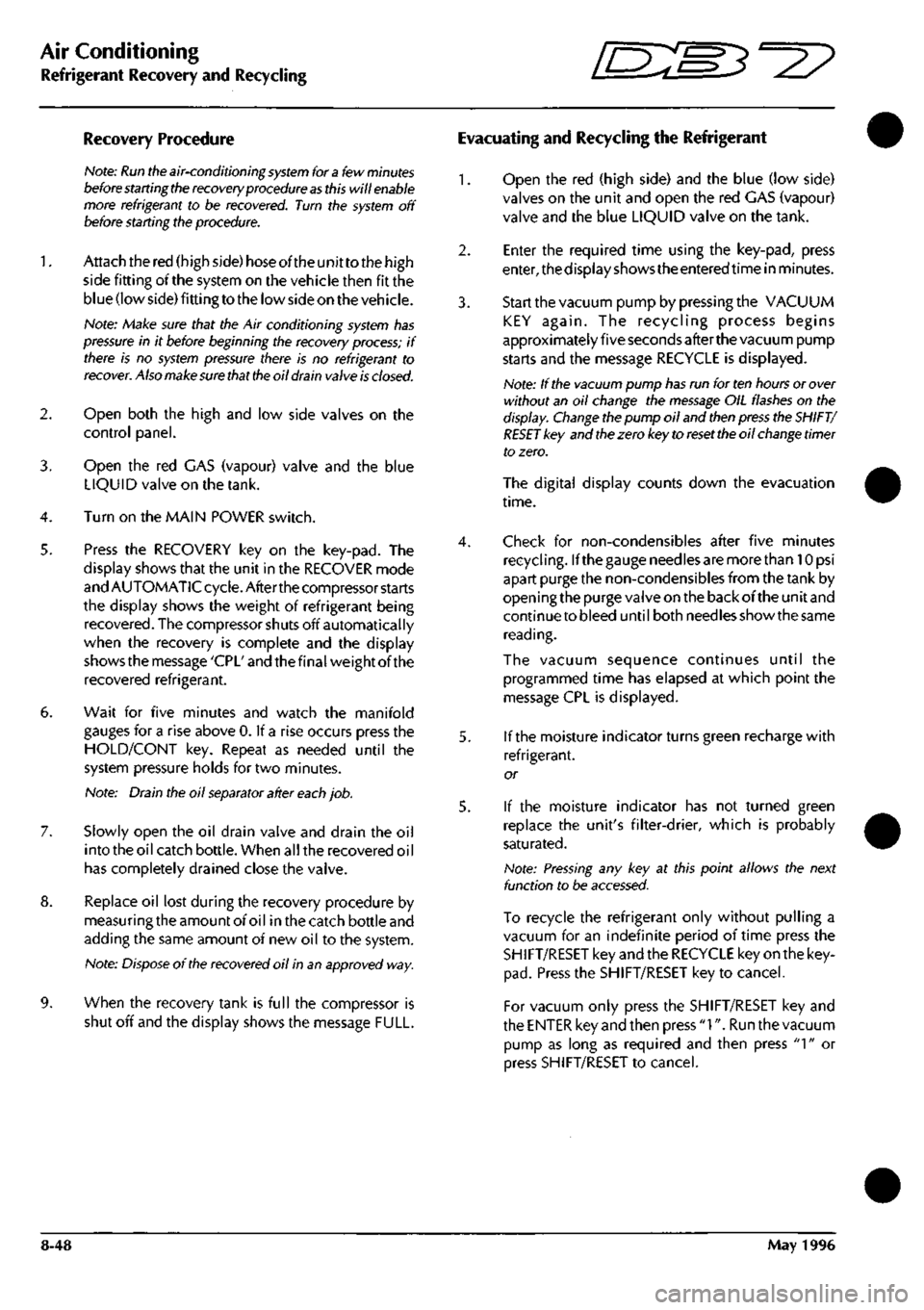
Recovery Procedure
Hote:
Run the
air-conditioning
system
for
a
few
minutes
before starting the
recovery
procedure as
this will
enable
more refrigerant to be recovered. Turn the
system
off
before
starting
the procedure.
1.
Attach the red (high side) hose oftheunittothe high
side fitting of the system on the vehicle then fit the
blue (low side) fitting to the low side on the vehicle.
Note: Make sure that the Air conditioning
system
has
pressure in it before beginning the recovery
process;
if
there is no
system
pressure there is no refrigerant to
recover.
Also
make sure that the
oil
drain
valve
is
closed.
2. Open both the high and low side valves on the
control panel.
3. Open the red CAS (vapour) valve and the blue
LIQUID valve on the tank.
4.
Turn on the MAIN POWER switch.
5. Press the RECOVERY key on the key-pad. The
display shows that the unit in the RECOVER mode
and AUTOMATIC cycle. After the compressor starts
the display shows the weight of refrigerant being
recovered.
The compressor shuts off automatically
when the recovery is complete and the display
shows the message 'CPL' and the final weight of the
recovered refrigerant.
6. Wait for five minutes and watch the manifold
gauges for a rise above 0. If a rise occurs press the
HOLD/CONT key. Repeat as needed until the
system pressure holds for two minutes.
Note: Drain the oil
separator
after
each
job.
7. Slowly open the oil drain valve and drain the oil
into the oil catch bottle. When all the recovered oil
has completely drained close the valve.
8. Replace oil lost during the recovery procedure by
measuringthe amount of oil inthe catch bottle and
adding the same amount of new oil to the system.
Note:
Dispose
of the
recovered
oil in an approved way.
9. When the recovery tank is full the compressor is
shut off and the display shows the message FULL.
Evacuating and Recycling the Refrigerant
1.
Open the red (high side) and the blue (low side)
valves on the unit and open the red GAS (vapour)
valve and the blue LIQUID valve on the tank.
2.
Enter the required time using the key-pad, press
enter,thedisplayshowstheenteredtime in minutes.
3. Start the vacuum pump by pressing the VACUUM
KEY again. The recycling process begins
approximately five seconds after the vacuum pump
starts and the message RECYCLE is displayed.
Note: If the vacuum pump
has
run for ten hours or
over
without an oil change the
message
OIL
flashes
on the
display.
Change
the pump oil and
then press
the
SHIFT/
RESET key and
the
zero key to
reset the
oil
change
timer
to zero.
The digital display counts down the evacuation
time.
4.
Check for non-condensibles after five minutes
recycling.
Ifthegauge needles are more than lOpsi
apart purge the non-condensibles from the tank by
open
i ng
the purge valve on the back of the
un
it and
continue to bleed until both needles show the same
reading.
The vacuum sequence continues until the
programmed time has elapsed at which point the
message CPL is displayed.
5. If the moisture indicator turns green recharge with
refrigerant.
or
5. If the moisture indicator has not turned green
replace the unit's filter-drier, which is probably
saturated.
Note:
Pressing
any key at this point allows the next
function to be
accessed.
To recycle the refrigerant only without pulling a
vacuum for an indefinite period of time press the
SHIFT/RESET key and the RECYCLE key on the key
pad.
Press the SHIFT/RESET key to cancel.
For vacuum only press the SHIFT/RESET key and
the ENTER key and then press
"1".
Run the vacuum
pump as long as required and then press
"1"
or
press SHIFT/RESET to cancel.
8-48 May 1996