AUX ASTON MARTIN DB7 1997 Workshop Manual
[x] Cancel search | Manufacturer: ASTON MARTIN, Model Year: 1997, Model line: DB7, Model: ASTON MARTIN DB7 1997Pages: 421, PDF Size: 9.31 MB
Page 29 of 421
[n:m3^y
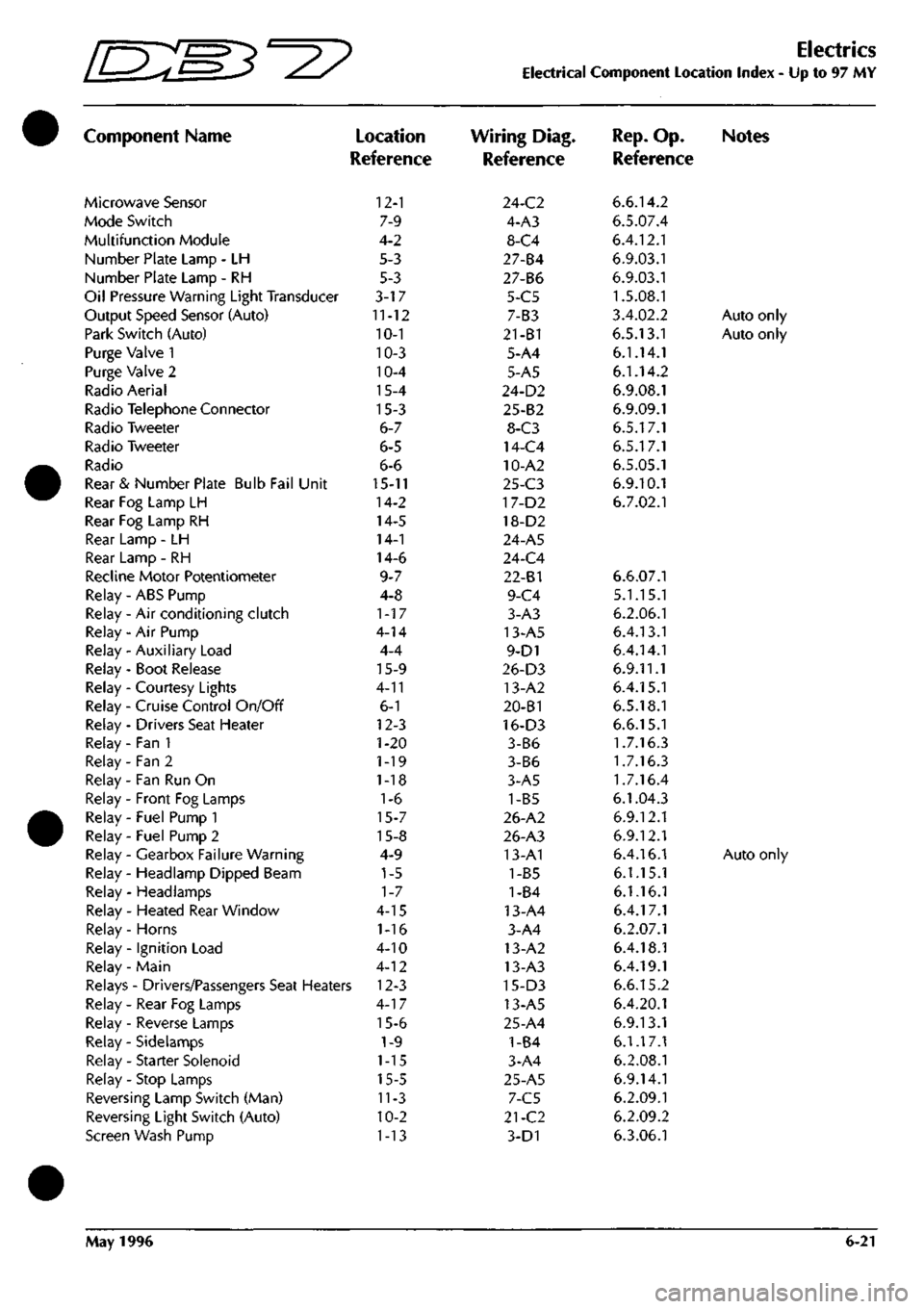
Component Name
Microwave Sensor
Mode Switch
Multifunction Module
Number Plate Lamp - LH
Number Plate Lamp - RH
Oil Pressure Warning Light Transducer
Output Speed Sensor (Auto)
Park Switch (Auto)
Purge Valve 1
Purge Valve 2
Radio Aerial
Radio Telephone Connector
Radio Tweeter
Radio Tweeter
Radio
Rear & Number Plate Bulb Fail Unit
Rear Fog Lamp LH
Rear Fog Lamp RH
Rear Lamp - LH
Rear Lamp - RH
Recline Motor Potentiometer
Relay - ABS Pump
Relay - Air conditioning clutch
Relay - Air Pump
Relay - Auxiliary Load
Relay - Boot Release
Relay - Courtesy Lights
Relay - Cruise Control On/Off
Relay - Drivers Seat Heater
Relay - Fan 1
Relay - Fan 2
Relay - Fan Run On
Relay - Front Fog Lamps
Relay - Fuel Pump 1
Relay - Fuel Pump 2
Relay - Gearbox Failure Warning
Relay - Headlamp Dipped Beam
Relay - Headlamps
Relay - Heated Rear Window
Relay - Horns
Relay - Ignition Load
Relay - Main
)
Location
Reference
12-1
7-9
4-2
5-3
5-3
3-17
11-12
10-1
10-3
10-4
15-4
15-3
6-7
6-5
6-6
15-11
14-2
14-5
14-1
14-6
9-7
4-8
1-17
4-14
4-4
15-9
4-11
6-1
12-3
1-20
1-19
1-18
1-6
15-7
15-8
4-9
1-5
1-7
4-15
1-16
4-10
4-12
Relays - Drivers/Passengers Seat Heaters 12-3
Relay - Rear Fog Lamps
Relay - Reverse Lamps
Relay - Sidelamps
Relay - Starter Solenoid
Relay - Stop Lamps
Reversing Lamp Switch (Man)
Reversing Light Switch (Auto)
Screen Wash Pump
4-17
15-6
1-9
1-15
15-5
11-3
10-2
1-13
Electrics
Electrical Component Location Index - Up to 97 MY
Wiring Diag.
Reference
24-C2
4-A3
8-C4
27-84
27-B6
5-C5
7-B3
21-B1
5-A4
5-A5
24-D2
25-B2
8-C3
14-C4
10-A2
25-C3
17-D2
18-D2
24-A5
24-C4
22-81
9-C4
3-A3
13-A5
9-D1
26-D3
13-A2
20-B1
16-D3
3-B6
3-B6
3-A5
1-B5
26-A2
26-A3
13-A1
1-B5
1-84
13-A4
3-A4
13-A2
13-A3
15-D3
13-A5
25-A4
1-B4
3-A4
25-A5
7-C5
21-C2
3-D1
Rep.
Op. Notes
Reference
6.6.14.2
6.5.07.4
6.4.12.1
6.9.03.1
6.9.03.1
1.5.08.1
3.4.02.2
Auto only
6.5.13.1
Auto only
6.1.14.1
6.1.14.2
6.9.08.1
6.9.09.1
6.5.17.1
6.5.17.1
6.5.05.1
6.9.10.1
6.7.02.1
6.6.07.1
5.1.15.1
6.2.06.1
6.4.13.1
6.4.14.1
6.9.11.1
6.4.15.1
6.5.18.1
6.6.15.1
1.7.16.3
1.7.16.3
1.7.16.4
6.1.04.3
6.9.12.1
6.9.12.1
6.4.16.1
Auto only
6.1.15.1
6.1.16.1
6.4.17.1
6.2.07.1
6.4.18.1
6.4.19.1
6.6.15.2
6.4.20.1
6.9.13.1
6.1.17.1
6.2.08.1
6.9.14.1
6.2.09.1
6.2.09.2
6.3.06.1
May 1996 6-21
Page 67 of 421
NO COLOUR 4
NP
5
VS
14
WU
17
GW
51
RO
61
BR
65
UB
70
yw
71
YB
77
RS
79
RG
83
WK
66
BK
87
YR
90
OR
91
W
92
NR
95
R
94
RY
95
U
96
UW
97
OY
98
YP
99
YO
121
m
156 UB 138 RN 198 GN 207
NB
209
OK
222 OS 226 BH 248
NS
249
LGO
250
WS
252
WY
253
UG
255
G
258
KB
259
OR
260
0
261
NR
262 BLG 263
WR
520
P
321 PW 322 RU 323
GU
324
Y
325
LG
328
RN
330 YC 331
YU
336 W 340 B 346 NW 347 NY 351 V«U 352
W
354
W
355
WR
AREA 03 A6 A6 A6 A6 B5-88 A6 A6 B6 C2-7I C2-7I B6 B6 B4-84 86 B4-66 86 B5-87 86 B6 86 86 86 B6 B6 B6 B6 86 B6 86 86 86 B6 83-77 C6 C6 C6 C6 C6 C6 C6 C6 C6 02 83-75 C6 C6 C6 C6 C6 C6 C6 C6 B4-86 A3 02 B3-76 C6 B4-ee C6 CG
NO COLOUB 356
WLG
357 8LC 558
BR
559 0
561 NK 362 RW 363 P 364 NG 366 WK 367 OW 366 OS 369 OU 372
BR
374
WR
575
NR
377
BG
578
BS
379
BY
380 PG 581 BP 582
WB
585 K 584
WP
385 8U 386 CO 387 BW 388 PS 405 NU 407 B 411
B
419 NB 430 P 447 KB 471 BW 472
B
473
B
510
B
536 8 551
B
552
B
565
B
604 NB 618
8
622
KB
699 NU 715
BK
717
OU
718 OW
AREA A2 A2 A2 82-72
C2 C6 B3-75 C4 03-80 02 C6 C6 85-88 64-86 06 06 06 06 06 06 06 06 06 06 A6 A6 A6 C5 01 01 A2 02 04 86 B6 86 C6 C6 C6 C6 C6 C6 C6 C6 06 B4-85 D6 06
NO COLOUn 596 BK 397 W 398 N 399 NY
PIN 85 86 87 }0
AREA B4-85 84-86 A2
6?-m
AUX LOAD RELAY
^5^
HEATED FRONT SCREEN CONTROLER
N6
toLwk
l>lli
IRET
400 N
I B4
jiaaii
2__s!
HEATED FRONT SCREEN FOSE
40A
I
HI>
cALbUR AREA
I "PI if «t
WIPER LOGIC MODULE NO CdLOUt 340 B 415
0
416 LGG 417 LGW 418 LGN 357 BLG 356 WLG 358 BR 109 LGB
419 NB 420 LGP 421
LG
422
LGR
t2?B5
PIN 1 2 3 4 5 6 7 8 9 10 II 12 15 14 IS
'i
AREA
a
B2-72 B6 86 B6 Al Al Al 86
81 B6 86 86 86
-«•
SHEET
8
AREA
6
NO COLOUF 407 B 408 WK 409 WO
410
N
l>IH 85 86 87 87A
W
AREA Bl C5-80 B2-74
B?-'?
AUX LOAD RELAY
t_jRH
Fl
IFAIL
I
I I I
SPL
72
SPL
75
SPL
74 SPL 75
wmmrmr^m'
424
WP
U
C3-ei
SUM W H
1
H FRONT BULB FAIL MODULE
NO COLOUR 402 WS 405 R 404 RG
PIN AREA 86 85-87 «-7l
NO COLOUR AREA 405
NU
Bl
406 N
B4
SPL
86
SPL
88
I
I I I
NO COLOUR 400 N 406 N 428
N
444 N 465 N 465 N 466 N 467 N
AREA A2 C2 D2 02 04 84-83 B3-78 B3-79
SHEET
10
AREA
I
5>
6»
NO COLOUR 468 WP 469 WK 470 NU 464 NO
PIN 85 86 87
??
AREA C3-8I C3-80 B6 04
WINDOW LIFT THERMAL BREAKER
NO COLOUR 411
B
412 WK 413 WK
414
N
PIN 85 86 87 87A
59
AREA 81 C3-80 82-75
n.-.n
NO COLOUR
PIN
428 N 361 NK 429
N
450 P 451 N 346 NW 452 N 435 P 434 WO 435 WU 436 WK 437 LG 438 W 263
WR
439 W
4400
441
WO
367
OW
442 W 172 G 444 N ilLNL.
I 2 3 4 5 6 7 8 9 10 II 12 13 14 15 16 17 18 19 20 21 -22-
TRpr
B4 Al B3-79 81 83-82 CI B3-78 86 82-74 86 82-73 86 B6
CI
B6
82-72 B2-74 Al
B4-86
Be C4 .M-
M
3! n>
<^
3 oj
Ol
2 W
:*^
"^
— n>
"w
mm I^IN
446 N 464 NG 447 KB 174
KB
448 W 449WK 450 WK 451 LG 452
WX
453 GP 454
N
455 NP 456 N 457 NP 458 W 459 G 460 N 461
P
462 N 4
NP
463 N 464 NO
23 24 25 26 27 28 29 30 31 32 33 34 35 36 37 38 39 40 41 42 45 44
ARTT
B4-83 C6 81 86 B4-86 86 82-73 86 82-73 86 B3-82 86 83-79 B6 84-86 86 83-82 86 83-82 Al C4 C4
COLOUR YS WU GW RO
65
UB 70
YW
71
YB
83
WK
86
BK
90
GR
92
NR
94
RY
95
U
96
UW
97
GY
98
YP
99
YO
109 LGB 121
WR
131
YR
136 UB 138 RN 163 BK 172
G
174
KB
198 GN 207
NB
209
OK
222 OS 226 BN 248
NS
250
WS
252
WY
253
UG
255
G
258
KB
259
OR
260 0 261 NR 262 BLG 321
PW
322 RU
323
GU 324 Y
325
LG
328
RN
330 YG 331
YU
351 WU 354
W
355
WR
AREA 81 81 81 81 Bl 81 81 81 81 Bl 81 81 81 81 81 81 81 AS
CI
B4-84 CI CI C4-85 D3 04 CI CI CI CI
CI
CI CI CI CI CI CI CI CI CI CI CI CI CI CI Bl 81 81 81 Bl 81 Bl
362
RW
368 OS 369 OU 375
BY
377
BG
378 8S 379 BY 380 PG 381 BP 362
WB
383 K 384 WP
Bl CI CI CI CI CI CI Bl Bl 81 Bl 81
NO COLOUR 385 BU 586 00 587
GW
388 PS 401 BY 402 WS
416
LGG 417
LGN
418
LGN
420 LGR 421
LG
422
LOP
423
BS
425
WP
433 P 435 WU 437 LG 438 W 439 W 445 NG 449 WK 451 LG 455 GP 455 NP 457 NP 459 6 461
P
470 NU 471 BW 472
B
473 B 494 BR 498 P 505 LGO 510
B
522
YR
528
BK 536 6 537
W
551
8
552
B
555
W
565 B
566 NY 586 LGO 604 NB 608 0 616
P
618 B 622
KB
649 P 662 N 665 P 668 WO 687 NY 695 P 699 NU 710 R 712 W 714 WK
717
OU
718
OW
JD
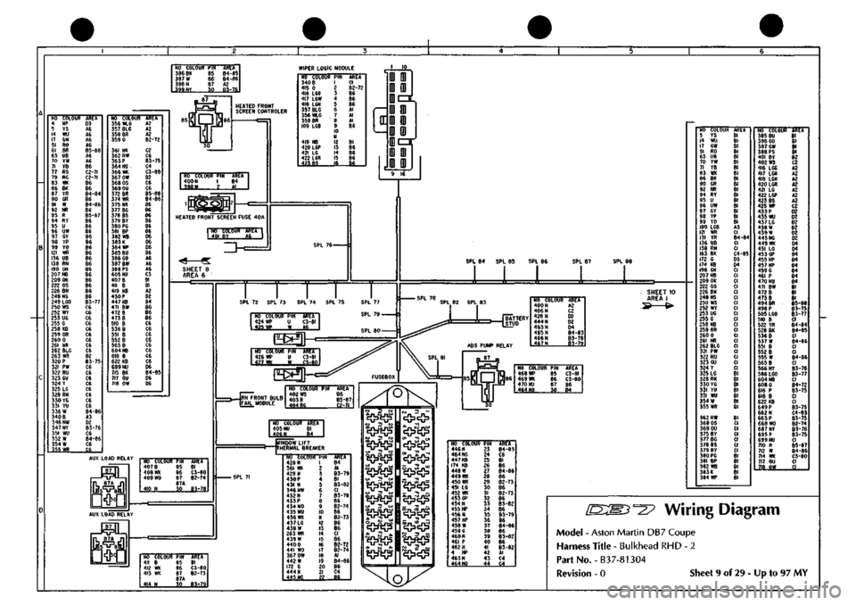
Wiring Diagram
Model
-
Aston Martin DB7 Coupe
Harness Title
-
Bulkhead RHD
- 2
Part No.-B37-81304
TRfT
Bl 81 82 C2 A2 A2 A2 A2 A2 A2 A2 C2 02 D2 02 D2 02 02 04 D4 04 D4 04 04 04 04
Bl Bl Bl
B5-88
85-75
85-77 CI B4-84 84-85 CI 84-86 CI CI
84-86
CI
85-76
B3-77
CI B4-72
83-75
CI CI B3-75 C4-83
B3-75
82-74
83-76
83-75
CI
B5-87
84-86
C3-80 CI .il
Revision -
0
Sheet
9
of 29
-
Up to 97 MY
Page 110 of 421
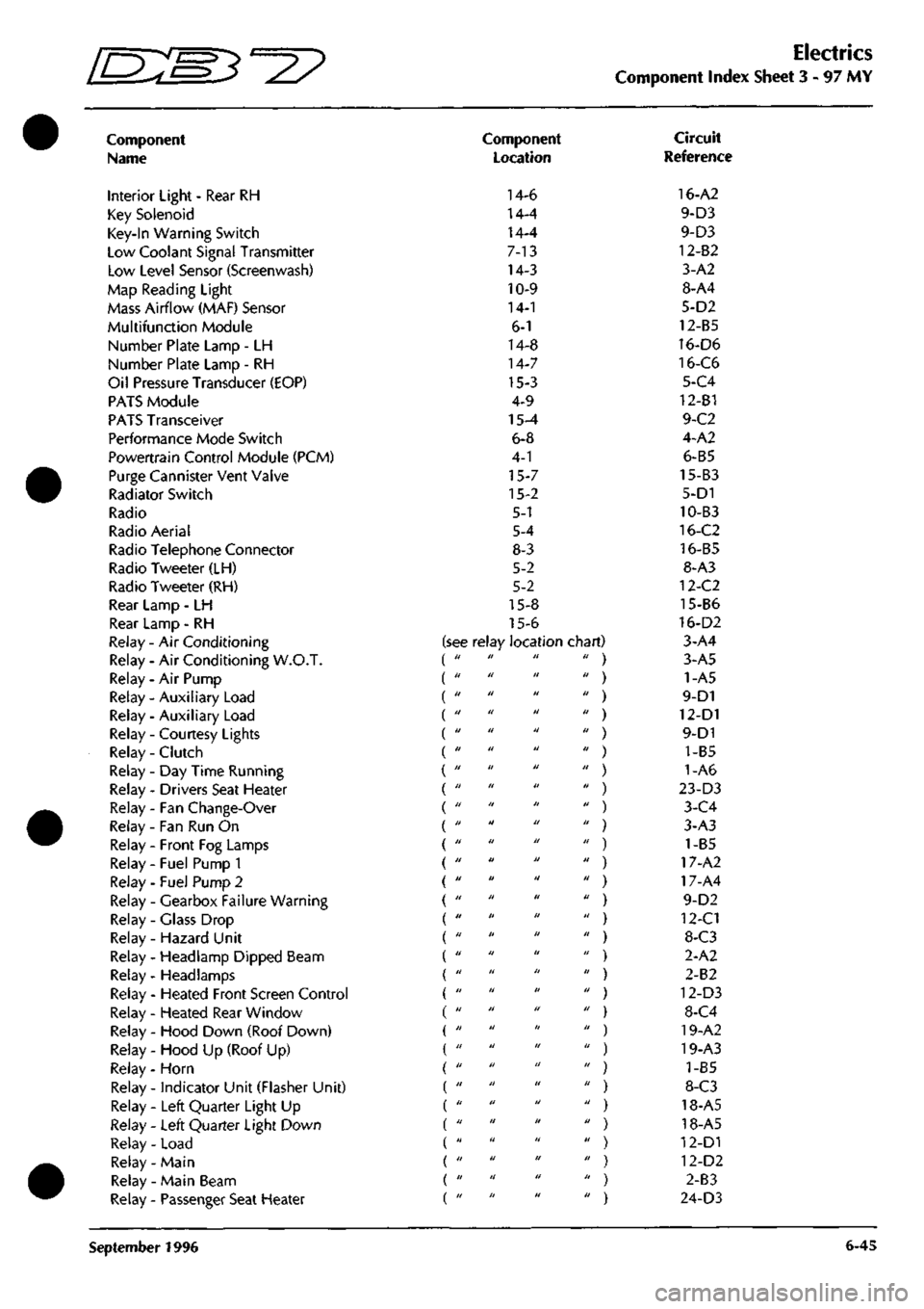
Electrics
Component Index Sheet 3 - 97
MY
Component
Name
Interior Light - Rear RH
Key Solenoid
Key-In Warning Switch
Low Coolant Signal Transmitter
Low Level Sensor (Screenwash)
Map Reading Light
Mass Airflow (MAF) Sensor
Multifunction Module
Number Plate Lamp - LH
Number Plate Lamp - RH
Oil Pressure Transducer (EOP)
PATS Module
PATS Transceiver
Performance Mode Switch
Powertrain Control Module (PCM)
Purge Cannister Vent Valve
Radiator Switch
Radio
Radio Aerial
Radio Telephone Connector
Radio Tweeter (LH)
Radio Tweeter (RH)
Rear Lamp - LH
Rear Lamp - RH
Relay - Air Conditioning
Relay - Air Conditioning W.O.T.
Relay - Air Pump
Relay - Auxiliary Load (
Relay - Auxiliary Load (
Relay - Courtesy Lights (
Relay - Clutch (
Relay-Day Time Running (
Relay - Drivers Seat Heater (
Relay - Fan Change-Over (
Relay - Fan Run On
Relay - Front Fog Lamps
Relay - Fuel Pump 1
Relay - Fuel Pump 2
Relay - Gearbox Failure Warning
Relay - Glass Drop
Relay - Hazard Unit
Relay - Headlamp Dipped Beam
Relay- Headlamps
Relay - Heated Front Screen Control
Relay - Heated Rear Window
Relay - Hood Down (Roof Down)
Relay - Hood Up (Roof Up)
Relay - Horn
Relay - indicator Unit (Flasher Unit)
Relay - Left Quarter Light Up
Relay - Left Quarter Light Down
Relay - Load
Relay- Main
Relay - Main Beam
Relay - Passenger Seat Heater
Component
Location
14-6
14-4
14-4
7-13
14-3
10-9
14-1
6-1
14-8
14-7
15-3
4-9
15-4
6-8
4-1
15-7
15-2
5-1
5-4
8-3
5-2
5-2
15-8
15-6
see relay location chart) di II II II
II II II II
II II II II
11 II II II
II II II II
II II II II
II II II II
II II II II
II II II II
11 II II II
II II II II
II II II II
II II It II
II II II II
11 II II II
II II II II
II II II II
II II II II
II II II II
II It II II
II II II II
11 II II II
II II II II
11 II II II
11 II II II
II II II II
II II II II
II II II II
II II II II
II II II II
Circuit
Reference
16-A2
9-D3
9-D3
12-82
3-A2
8-A4
5-D2
12-B5
16-D6
16-C6
5-C4
12-B1
9-C2
4-A2
6-B5
15-B3
5-D1
10-B3
16-C2
16-B5
8-A3
12-C2
15-B6
16-D2
3-A4
3-A5
1-A5
9-D1
12-D1
9-D1
1-B5
1-A6
23-D3
3-C4
3-A3
) 1-B5
) 17-A2
) 17-A4
9-D2
) 12-C1
) 8-C3
2-A2
) 2-B2
) 12-D3
) 8-C4
) 19-A2
) 19-A3
) 1-85
) 8-C3
) 18-A5
) 18-A5
) 12-D1
) 12-D2
) 2-83
) 24-D3
September 1996 6-45
Page 129 of 421
Electrics
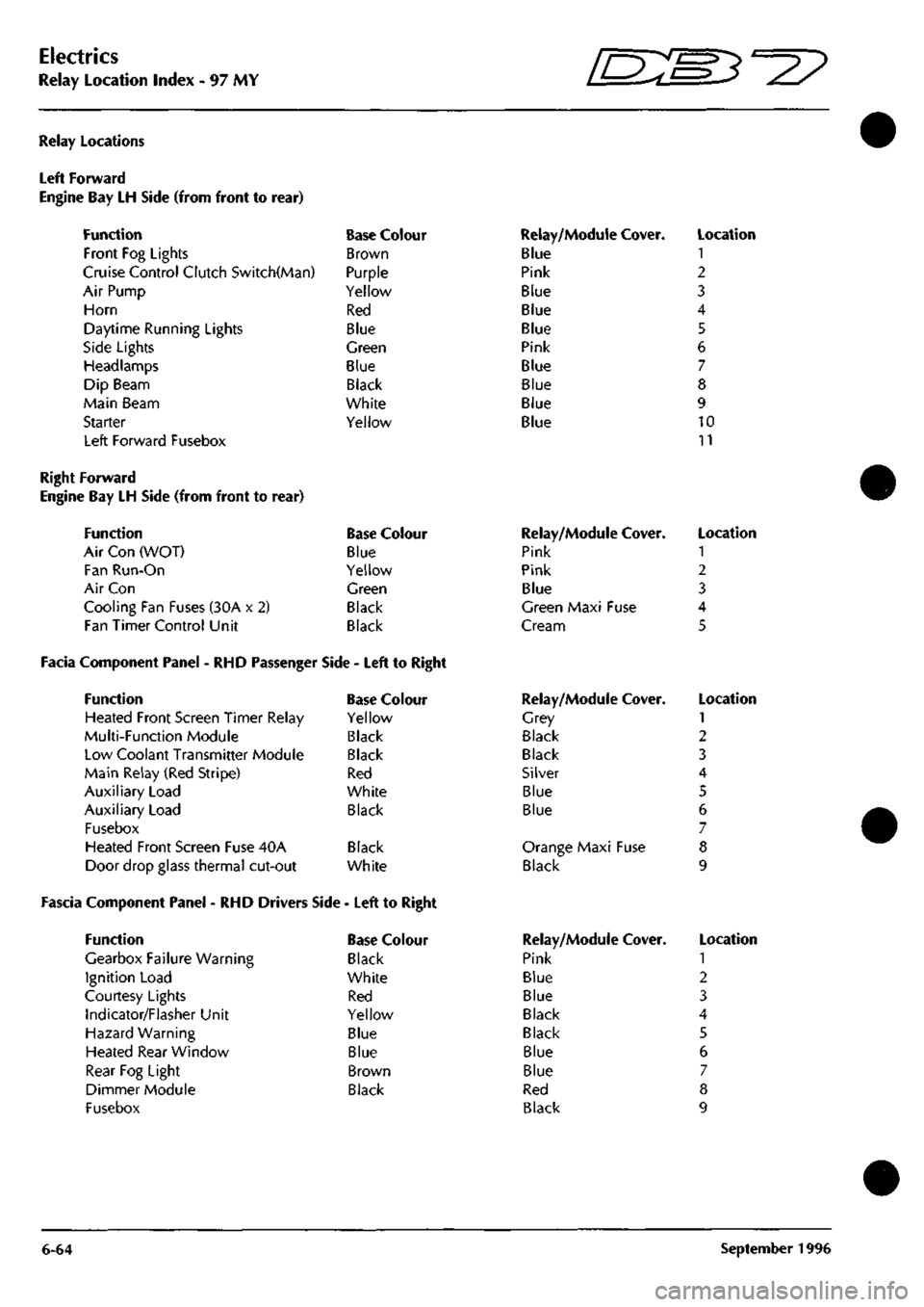
Relay Location Index - 97 MY 5^^?
Relay Locations
Left Forward
Engine Bay LH Side (from front to
Function
Front Fog Lights
rear)
Cruise Control Clutch Switch(Man)
Air Pump
Horn
Daytime Running Lights
Side Lights
Headlamps
Dip Beam
Main Beam
Starter
Left Forward Fusebox
Base Colour
Brown
Purple
Yellow
Red
Blue
Green
Blue
Black
White
Yellow
Relay/Module Cover.
Blue
Pink
Blue
Blue
Blue
Pink
Blue
Blue
Blue
Blue
Location
1
2
3
4
5
6
7
8
9
10
11
Right Forward
Engine Bay LH Side (from front to rear)
Function Base Colour
Air Con (WOT) Blue
Fan Run-On Yellow
Air Con Green
Cooling Fan Fuses (30A x 2) Black
Fan Timer Control Unit Black
Facia Component Panel - RHD Passenger Side - Left to Right
Function Base Colour
Heated Front Screen Timer Relay Yellow
Multi-Function Module Black
Low Coolant Transmitter Module Black
Main Relay (Red Stripe) Red
Auxiliary Load White
Auxiliary Load Black
Fusebox
Heated Front Screen Fuse 40A Black
Door drop glass thermal cut-out White
Fascia Component Panel - RHD Drivers Side - Left to Right
Function
Gearbox Failure Warning
Ignition Load
Courtesy Lights
Indicator/Flasher Unit
Hazard Warning
Heated Rear Window
Rear Fog Light
Dimmer Module
Fusebox
Base Colour
Black
White
Red
Yellow
Blue
Blue
Brown
Black
Relay/Module
Pink
Pink
Blue
Cover.
Green Maxi Fuse
Cream
Relay/Module
Grey
Black
Black
Silver
Blue
Blue
Cover.
Orange Maxi Fuse
Black
Relay/Module
Pink
Blue
Blue
Black
Black
Blue
Blue
Red
Black
Cover.
Location
1
2
3
4
5
Location
1
2
3
4
5
6
7
8
9
Location
1
2
3
4
5
6
7
8
9
6-64 September 1996
Page 131 of 421
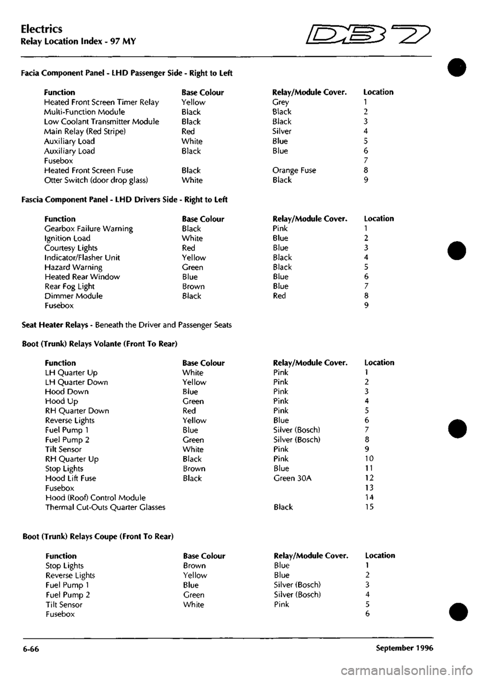
Electrics
Relay Location Index - 97 MY
D^^
Facia Component Panel
- LHD
Passenger
Function
Heated Front Screen Timer Relay
Multi-Function Module
Low Coolant Transmitter Module
Main Relay (Red Stripe)
Auxiliary Load
Auxiliary Load
Fusebox
Heated Front Screen Fuse
Otter Switch (door drop glass)
Side
-
Right
to
Left
Base Colour
Yellow
Black
Black
Red
White
Black
Black
White
Fascia Component Panel
- LHD
Drivers Side
-
Right
to
Left
Function
Gearbox Failure Warning
Ignition Load
Courtesy Lights
Indicator/Flasher Unit
Hazard Warning
Heated Rear Window
Rear
Fog
Light
Dimmer Module
Fusebox
Base Colour
Black
White
Red
Yellow
Green
Blue
Brown
Black
Relay/Module Cover.
Grey
Black
Black
Silver
Blue
Blue
Orange Fuse
Black
Relay/Module Cover.
Pink
Blue
Blue
Black
Black
Blue
Blue
Red
Location
1
2
3
4
5
6
7
8
9
Location
1
2
3
4
5
6
7
8
9
Seat Heater Relays - Beneath the Driver and Passenger Seats
Boot (Trunk) Relays Volante (Front To Rear)
Function
LH Quarter
Up
LH Quarter Down
Hood Down
Hood
Up
RH Quarter Down
Reverse Lights
Fuel Pump
1
Fuel Pump
2
Tilt Sensor
RH Quarter
Up
Stop Lights
Hood Lift Fuse
Fusebox
Hood (Roof) Control Module
Thermal Cut-Outs Quarter Glasses
Base Colour
White
Yellow
Blue
Green
Red
Yellow
Blue
Green
White
Black
Brown
Black
Relay/Module Cover.
Pink
Pink
Pink
Pink
Pink
Blue
Silver (Bosch)
Silver (Bosch)
Pink
Pink
Blue
Green
30A
Black
Location
1
2
3
4
5
6
7
8
9
10
11
12
13
14
15
Boot (Trunk) Relays Coupe (Front To Rear)
Function
Stop Lights
Reverse Lights
Fuel Pump 1
Fuel Pump 2
Tilt Sensor
Fusebox
Base Colour
Brown
Yellow
Blue
Green
White
6-66
Relay/Module
Blue
Blue
Silver (Bosch)
Silver (Bosch)
Pink
Cover. Location
1
2
3
4
5
6
September
1996
Page 150 of 421
COLUMN SWITCHGEAR NO COLOUR
PIN
670
B
671
BK
572
NR
71
NB
673
U
80
UW
674
GW
615
G
675
GR
676
LOR
677
LC
678
LGP
679 BP 680 LGN 681
LGW
G82
0
683 LOG 139
WU
58
PB
137
NU
1 7. 3 1 5 6 7 8 9 10 II 1? 1} 14 15 16 17 18 19 20
AREA
8.B4-67
I0.B2-9:
8.65-70
8.AI 9.A2 S.AI I0.B2-9I 8.C3
8.C2-79
II.B6 IO.BI-89 ILB6
9.83-81
II.B6
ii.Be
II.B4-I2I II.B6 8.CI 8.BI 8.BI
COURTESY LIGHT
ID
NO COLOUR PIN 684
PG
1 685
B
2 686 PW 3 687 P 4
AREA
8.B2-6I
8.B2-G2
9.01
8.B5-7I
SHEET 8 AREA B6
2K2 RESISTOR NO COLOUR PIN 692
U
A 673
U
6
AREA
9.83-83
9.AI 'AAAA-
lOL
ID]
(D
CRUISE DISABLE
8
STOP LAMP SWITCHES
[=r
NO COLOUR
PIN 693 8 I 694 LGY 2 127 YR 3 695
CB
4
AREA
8.B4-67
9.B5-82
8.BI IO.C3-I0I
DRIVERS AIRBAC
NO COLOUR
PIN 696 RP I 2 697
KN
3
AREA
II.C4-I20
NO COLOUR PIN AREA 688 U U
9.C2-76
689
U W
9.C5-86
NO COLOUR
PIN
690 RY
U
691
U W
AREA
9.C2-78
9.C5-86
^=^^1
[^1
SPL
77 SPL 79
I
I
INSTRUMENT PACK GREEN I T ,.
NO COLOUF 268 NB 726 RB 134 UW 727 GR 707 SW 196 KU 729 PS 264 OS 238 OK 752 LOO 733 W¥ 192 WS 325 WS 736 RIN 737 UIN 738 BRD
PIH 1 ? 3 4 5 6 7 8 9 10 II 12 13 14 15 16
AREA
12.
Al lO.CI 8.BI
9.C2-79
9.02 II.CI 1I.C3 I2.AI I2.AI
10.B2-97
9.B5-87
II.CI I2.A2 I0.C5 I0.C5 I2.C5-I03
INSTRUMENT PACK BLACK
-
SPL
83
-SPL
82
-SPL
81
NO COLOUR
PIN
AREA
720
GN
U
9.C4-85 721
OR W
9.C2-79
|F^
SPL
76 SPL 78
P.A.T.S. TRANSCEIVER DIMMER SWITCH
n
n/J D D II 11 II 11 II 11 D D II
1 1
u ul|,
NO COLOUf 739 BS 740 YW
741 GN 742 GW 743 GO 744 WU 745 BW 328 UG 747 BY
191 GB 611 OU 749 OU 610 OS 750 OS
PIN 1 2 3 4 5 6 7 8 9 10 II 12 13 14 15 16
AREA II.B3-I16 IO.B2-92
9.C4-85
I0.B2-9I I2.A5 I2.B2
I0.B2-9'
I2.AI
9.A5-88
ILBI 8.03 I2.DE 8.03 12.06
INSTRUMENT PACK WHITE
D D D D
CB D D D D • D
^
Tl
NO COLOUf 751
WK
752
P
753
GR
754
GY
755
B
756
B
757
RW
758
GU
759
GN
PIN 1
2 3
4
5 6 7 8 9
10 II 12
AREA
8.B5-73
1I.B4-I22
9.C6 9.C6
8.B4-67
8.B2-63
8.B4-68
9.C6 9.C6
DIAGNOSTIC SOCKET
NATURAL BASE
J¥tL
87A 87A
nifl
NO COLOUR
PIN
709
W
1
710
B 2
7H
UW 3
712
OB 4
AREA I2.BI I2.BI
I2BI I2.BI
BLACK BASE
COURTESY HO COLOUR 698 6U 699 P 700
PW
686
PW
LIGHT RELAY PIN AREA 85 I1.B4-I27 86
8.B5-7I
87
8.83-65
87A 30 9.BI
AUX LOAD RELAY NO COLOUR 701 B 702
WK
703
WO
704
N
PIN 85 86 8/ 87A 30
AREA
8.B2-62
9.C2-77
8.B5-72
I0.A2
GEARBOX WARNING NO COLOUR 182
S
706
WK
"
707 SW 708
WK
PIN AREA 85 II.BI 86
8.85-73
87
87A
9.A4
30
8.B5-73
l>°
l>«'
l>»'
ll">'
l>-'
l>='
'
6
NO COLOUR PIN 1 2 3 629
K
4 627 0 5 628 R 6
AREA
8.C5 8.C5 8.C5
NO COLOUR PIN 753
GR
1 754 OY 2 758
GU
3 759
GN
4
AREA 9.B6 9.66 9.B6 9.B6
KEY SOLENOID KEY-IN WARNING SWITCH NO COLOUR PIN AREA
713
YN I 1LC3
714
YB 2
II.C3
NO COLOUR
PIN
AREA 715
PG I 12.A5
716
a 2
8.62-63
GNITION SWITCH NO COLOUR
717 718 84 719
N WK WY W
PIN 1 ? 3 4
AREA I0.A2
9.C2-77
8.AI
8.66-74
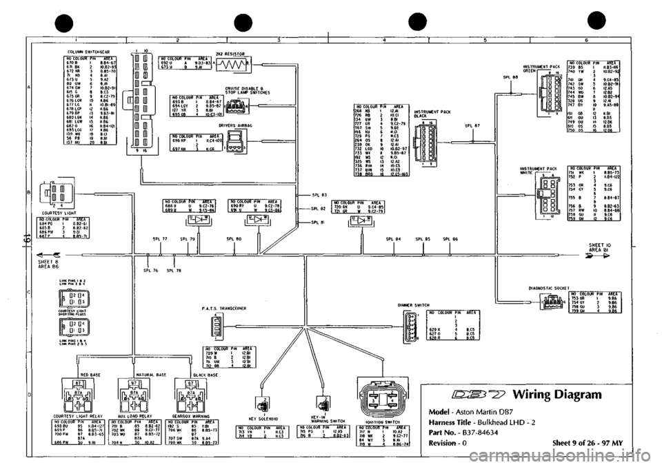
"^3? wiring Diagram
Model - Aston Martin DB7
Harness Title - Bulkhead LHD - 2
Part No. - 837-84634
Revision - 0 Sheet 9 of 26 - 97 MY
Page 156 of 421
in
NO COLOUF 711 UW
842 KB
836 8G
924 UIN
923 RIN
710 B 769 KB 709 W
925 N
712 OB 709 B
920 W
PIN 1 ? 3 4 5 6 1 8 9 1(1 II 1? 13 14 15 16 17 IS 19 20
ARE*
9.02
11X3
II.C3
I2.A3
I2.A3
9.02 10.01 9.02
II.B4-I23
9.02 I2.CI-I3I
I2.C2-I36
NO COLOUI 297 NS 294 R 304 YB 238 OK 325 WS 264 OS 268 NB 326 UIN 327 RIN 328 UG 13 RO 330 LGO 135 OY 54 C 333 P 334 KB 155 KB 290 KB 335 OB 336 0 337 RN 338 OY 339 m 340 OG
PIN 1 2 3 4 5 6 / 8 9 10 II 12 13 14 15 16 {I 18 19 20 21 22 23 24
AREA II.A3 10.04 10.04 9.A4 9.A4 9.A4 9.A4 I0.C5 I0.C5 9.A6 B.BI 10.04 B.BI B.BI ILB4-I22 I2.C2-I3; ii.a-lil 12.C2-I3; 10.04 10.04 10.04 10.01 II.Al lo.n
• SHEET 6 • AREA B/C2
D
• 0 0
a
D
DOd-,
0 D
1—
D D
n:
a a *— D • • D
o[nr 0 0 • G
a
•
•••npaa
ENGINE HARNESS
SHEET 6 AREA C4
NO COLOUf 341 BRD 926 BRD 186 BY 187 BU 189 SP 344 RIN 923 RIN 345 8G 346 UIN 924 UIN 194 YG 198 RN 348 YU 927 LGO 809 YH 316 B
PIN 1 I •/ 3 4 5 5 6 7 7 8 9 10 II 1? 13
AREA 12.82-132 10.83-112 II.BI II.BI II.BI 10.A4 I2.AI I0.B5-I06 I0.A4 I2.BI II.CI II.CI I0.A4 I0.B2-97 10.04 I0.A4
RED FOWARD 12 I
^
SHEET 3 AREA B6
NO COLOUf ISO
181
138 178 149
163
145
147
GW
NS
YR BK WR
GN
LGB
BS
PIN 1 2 3 4 5 6 1 8 9 10 II 12 13 14 15 16 17 18 19 20
AREA 10.82-91
11.Al
8.BI I2.C2-I4C I2.B2
CI.CI
11.86
M.B2-II6
NO COLOUf 932 B 933 BR 934 BS 935 W 936 NR
937 P 623 BC 938 BS 939 BY 715 PO 940 BP 854 WB 808 K 839 W>
941 BU 743 GO 942 BW 838 PS
PIN 1 ? 3 4 5 6 7 8 9 10 H 1? 13 14 15 16 17 18 19 20
AREA 12.03-143 I0.B2-96 I2C3-I46 I2.C2-I36
8.B5-70
I2.C2-I39 8.C4 II.B2-II6
9.A5-88
9.03
8.C2-60
11.03 10.04 1I.C3
II.B5-I27 9.Ae IO.B2-94 II.C3
AiR8&G SENSOR
MULTIFUNCTION MODULE
ir='fn)—II,
NO COLOUR PIN 866 ON I 873
KU
2 3 863 OP 4 II.C6
AREA II.C6 II.C6
DOOR HAflNESS SHEET 22 ;^ 1>. AREA B6 "^ *^ NO COLOUf 981 99? 983 984
986 987 988 989 818 819 381 38? 383
990 991 99? 99.1 994
OG OU OW OR
6 BW PG PW RG GR YG YU Y
LG NU BS RN B
PIN 1 2 3 4 5 6 7 8 9 10 11 12 13 14 15 16 If 18 19 20 21 22
AREA I2.C4-I4S 12.C3-I4S l2.C4-l4t 12.C3-I47
I2.C2-I37 I2.C3-I4I
8.82-61
8.83-65
I2.C2-I34 11.01 8.01 8.01 8.DI
8.B5-69
I2.C2-135 I2.C3-I46 IO.B5-I07 I2.C3-I42
NO COLOUt 891 NK
995 RW 996 PN
909 NG 997 BS 998 WK 904 OW 750 OS 749 OU 999 BK
PIN 1 2 3 4 5 6 7 8 9 10 11 1? 13 14 15 16
AREA
11.
Al
II.B2-1I4 11.82-113
ILA3 I2.C3-I46 II.B3-II7 II.AI 9.A6 9.A6 I2.C2-I40
LOAD RELAY NO COLOUR 94 7 B 948 W 949 W
950
N
PIN 85 86 87 87A 30
AREA I2.C2-I4;
e.B6-74
I2.C1-I29
II.A5-I25
AUX LOAD RELAY NO COLOUB 951 B 952
WK
953
WK
954
N
PIN 8.5 86 87 87A 30
AREA I2.C3-I42 II.B5-I17 11.85-128
II.B4-123
NO COLOUB 955 8 956
WR
957
KB
958
KB
899 NP
PIN 85 86 87 87A 30
AREA
B.B4-67
12.C2-I38 12.C2-I33 10.84-104 II.AI
HO COLOUR 959
BK
960 W 889 N 961 NY
PIN 85 86 8/ 30
AREA 10.85-10! I2.CI-I29 II.A6 I2.C3-I44
NO COLOUE 972 OG 973 OW 974 P 975 BK 976 W 977 OR 978 OU
PIN 1 2 3 4 5 6 7 8 9 10 II 12 13 14
AREA I2.C4-I49 l2.C4-l4t I2.C2-I39 I2.C2-I40 I2.C2-I36 I2.C3-I47 12.C3-145
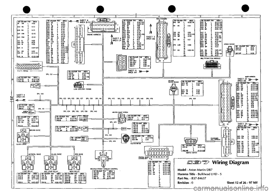
Wiring Diagram
Model - Aston Martin DB7
Harness Title - Bulkhead LHD
Part No. - B3
7-8463
7
Revision - 0 Sheet 12 of 26-97 MY
Page 194 of 421
Electrics
Airbag System '=2?
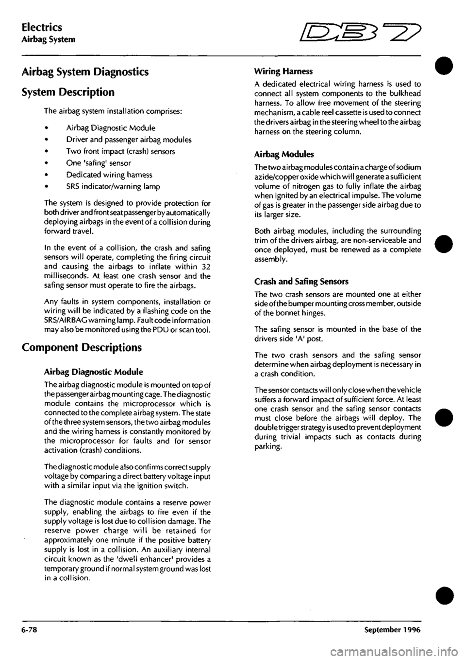
Airbag System Diagnostics
System Description
The airbag system installation comprises:
Airbag Diagnostic Module
Driver and passenger airbag modules
Two front impact (crash) sensors
One 'safing' sensor
Dedicated wiring harness
SRS indicator/warning lamp
The system is designed to provide protection for
both driver and front seat passenger by automatical ly
deploying airbags in the event of
a
collision during
forward travel.
In the event of a collision, the crash and safing
sensors will operate, completing the firing circuit
and causing the airbags to inflate within 32
milliseconds. At least one crash sensor and the
safing sensor must operate to fire the airbags.
Any faults in system components, installation or
wiring will be indicated by a flashing code on the
SRS/AIRBAG warning lamp. Fault code information
may also be monitored using the PDU or scan
tool.
Component Descriptions
Airbag Diagnostic Module
The airbag diagnostic module is mounted on top of
the passenger airbag mountingcage.Thediagnostic
module contains the microprocessor which is
connected to the complete airbag system. The state
of the three system sensors, the two airbag modules
and the wiring harness is constantly monitored by
the microprocessor for faults and for sensor
activation (crash) conditions.
The diagnostic module also confirms correct supply
voltage by comparing
a
direct battery voltage input
with a similar input via the ignition switch.
The diagnostic module contains a reserve power
supply, enabling the airbags to fire even if the
supply voltage is lost due to collision damage. The
reserve power charge will be retained for
approximately one minute if the positive battery
supply is lost in a collision. An auxiliary internal
circuit known as the 'dwell enhancer' provides a
temporary ground if normal system ground was lost
in a collision.
Wiring Harness
A dedicated electrical wiring harness is used to
connect all system components to the bulkhead
harness. To allow free movement of the steering
mechanism, a cable reel cassette is used to connect
the drivers airbag in the steering wheel to the airbag
harness on the steering column.
Airbag Modules
The two airbag modules contain achargeof sodium
azide/copper oxide which wi
11
generate
a
sufficient
volume of nitrogen gas to fully inflate the airbag
when ignited by an electrical impulse. The volume
of gas is greater in the passenger side airbag due to
its larger size.
Both airbag modules, including the surrounding
trim of the drivers airbag, are non-serviceable and
once deployed, must be renewed as a complete
assembly.
Crash and Safing Sensors
The two crash sensors are mounted one at either
side of the bumper mounting cross member, outside
of the bonnet hinges.
The safing sensor is mounted in the base of the
drivers side 'A' post.
The two crash sensors and the safing sensor
determine when airbag deployment is necessary in
a crash condition.
The sensor contacts will only close when the vehicle
suffers a forward impact of sufficient force. At least
one crash sensor and the safing sensor contacts
must close before the airbags will deploy. The
doubletrigger strategy
is
used to prevent deployment
during trivial impacts such as contacts during
parking.
6-78 September 1996
Page 292 of 421
Air Conditioning
Functional Check
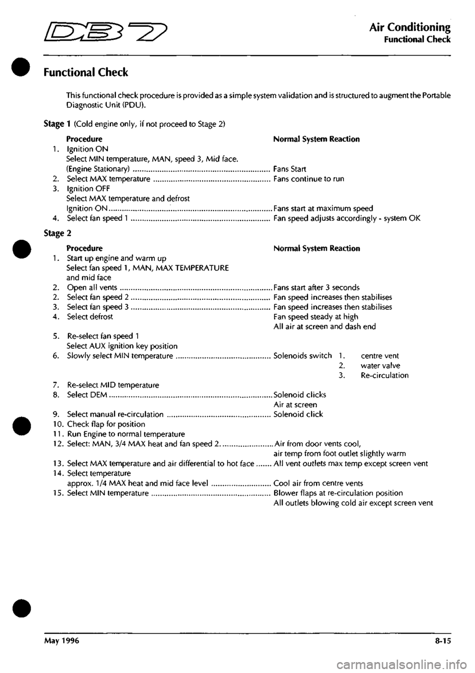
Functional Check
This functional check procedure is provided as a simple system validation and is structured to augment the Portable
Diagnostic Unit (PDU).
Stage 1 (Cold engine only, if not proceed to Stage 2)
Procedure Normal System Reaction
1.
Ignition ON
Select MIN temperature, MAN, speed 3, Mid face.
(Engine Stationary) Fans Start
2.
Select MAX temperature Fans continue to run
3. Ignition OFF
Select MAX temperature and defrost
Ignition ON Fans start at maximum speed
4.
Select fan speed
1
Fan speed adjusts accordingly - system OK
Stage 2
Procedure Normal System Reaction
1.
Start up engine and warm up
Select fan speed 1, MAN, MAX TEMPERATURE
and mid face
2.
Open all vents Fans start after 3 seconds
2.
Select fan speed 2 Fan speed increases then stabilises
3. Select fan speed 3 Fan speed increases then stabilises
4.
Select defrost Fan speed steady at high
All air at screen and dash end
5. Re-select fan speed 1
Select AUX ignition key position
6. Slowly select MIN temperature Solenoids switch 1. centre vent
2.
water valve
3. Re-circulation
7. Re-select MID temperature
8. Select DEM Solenoid clicks
Air at screen
9. Select manual re-circulation Solenoid click
10.
Check flap for position
11.
Run Engine to normal temperature
12.
Select: MAN, 3/4 MAX heat and fan speed 2 Air from door vents
cool,
air temp from foot outlet slightly warm
13.
Select MAX temperature and air differential to hot face All vent outlets max temp except screen vent
14.
Select temperature
approx. 1/4 MAX heat and mid face level Cool air from centre vents
15.
Select MIN temperature Blower flaps at re-circulation position
All outlets blowing cold air except screen vent
May 1996 8-15
Page 297 of 421
Air Conditioning
Electronic Control Module r^^?
Description
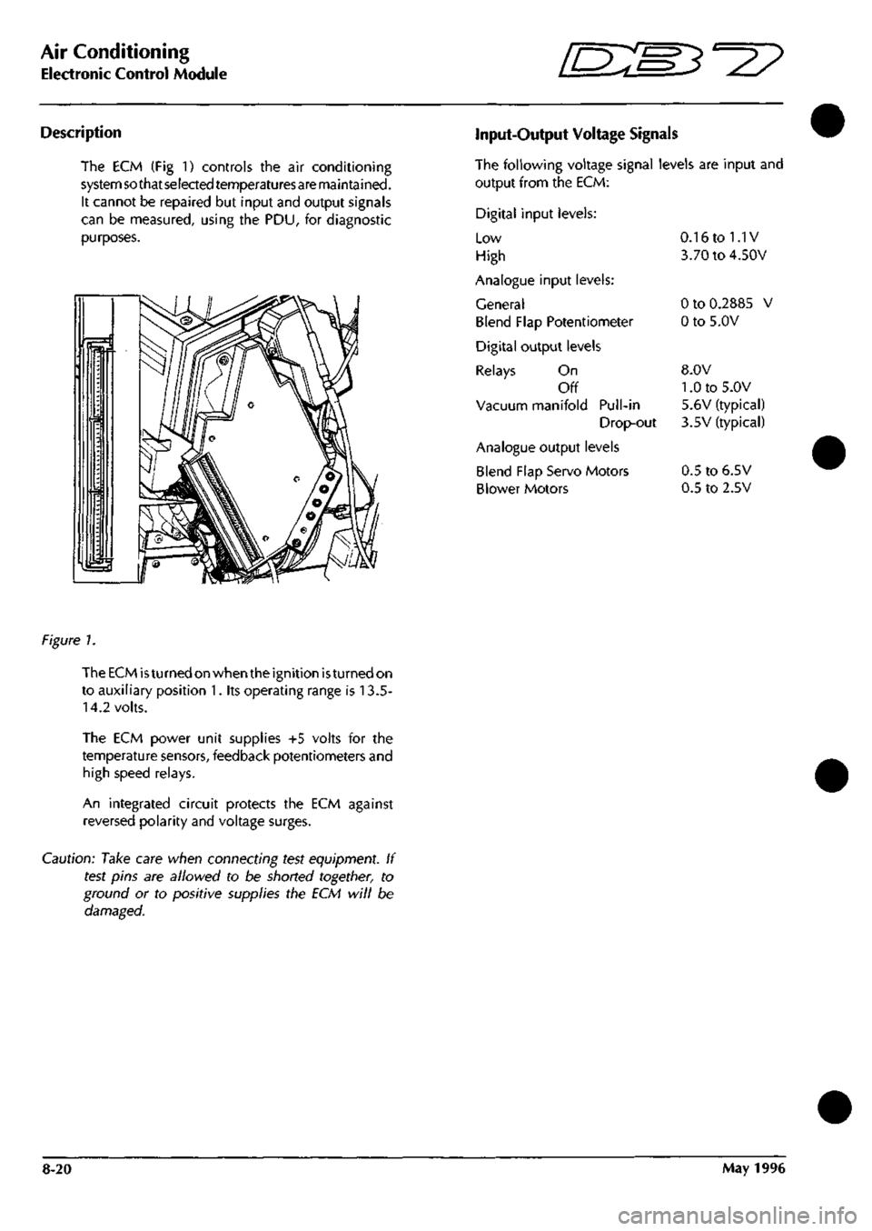
The ECM (Fig 1) controls the air conditioning
system so that selected temperaturesare maintained.
It cannot be repaired but input and output signals
can be measured, using the PDU, for diagnostic
purposes.
Input-Output Voltage Signals
The following voltage signal levels are input and
output from the ECM:
Digital input levels:
Low
High
Analogue input levels:
General
Blend Flap Potentiometer
Digital output levels
Relays On
Off
Vacuum manifold Pull-in
Drop-out
Analogue output levels
Blend Flap Servo Motors
Blower Motors
0.16 to 1.1V
3.70 to 4.50V
0 to 0.2885 V
0 to 5.0V
8.0V
1.0 to 5.0V
5.6V (typical)
3.5V (typical)
0.5 to 6.5V
0.5 to 2.5V
figure 1.
The ECM
is
turned on when the ignition
is
turned on
to auxiliary position 1. its operating range is 13.5-
14.2 volts.
The ECM power unit supplies +5 volts for the
temperature sensors, feedback potentiometers and
high speed relays.
An integrated circuit protects the ECM against
reversed polarity and voltage surges.
Caution: Take care when connecting test equipment. If
test pins are allowed to be shorted together, to
ground or to positive supplies the ECM will be
damaged.
8-20 May 1996