climate control ASTON MARTIN DB7 1997 Workshop Manual
[x] Cancel search | Manufacturer: ASTON MARTIN, Model Year: 1997, Model line: DB7, Model: ASTON MARTIN DB7 1997Pages: 421, PDF Size: 9.31 MB
Page 278 of 421
in:!M3^^?
Air Conditioning
Contents
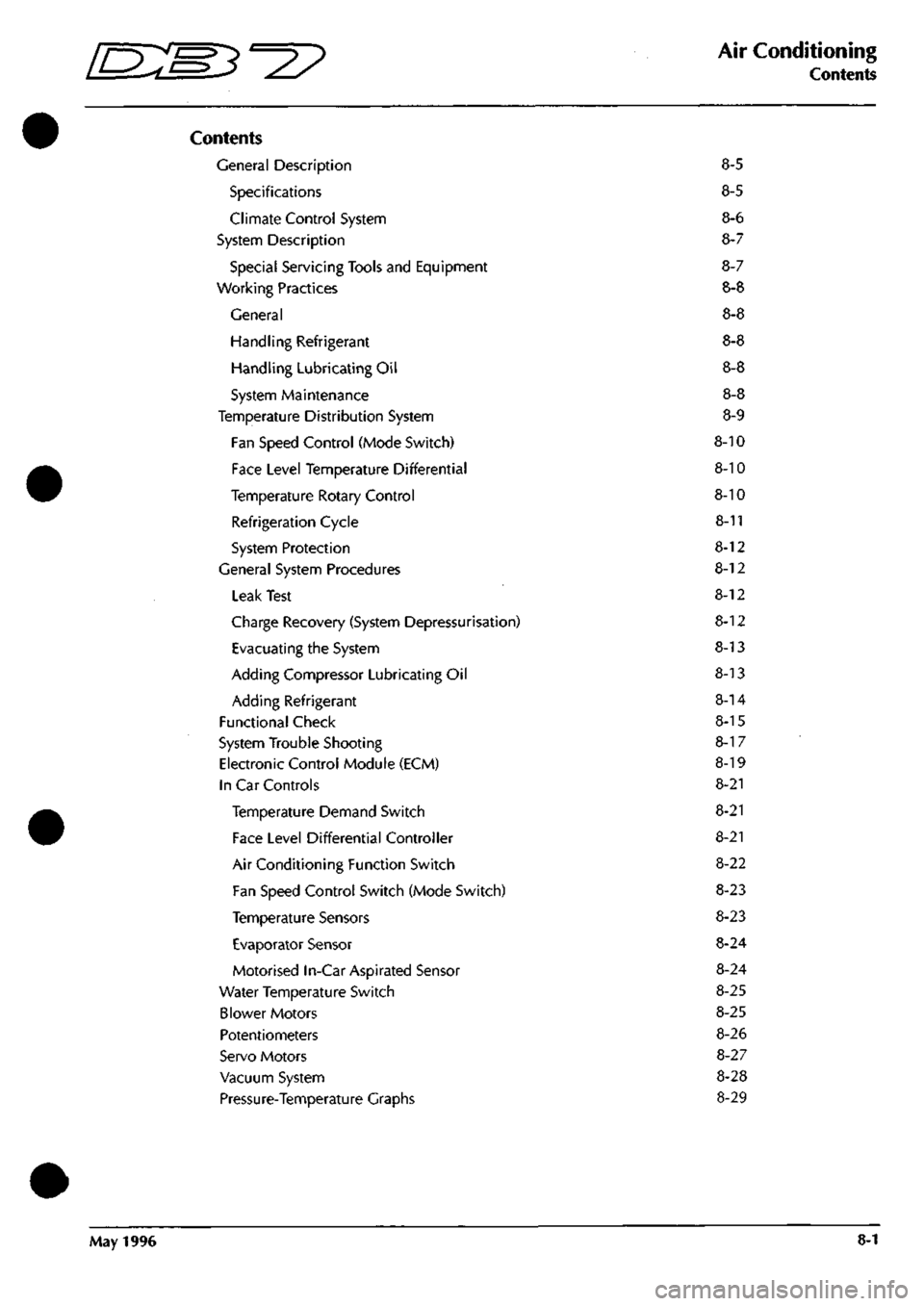
Contents
General Description 8-5
Specifications 8-5
Climate Control System 8-6
System Description 8-7
Special Servicing Tools and Equipment 8-7
Working Practices 8-8
General 8-8
Handling Refrigerant 8-8
Handling Lubricating Oil 8-8
System Maintenance 8-8
Temperature Distribution System 8-9
Fan Speed Control (Mode Switch) 8-10
Face Level Temperature Differential 8-10
Temperature Rotary Control 8-10
Refrigeration Cycle 8-11
System Protection 8-12
General System Procedures 8-12
Leak Test 8-12
Charge Recovery (System Depressurisation) 8-12
Evacuating the System 8-13
Adding Compressor Lubricating Oil 8-13
Adding Refrigerant 8-14
Functional Check 8-15
System Trouble Shooting 8-1 7
Electronic Control Module (ECM) 8-19
In Car Controls 8-21
Temperature Demand Switch 8-21
Face Level Differential Controller 8-21
Air Conditioning Function Switch 8-22
Fan Speed Control Switch (Mode Switch) 8-23
Temperature Sensors 8-23
Evaporator Sensor 8-24
Motorised In-Car Aspirated Sensor 8-24
Water Temperature Switch 8-25
Blower Motors 8-25
Potentiometers 8-26
Servo Motors 8-27
Vacuum System 8-28
Pressure-Temperature Graphs 8-29
May 1996 8-1
Page 283 of 421
Air Conditioning
General Description 5^^?
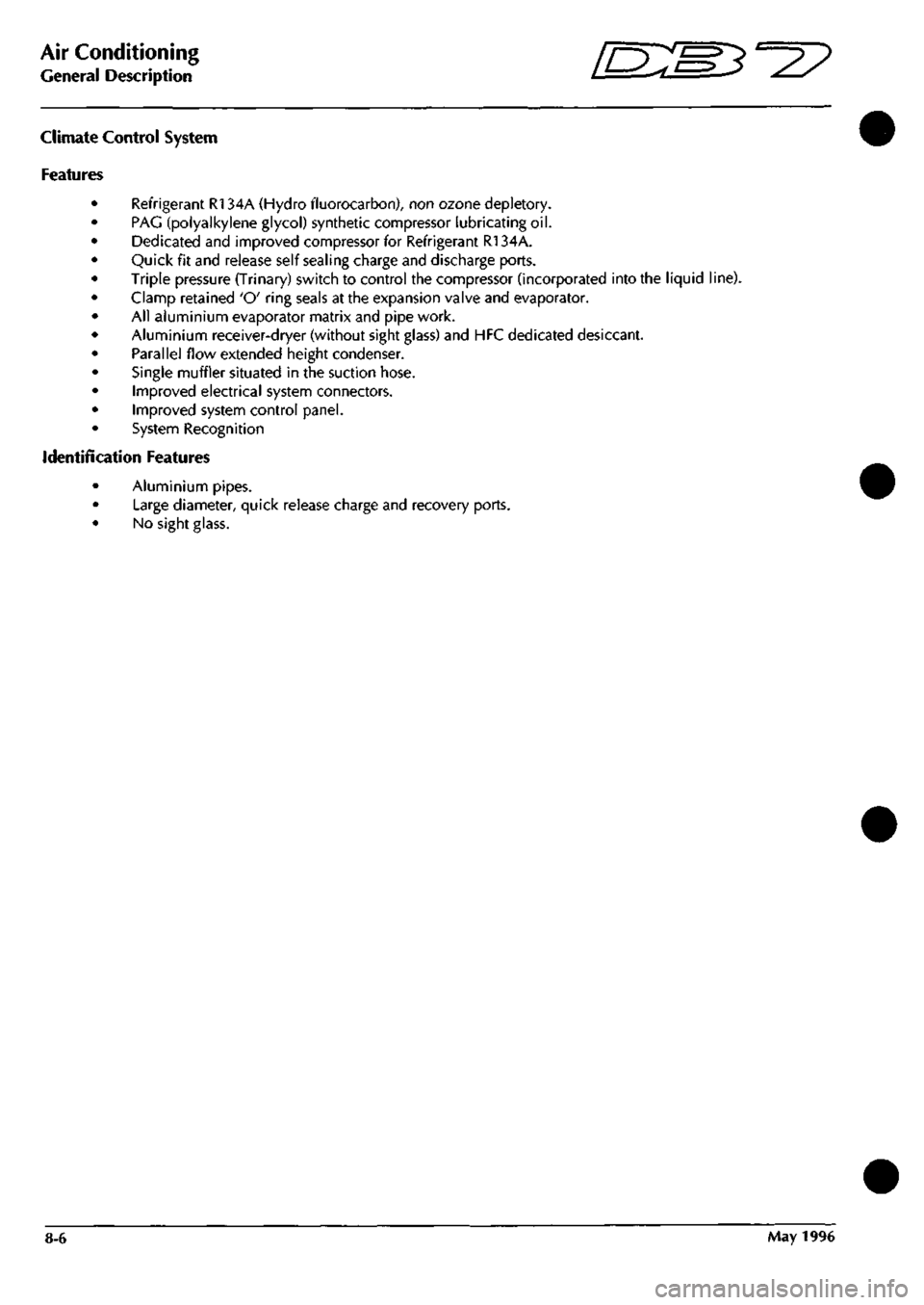
climate Control System
Features
Refrigerant R134A (Hydro fluorocarbon), non ozone depletory.
PAG (polyalkylene glycol) synthetic compressor lubricating oil.
Dedicated and improved compressor for Refrigerant R134A.
Quick fit and release self sealing charge and discharge ports.
Triple pressure (Trinary) switch to control the compressor (incorporated into the liquid line).
Clamp retained 'O' ring seals at the expansion valve and evaporator.
All aluminium evaporator matrix and pipe work.
Aluminium receiver-dryer (without sight glass) and HFC dedicated desiccant.
Parallel flow extended height condenser.
Single muffler situated in the suction hose.
Improved electrical system connectors.
Improved system control panel.
System Recognition
Identification Features
Aluminium pipes.
Large diameter, quick release charge and recovery ports.
No sight glass.
8-6 May 1996
Page 352 of 421
^?
The Aston Martin Lagonda Diagnostic System
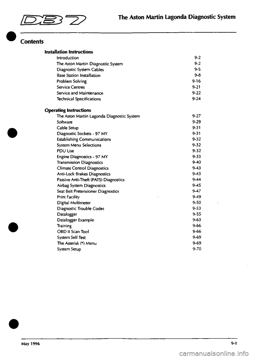
Contents
Installation Instructions
Introduaion 9-2
The Aston Martin Diagnostic System 9-2
Diagnostic System Cables 9-5
Base Station Installation 9-8
Problem Solving 9-16
Service Centres 9-21
Service and Maintenance 9-22
Technical Specifications 9-24
Operating Instructions
The Aston Martin Lagonda Diagnostic System 9-27
Software 9-29
Cable Setup 9-31
Diagnostic Sockets - 97 MY 9-31
Establishing Communications 9-32
System Menu Selections 9-32
PDU Use 9-32
Engine Diagnostics - 97 MY 9-33
Transmission Diagnostics 9-40
Climate Control Diagnostics 9-43
Anti-Lock Brakes Diagnostics 9-43
Passive Anti-Theft (PATS) Diagnostics 9-44
Airbag System Diagnostics 9-45
Seat Belt Pretensioner Diagnostics 9-47
Print Facility 9-49
Digital Multimeter 9-50
Diagnostic Trouble Codes 9-53
Datalogger 9-55
Datalogger Example 9-63
Training 9-66
OBD II Scan Tool 9-66
System Self Test 9-69
The Asterisk (*) Menu 9-69
System Setup 9-70
May 1996 9-1
Page 379 of 421
The Aston Martin Lagonda Diagnostic System
Users Guide o: "3^^?
PDU Functions
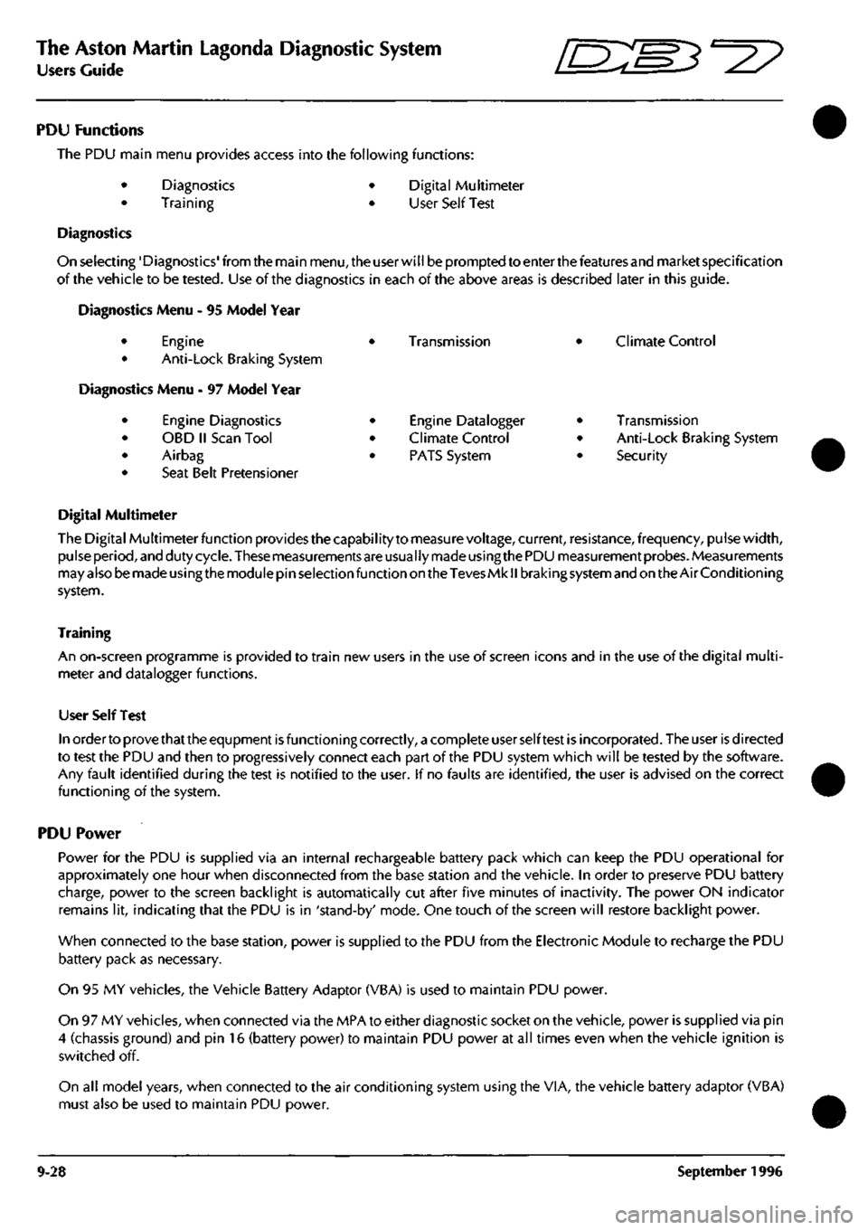
The PDU main menu provides access into the following functions:
Diagnostics
Training
Digital Multimeter
User Self Test
Diagnostics
On selecting'Diagnostics'from the main
menu,
the user will be prompted to enter the features and market specification
of the vehicle to be tested. Use of the diagnostics in each of the above areas is described later in this guide.
Diagnostics Menu - 95 Model Year
Engine
Anti-Lock Braking System
Vlenu - 97 Model Year
Engine Diagnostics
OBD II Scan Tool
Airbag
Seat Belt Pretensioner
•
•
•
•
Transmission
Engine Datalogger
Climate Control
PATS System
Climate Control
Transmission
Anti-Lock Braking System
Security
Digital Multimeter
The Digital Multimeter function provides the capabilityto measure voltage, current, resistance, frequency, pulse width,
pulse period, and duty cycle. These measurements are usually made using the PDU measurement probes. Measurements
may also be made using the module pin selection function on the Teves Mk
II
braking system and on the Air Conditioning
system.
Training
An on-screen programme is provided to train new users in the use of screen icons and in the use of the digital multi
meter and datalogger functions.
User Self Test
In order to prove that the equpment is functioning correctly, a complete user self test is incorporated. The user is directed
to test the PDU and then to progressively connect each part of the PDU system which will be tested by the software.
Any fault identified during the test is notified to the user. If no faults are identified, the user is advised on the correct
functioning of the system.
PDU Power
Power for the PDU is supplied via an internal rechargeable battery pack which can keep the PDU operational for
approximately one hour when disconnected from the base station and the vehicle. In order to preserve PDU battery
charge, power to the screen backlight is automatically cut after five minutes of inactivity. The power ON indicator
remains lit, indicating that the PDU is in 'stand-by' mode. One touch of the screen will restore backlight power.
When connected to the base station, power is supplied to the PDU from the Electronic Module to recharge the PDU
battery pack as necessary.
On 95 MY vehicles, the Vehicle Battery Adaptor (VBA) is used to maintain PDU power.
On 97 MY vehicles, when connected via the MPA to either diagnostic socket on the vehicle, power is supplied via pin
4 (chassis ground) and pin 16 (battery power) to maintain PDU power at all times even when the vehicle ignition is
switched off.
On all model years, when connected to the air conditioning system using the VIA, the vehicle battery adaptor (VBA)
must also be used to maintain PDU power.
9-28 September 1996
Page 381 of 421
The Aston Martin Lagonda Diagnostic System
Users Guide D-^?
Vehicle Features
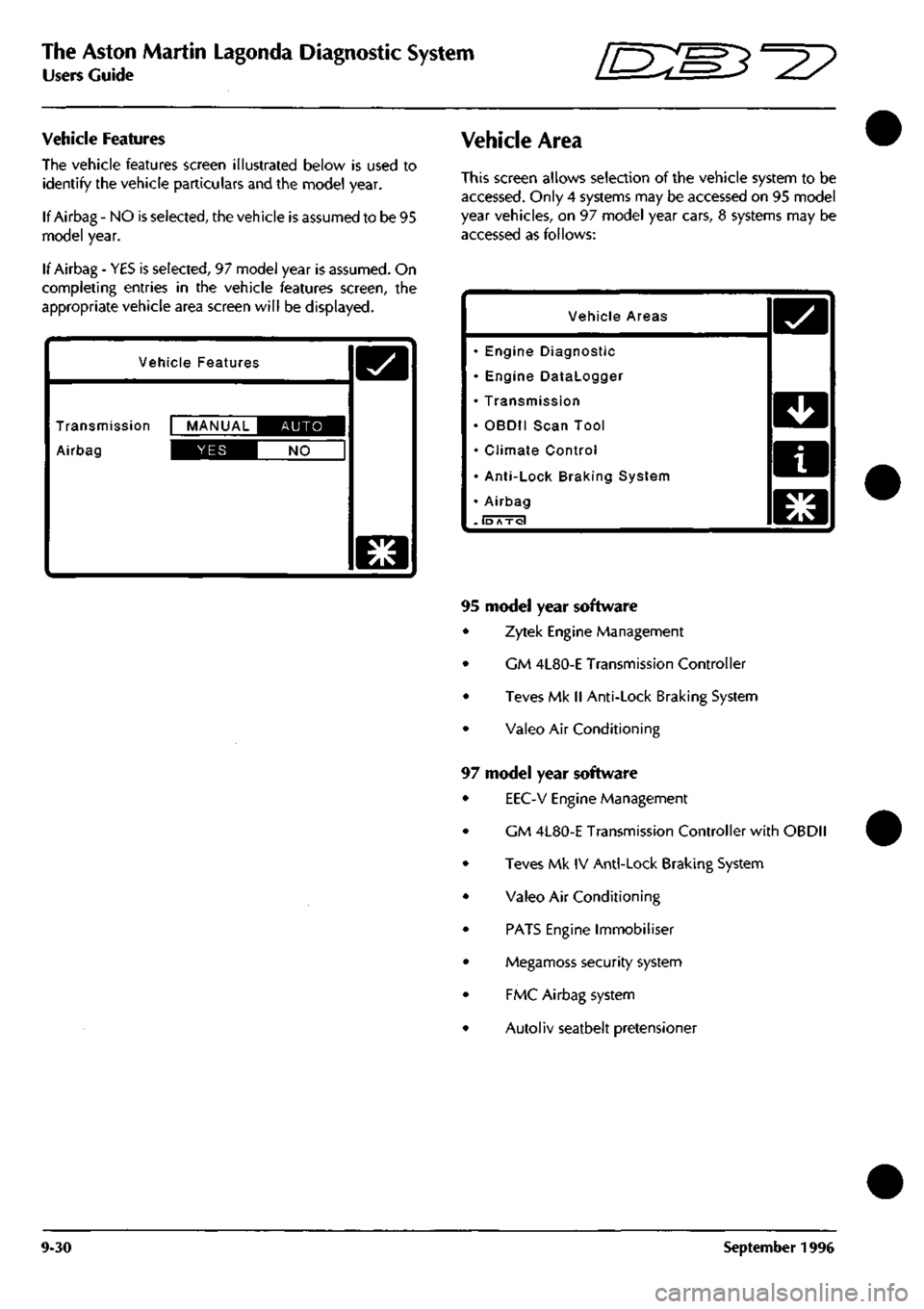
The vehicle features screen illustrated below is used to
identify the vehicle particulars and the model year.
If Airbag - NO is selected, the vehicle is assumed to be 95
model year.
If Airbag - YES is selected, 97 model year is assumed. On
completing entries in the vehicle features screen, the
appropriate vehicle area screen will be displayed.
Vehicle Features
Transmission MANUAL IIBIE^^I
Airbag IDS^I NO
D
Vehicle Area
This screen allows selection of the vehicle system to be
accessed.
Only 4 systems may be accessed on 95 model
year vehicles, on 97 model year cars, 8 systems may be
accessed as follows:
Vehicle Areas
• Engine Diagnostic
• Engine Datalogger
• Transmission
• OBDII Scan Tool
• Climate Control
• Anti-Lock Braking System
• Airbag
. lb Axol
o
PI
mLM
n
WLM
El
Ku^
95 model year software
Zytek Engine Management
GM 4L80-E Transmission Controller
Teves Mk II Anti-Lock Braking System
Valeo Air Conditioning
97 model year software
EEC-V Engine Management
CM 4L80-E Transmission Controller with OBDII
Teves Mk IV Anti-Lock Braking System
Valeo Air Conditioning
PATS Engine Immobiliser
Megamoss security system
FMC Airbag system
Autoliv seatbelt pretensioner
9-30 September 1996
Page 383 of 421
The Aston Martin Lagonda Diagnostic System
Users Guide "^7
Establishing Communications
when cable connections are completed, switch on the
vehicle ignition. The electronic control units will 'wake
up'
and communication between the selected control unit
and the PDU will be established.
As communication
is
established with the selected system,
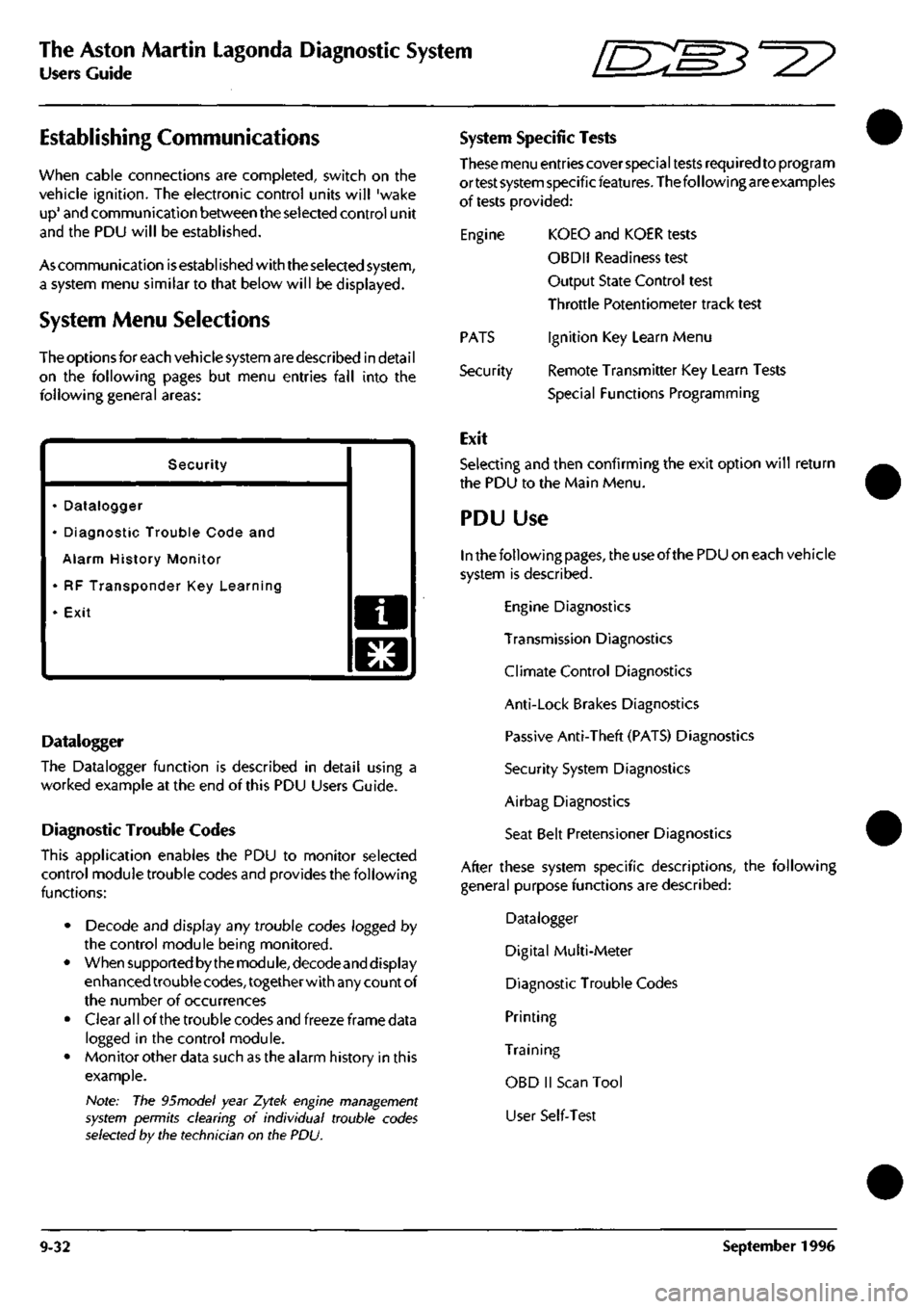
a system menu similar to that below will be displayed.
System Menu Selections
The options for each vehicle system are described in detai
I
on the following pages but menu entries fall into the
following general areas:
Security
• Datalogger
• Diagnostic Trouble Code and
Alarm History Monitor
• RF Transponder Key Learning
• Exit a
o
Datalogger
The Datalogger function is described in detail using a
worked example at the end of this PDU Users Guide.
Diagnostic Trouble Codes
This application enables the PDU to monitor selected
control module trouble codes and provides the following
functions:
• Decode and display any trouble codes logged by
the control module being monitored.
• When supported by the module, decodeand display
enhanced trouble
codes,
together with any count of
the number of occurrences
• Clear all of the trouble codes and freeze frame data
logged in the control module.
• Monitor other data such as the alarm history in this
example.
Note: The 95model year Zytek engine management
system permits clearing of individual trouble codes
selected by the technician on the PDU.
System Specific Tests
These menu entries cover special tests required to program
ortest system specificfeatures. The following are examples
of tests provided:
Engine KOEO and KOER tests
OBDII Readiness test
Output State Control test
Throttle Potentiometer track test
Ignition Key Learn Menu
Remote Transmitter Key Learn Tests
Special Functions Programming
PATS
Security
Exit
Selecting and then confirming the exit option will return
the PDU to the Main Menu.
PDU Use
In the following
pages,
the use of the PDU on each vehicle
system is described.
Engine Diagnostics
Transmission Diagnostics
Climate Control Diagnostics
Anti-Lock Brakes Diagnostics
Passive Anti-Theft (PATS) Diagnostics
Security System Diagnostics
Airbag Diagnostics
Seat Belt Pretensioner Diagnostics
After these system specific descriptions, the following
general purpose functions are described:
Datalogger
Digital Multi-Meter
Diagnostic Trouble Codes
Printing
Training
OBD II Scan Tool
User Self-Test
9-32 September 1996
Page 394 of 421
^?
The Aston Martin Lagonda Diagnostic System
Users Guide
Climate Control Diagnostics
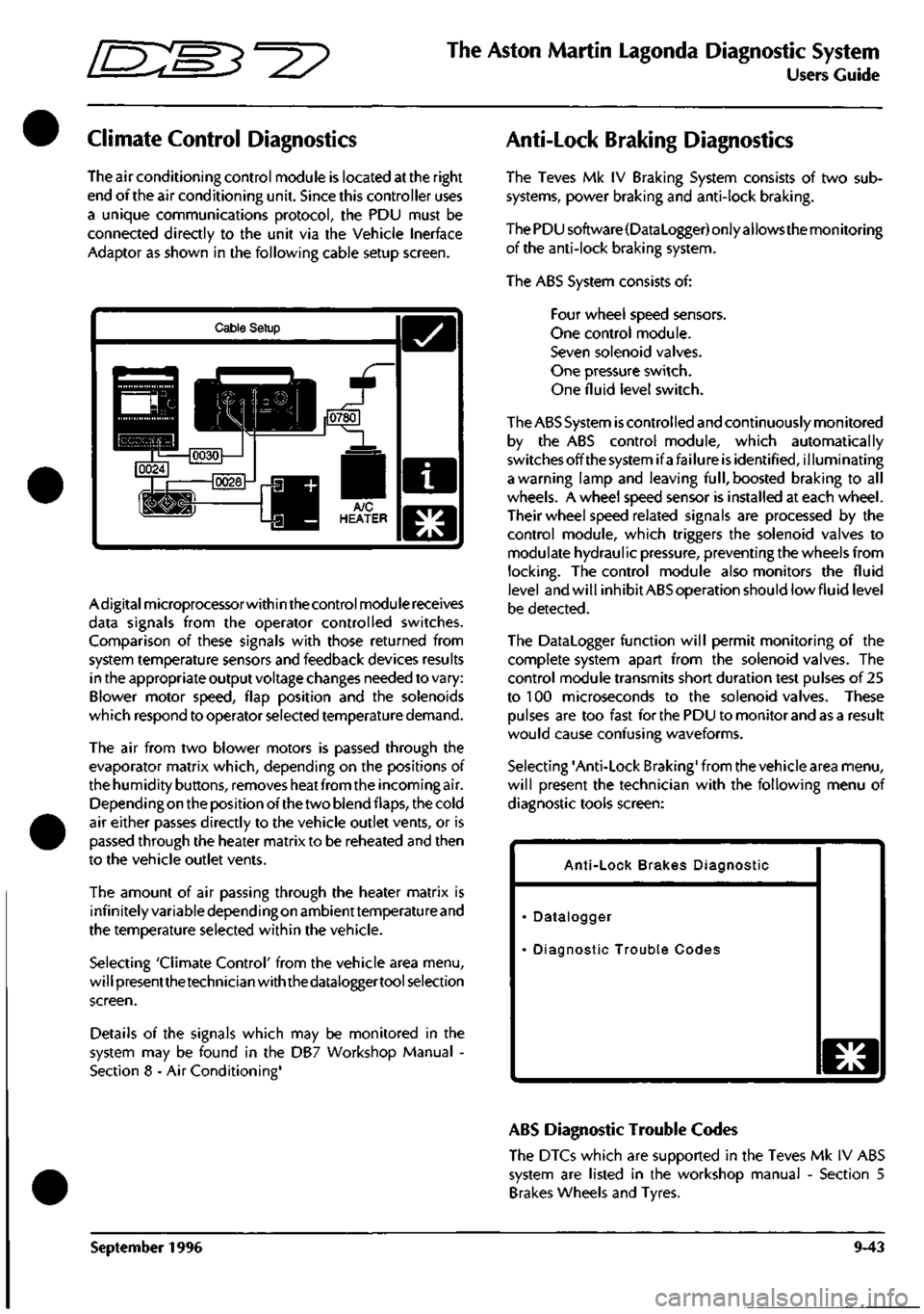
The air conditioning control module is located at the right
end of the air conditioning unit. Since this controller uses
a unique communications protocol, the PDU must be
connected directly to the unit via the Vehicle Inerface
Adaptor as shown in the following cable setup screen.
Cable Setup
Adigitalmicroprocessorwithin the control module receives
data signals from the operator controlled switches.
Comparison of these signals with those returned from
system temperature sensors and feedback devices results
in the appropriate output voltage changes needed to vary:
Blower motor speed, flap position and the solenoids
which respond to operator selected temperature demand.
The air from two blower motors is passed through the
evaporator matrix which, depending on the positions of
the humidity buttons, removes heat from the incoming air.
Dependingon the position of the two blend flaps, the cold
air either passes directly to the vehicle outlet vents, or is
passed through the heater matrix to be reheated and then
to the vehicle outlet vents.
The amount of air passing through the heater matrix is
infinitely variable depending on ambienttemperature and
the temperature selected within the vehicle.
Selecting 'Climate Control' from the vehicle area menu,
will presentthetechnician with the dataloggertool selection
screen.
Details of the signals which may be monitored in the
system may be found in the DB7 Workshop Manual -
Section 8 - Air Conditioning'
Anti-Lock Braking Diagnostics
The Teves Mk IV Braking System consists of two sub
systems, power braking and anti-lock braking.
The PDU software(DataLogger) only allows the monitoring
of the anti-lock braking system.
The ABS System consists of:
Four wheel speed sensors.
One control module.
Seven solenoid valves.
One pressure switch.
One fluid level switch.
The ABS System
is
controlled and continuously monitored
by the ABS control module, which automatically
switchesoffthesystemifafailure is identified, illuminating
a warning lamp and leaving
full,
boosted braking to all
wheels. A wheel speed sensor is installed at each wheel.
Their wheel speed related signals are processed by the
control module, which triggers the solenoid valves to
modulate hydraulic pressure, preventing the wheels from
locking.
The control module also monitors the fluid
level and will inhibit ABS operation should lowfluid level
be detected.
The Datalogger function will permit monitoring of the
complete system apart from the solenoid valves. The
control module transmits short duration test pulses of 25
to 100 microseconds to the solenoid valves. These
pulses are too fast for the PDU to monitor and as a result
would cause confusing waveforms.
Selecting 'Anti-Lock Braking' from the vehicle area menu,
will present the technician with the following menu of
diagnostic tools screen:
Anti-Lock Brakes Diagnostic
Datalogger
Diagnostic Trouble Codes
o
ABS Diagnostic Trouble Codes
The DTCs which are supported in the Teves Mk IV ABS
system are listed in the workshop manual - Section 5
Brakes Wheels and Tyres.
September 1996 9-43