coolant level ASTON MARTIN DB7 1997 Workshop Manual
[x] Cancel search | Manufacturer: ASTON MARTIN, Model Year: 1997, Model line: DB7, Model: ASTON MARTIN DB7 1997Pages: 421, PDF Size: 9.31 MB
Page 28 of 421
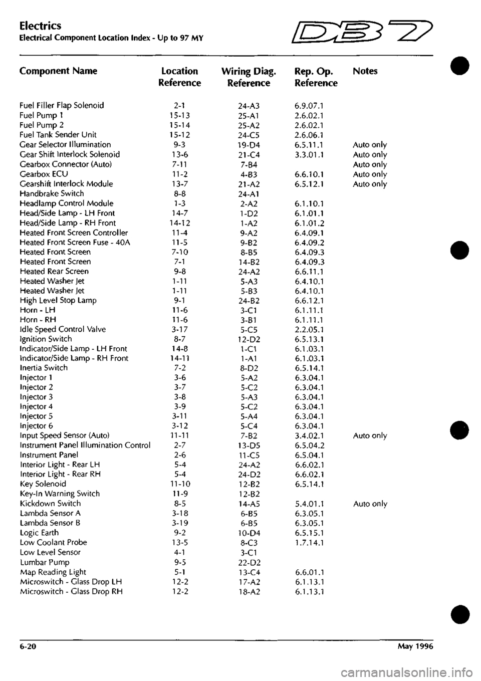
Electrics
Electrical Component Location Index •
Component Name
Fuel Filler Flap Solenoid
Fuel Pump 1
Fuel Pump 2
Fuel Tank Sender Unit
Gear Selector Illumination
Gear Shift Interlock Solenoid
Gearbox Connector (Auto)
Gearbox ECU
Gearshift Interlock Module
Handbrake Switch
Headlamp Control Module
Head/Side Lamp - LH Front
Head/Side Lamp - RH Front
Heated Front Screen Controller
Heated Front Screen Fuse - 40A
Heated Front Screen
Heated Front Screen
Heated Rear Screen
Heated Washer Jet
Heated Washer Jet
High Level Stop Lamp
Horn - LH
Horn - RH
Idle Speed Control Valve
Ignition Switch
Indicator/Side Lamp - LH Front
Indicator/Side Lamp - RH Front
Inertia Switch
Injector 1
Injector 2
Injector 3
Injector 4
Injector 5
Injector 6
Input Speed Sensor (Auto)
Instrument Panel Illumination Control
Instrument Panel
Interior Light - Rear LH
Interior Light - Rear RH
Key Solenoid
Key-In Warning Switch
Kickdown Switch
Lambda Sensor A
Lambda Sensor B
Logic Earth
Low Coolant Probe
Low Level Sensor
Lumbar Pump
Map Reading Light
Microswitch - Glass Drop LH
Microswitch - Glass Drop RH
Up to 97 MY
Location
Reference
2-1
15-13
15-14
15-12
9-3
13-6
7-11
11-2
13-7
8-8
1-3
14-7
14-12
11-4
11-5
7-10
7-1
9-8
1-11
1-11
9-1
11-6
11-6
3-17
8-7
14-8
14-11
7-2
3-6
3-7
3-8
3-9
3-n
3-12
11-11
2-7
2-6
5-4
5-4
11-10
11-9
8-5
3-18
3-19
9-2
13-5
4-1
9-5
5-1
12-2
12-2
Wiring Diag.
Reference
24-A3
25-A1
25-A2
24-C5
19-D4
21-C4
7-B4
4-B3
21-A2
24-A1
2-A2
1-D2
1-A2
9-A2
9-B2
8-B5
14-B2
24-A2
5-A3
5-B3
24-B2
3-C1
3-81
5-C5
12-D2
1-C1
1-A1
8-D2
5-A2
5-C2
5-A3
5-C2
5-A4
5-C4
7-B2
13-D5
11-C5
24-A2
24-D2
12-B2
12-B2
14-A5
6-B5
6-B5
10-D4
8-C3
3-C1
22-D2
13-C4
17-A2
18-A2
Ini^'
IL-^^'^
Rep.
Op.
Reference
6.9.07.1
2.6.02.1
2.6.02.1
2.6.06.1
6.5.11.1
3.3.01.1
6.6.10.1
6.5.12.1
6.1.10.1
6.1.01.1
6.1.01.2
6.4.09.1
6.4.09.2
6.4.09.3
6.4.09.3
6.6.11.1
6.4.10.1
6.4.10.1
6.6.12.1
6.1.11.1
6.1.11.1
2.2.05.1
6.5.13.1
6.1.03.1
6.1.03.1
6.5.14.1
6.3.04.1
6.3.04.1
6.3.04.1
6.3.04.1
6.3.04.1
6.3.04.1
3.4.02.1
6.5.04.2
6.5.04.1
6.6.02.1
6.6.02.1
6.5.14.1
5.4.01.1
6.3.05.1
6.3.05.1
6.5.15.1
1.7.14.1
6.6.01.1
6.1.13.1
6.1.13.1
W3^y
Notes
Auto only
Auto only
Auto only
Auto only
Auto only
Auto only
Auto only
6-20 May 1996
Page 55 of 421
NO COLOUR
PIN
116
NV I
I?
B ?
AREA A6
Si.
H6
COLOUR
fiN
ABEX"
125
N I
B3-23 12?
BY 2 SS_
NO
COLOUR
PIN
100
B I
101
PY ?
AREA B2-20 BI-19
HO
COLOUR
117
B
119
B
120
B
AREA
A2 A2
_«
NO COLOUR
PIN
ASET
103
B I CI
105
Py ' CI
NO COLOUR
PIN
102
B 1
103
B 1
lOfl
PT 2
105
PY 2
Ali^A B2-20
Bl
BI-19
fl
EARTH POINT
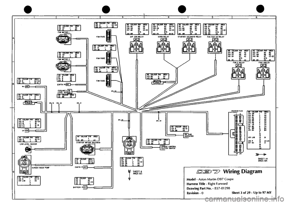
COOLANT
LOW
LEVEL SENSOR
AIR
CON
RELAY
l«
SPl
19
SPL
20
HO COLOUR
PIN
135
NS 65
136
UB 86
137
KB 87
87A
138
RH 3?
AREA
C6 C6
C3-22
..»,
.
NO COLOUR
PIH
133
P 85
140
PB 86
141
P 87
87A
14?
PY 30
AREA C4-24 ce C4-24
.BLI9..
NO COLOUR
PIH
115
N 85
143
BC 86
144
WY 87
S7A 110
WR 30
AREA 02 B4 C6
C2
NO COLOUR
PIK
146
RY 85
120
8 86
147 KB
87
129
UR 87A
130 BG
30
ARCA
A6 B2 C3-22 03 03 STARTER SOLENOID RELAY FAN
RUN ON
RELAY
NO COLOUR AREA 121
WR £5_
HO COLOUR 124
NG
146
RY
126
BY
116
NY
PIN 85 86 8/ 87A
55
AREA
A2 A5 A2
A2
NO COLOUR
PIH
123
NY 85
127
UN 86
148
KB 87
87A
lie
HY 30
AREA
B2 D3
C3-22
.^2...
l/
NO COLOUR
PIN
106
B I
W-S&
2_
AREA 82-21 C6 LOW LEVEL SENSOR
NO COLOUR PIN
ARET
I 110
WR 2 «4
STARTER MOTOR SOLENOID
NO COLOUR III
B
112
e
AREA B2-2I 82-20
SCREEN WASH PUMP
NO COLOUR
PIN
lOe
B 1
109
LCB 2
3 4
AR^A B2-2I C6 NO 113 114 l|^
COLOUR N N H
AlttA A2 B3-23
M
BATTERY
POSTL
NO COLOUR
133
B
134
aw
AREA B2-2I
J
RH
SIDE n REPEATER
NO COLOUR
PIN
131
YR I
132
BK 2
AREA ce C6 J CRUISE CONTROL ^ CLUTCH SWITCH
c
D:
r
ID ID
i D)
IDczt
mm
ffl
m
m m
ID Ul
ii=ir
i m
m ID
Trff'TsrawPir
134
OW
144
WY
135
NS
136
UB
138
RN
140
PB
IJI
YR
132
BK
121
WR
145
BC
109
LCB
149
P
107
BS
1 2 3 4 5 6 7 8 9
10
II 12 13 14 15 16 17 18 19
_.29
AREA
C4 A4 A3 A3 A5 A4 C4 C4 62 B4
01
C4-24
CI
NO COLOUR
PIN
127
UN 1
128
KB 2
129
UR 3
130
Bf. 4
AREA
AS
C3-22
A5
«5
SHEET
14
AREA
B4
SHEET
6
AREA
B3
^27
Wiring Diagram
Model
-
Aston Martin DB7 Coupe
Harness
Title
-
Right Forward
Drawing
Part No.
-
B37-81298
Revision
- 0
Siieet
3 of
29
-
Up
to 97 MY
Page 108 of 421
^7
Electrics
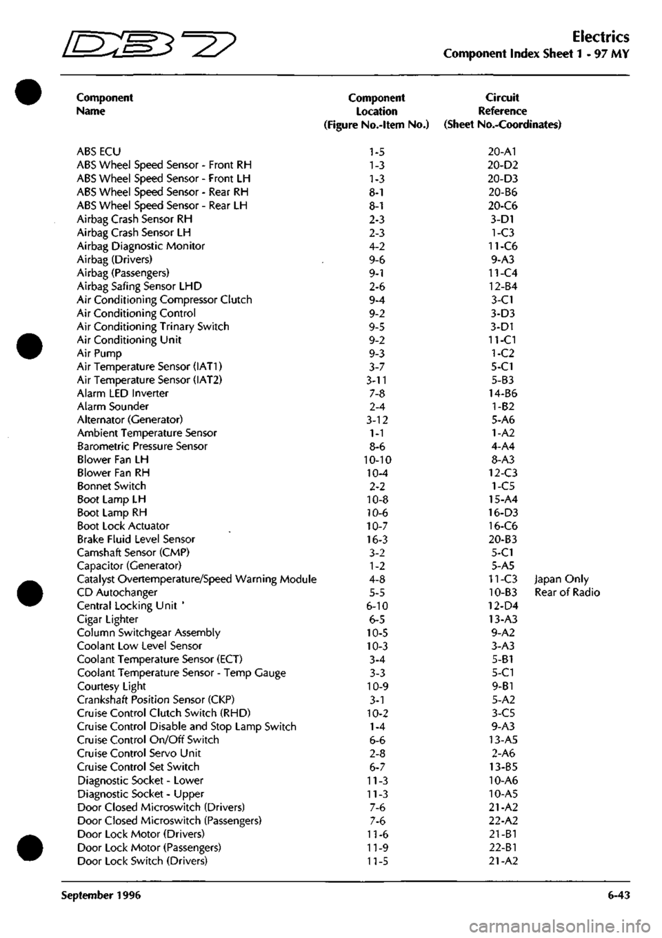
Component Index Sheet 1-97 MY
Component
Name
ABS ECU
ABS Wheel Speed Sensor - Front RH
ABS Wheel Speed Sensor - Front LH
ABS Wheel Speed Sensor - Rear RH
ABS Wheel Speed Sensor - Rear LH
Airbag Crash Sensor RH
Airbag Crash Sensor LH
Airbag Diagnostic Monitor
Airbag (Drivers)
Airbag (Passengers)
Airbag Safing Sensor LHD
Air Conditioning Compressor Clutch
Air Conditioning Control
Air Conditioning Trinary Switch
Air Conditioning Unit
Air Pump
Air Temperature Sensor (IAT1)
Air Temperature Sensor (IAT2)
Alarm LED Inverter
Alarm Sounder
Alternator (Generator)
Ambient Temperature Sensor
Barometric Pressure Sensor
Blower Fan LH
Blower Fan RH
Bonnet Switch
Boot Lamp LH
Boot Lamp RH
Boot Lock Actuator
Brake Fluid Level Sensor
Camshaft Sensor (CMP)
Capacitor (Generator)
Catalyst Overtemperature/Speed Warning Module
CD Autochanger
Central Locking Unit '
Cigar Lighter
Column Switchgear Assembly
Coolant Low Level Sensor
Coolant Temperature Sensor (ECT)
Coolant Temperature Sensor - Temp Gauge
Courtesy Light
Crankshaft Position Sensor (CKP)
Cruise Control Clutch Switch (RHD)
Cruise Control Disable and Stop Lamp Switch
Cruise Control On/Off Switch
Cruise Control Servo Unit
Cruise Control Set Switch
Diagnostic Socket - Lower
Diagnostic Socket - Upper
Door Closed Microswitch (Drivers)
Door Closed Microswitch (Passengers)
Door Lock Motor (Drivers)
Door Lock Motor (Passengers)
Door Lock Switch (Drivers)
Component
Location
(Figure No.-ltem No.)
1-5
1-3
1-3
8-1
8-1
2-3
2-3
4-2
9-6
9-1
2-6
9-4
9-2
9-5
9-2
9-3
3-7
3-11
7-8
2-4
3-12
1-1
8-6
10-10
10-4
2-2
10-8
10-6
10-7
16-3
3-2
1-2
4-8
5-5
6-10
6-5
10-5
10-3
3-4
3-3
10-9
3-1
10-2
1-4
6-6
2-8
6-7
11-3
11-3
7-6
7-6
11-6
11-9
11-5
Circuit
Reference
(Sheet No.-Coordinates)
20-A1
20-D2
20-D3
20-B6
20-C6
3-D1
1-C3
11-C6
9-A3
11-C4
12-B4
3-C1
3-D3
3-D1
11-CI
1-C2
5-C1
5-B3
14-B6
1-B2
5-A6
1-A2
4-A4
8-A3
12-C3
1-C5
15-A4
16-D3
16-C6
20-B3
5-C1
5-A5
11-C3 Japan Only
10-B3 Rear of Radio
12-D4
13-A3
9-A2
3-A3
5-B1
5-C1
9-B1
5-A2
3-C5
9-A3
13-A5
2-A6
13-B5
10-A6
10-A5
21-A2
22-A2
21-B1
22-Bl
21-A2
September 1996 6-43
Page 110 of 421
Electrics
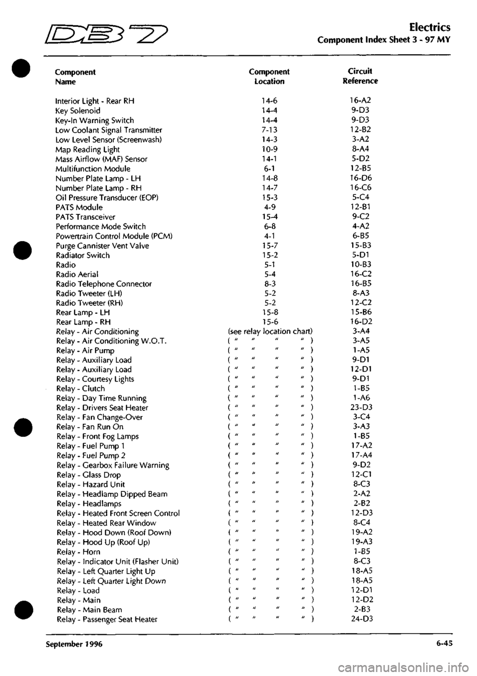
Component Index Sheet 3 - 97
MY
Component
Name
Interior Light - Rear RH
Key Solenoid
Key-In Warning Switch
Low Coolant Signal Transmitter
Low Level Sensor (Screenwash)
Map Reading Light
Mass Airflow (MAF) Sensor
Multifunction Module
Number Plate Lamp - LH
Number Plate Lamp - RH
Oil Pressure Transducer (EOP)
PATS Module
PATS Transceiver
Performance Mode Switch
Powertrain Control Module (PCM)
Purge Cannister Vent Valve
Radiator Switch
Radio
Radio Aerial
Radio Telephone Connector
Radio Tweeter (LH)
Radio Tweeter (RH)
Rear Lamp - LH
Rear Lamp - RH
Relay - Air Conditioning
Relay - Air Conditioning W.O.T.
Relay - Air Pump
Relay - Auxiliary Load (
Relay - Auxiliary Load (
Relay - Courtesy Lights (
Relay - Clutch (
Relay-Day Time Running (
Relay - Drivers Seat Heater (
Relay - Fan Change-Over (
Relay - Fan Run On
Relay - Front Fog Lamps
Relay - Fuel Pump 1
Relay - Fuel Pump 2
Relay - Gearbox Failure Warning
Relay - Glass Drop
Relay - Hazard Unit
Relay - Headlamp Dipped Beam
Relay- Headlamps
Relay - Heated Front Screen Control
Relay - Heated Rear Window
Relay - Hood Down (Roof Down)
Relay - Hood Up (Roof Up)
Relay - Horn
Relay - indicator Unit (Flasher Unit)
Relay - Left Quarter Light Up
Relay - Left Quarter Light Down
Relay - Load
Relay- Main
Relay - Main Beam
Relay - Passenger Seat Heater
Component
Location
14-6
14-4
14-4
7-13
14-3
10-9
14-1
6-1
14-8
14-7
15-3
4-9
15-4
6-8
4-1
15-7
15-2
5-1
5-4
8-3
5-2
5-2
15-8
15-6
see relay location chart) di II II II
II II II II
II II II II
11 II II II
II II II II
II II II II
II II II II
II II II II
II II II II
11 II II II
II II II II
II II II II
II II It II
II II II II
11 II II II
II II II II
II II II II
II II II II
II II II II
II It II II
II II II II
11 II II II
II II II II
11 II II II
11 II II II
II II II II
II II II II
II II II II
II II II II
II II II II
Circuit
Reference
16-A2
9-D3
9-D3
12-82
3-A2
8-A4
5-D2
12-B5
16-D6
16-C6
5-C4
12-B1
9-C2
4-A2
6-B5
15-B3
5-D1
10-B3
16-C2
16-B5
8-A3
12-C2
15-B6
16-D2
3-A4
3-A5
1-A5
9-D1
12-D1
9-D1
1-B5
1-A6
23-D3
3-C4
3-A3
) 1-B5
) 17-A2
) 17-A4
9-D2
) 12-C1
) 8-C3
2-A2
) 2-B2
) 12-D3
) 8-C4
) 19-A2
) 19-A3
) 1-85
) 8-C3
) 18-A5
) 18-A5
) 12-D1
) 12-D2
) 2-83
) 24-D3
September 1996 6-45
Page 295 of 421
Air Conditioning
/J=y>f^^^
—p )
System Trouble Shooting
12.
Compressor clutch slipping.
13.
Blower flaps or distribution vents closed or partially seized.
14.
Water valve not closed.
15.
Evaporator sensor detached from evaporator.
Intermittent Cooling
Is the electrical circuit to the compressor clutch consistent?
2.
Is the electrical circuit to the blower motor(s) consistent?
3. Compressor clutch slipping.
4.
Faulty air distribution flap potentiometer or motor.
5. Motorised in-car aspirator or evaporator temperature sensor faulty, causing temperature variations.
6. Blocked or partially restricted evaporator or condenser.
Noisy System
1.
Loose or damaged compressor drive belt.
2.
Loose or damaged compressor mountings.
3. Compressor oil level low, look for evidence of leakage.
4.
Compressor damage caused by low oil level or internal debris.
5. Blower(s) motor(s) noisy.
6. Excessive refrigerant charge, witnessed by vibration and 'thumping' in the high pressure line (may be indicated by
high HIGH & high LOW side pressures).
7. Low refrigerant charge causing 'hissing' at the expansion valve (may be indicated by low HIGH side pressure).
8. Excessive moisture in the system causing expansion valve noise.
Note;
Electrical faults
may
be more rapidly traced using PDU.
Insufficient Heating
1.
Water valve stuck in the closed position.
2.
Motorised in-car aspirator seized.
3. Blend flaps stuck or seized.
4.
Blocked or restricted blower inlet or outlet.
5. Low coolant level.
6. Blower fan speed low.
7. Coolant thermostat faulty or seized open.
8-18 May 1996
Page 384 of 421
^27
The Aston Martin Lagonda Diagnostic System
Users Guide
Engine Diagnostics - 97 MY
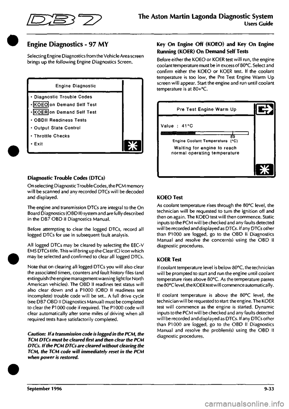
Selecting Engine Diagnostics from the Vehicle Area screen
brings up the following Engine Diagnostics Screen.
Engine Diagnostic
• Diagnostic Trouble Codes
• KOEO on Demand Self Test
• KOER on Demand Self Test
• OBDII Readiness Tests
• Output State Control
• Throttle Checks
• Exit
o
Diagnostic Trouble Codes (DTCs)
On selecting DiagnosticTrouble
Codes,
the PCM memory
will be scanned and any recorded DTCs will be decoded
and displayed.
The engine and transmission DTCs are integral to the On
Board Diagnostics (OBDII) system and are ful ly described
in the DB7 OBD II Diagnostics Manual.
Before attempting to clear the logged DTCs, record all
logged DTCs for use in subsequent fault analysis.
All logged DTCs may be cleared by selecting the EEC-V
EMS DTCs
title.
This will bring up the Clear
(C)
icon which
may be selected and confirmed to clear all logged DTCs.
Note that on clearing all logged DTCs you will also clear
the associated timers, counters and fault history files (and
extinguish the engine management warning lightfor North
American vehicles). The OBD II readines test status will
also clear down and a PI 000 (OBD II readiness test
incomplete) trouble code will be set.. A full drive cycle
(see DB7 OBD II Diagnostics Manual) must be completed
to clear the PI 000 code if required. The PI 000 code will
clear automatically after some miles of driving when all
required tests have satisfactorily completed.
Caution: If a transmission code is logged in the PCM, the
TCM DTCs must be cleared first and then clear the PCM
DTCs. If the PCM DTCs are cleared without clearing the
TCM, the TCM code will immediately reset in the PCM
when power is restored.
Key On Engine Off (KOEO) and Key On Engine
Running (KOER) On Demand Self Tests
Before either the KOEO or KOER test will run, the engine
coolant temperature must be in excess of
BO'C.
Select and
confirm either the KOEO or KOER test. If the coolant
temperature is too low, the Pre Test Engine Warm Up
screen will appear. Start the engine and run until coolant
temperature is at 80+°C.
Pre Test Engine Warm Up
Value : 41°C
80 Engine Coolant Temperature {°C)
Waiting for engine to reach
normal operating temperature
o
KOEO Test
As coolant temperature rises through the BO'C level, the
technician will be requested to turn the ignition off and
then on again. The KOEO test will then commence. Static
inputs to the PCM will be checked and any faults detected
will be recorded and displayed as DTCs. If any DTCs other
than PI 000 are logged, go to the OBD II Diagnostics
Manual and resolve the concern(s) using the OBD 11
diagnostic procedures.
KOER Test
If coolant temperature level is below 80°C, the technician
will be prompted to start and run the engine until coolant
temperature rises above 80°C. As the temperature passes
the 80°C
level,
the KOERtest will commence automatically.
If coolant temperature is above the 80°C level, the
technician wi
11
be requested to start the engine. The KOER
test will commence as the engine is started. Dynamic
inputs to the PCM will be checked and any faults detected
will be recorded and displayed as DTCs. If any DTCs other
than PI 000 are logged, go to the OBD 11 Diagnostics
Manual and resolve the problem(s) using the OBD II
diagnostic procedures.
September 1996 9-33
Page 410 of 421
^^?
The Aston Martin Lagonda Diagnostic System
Users Guide
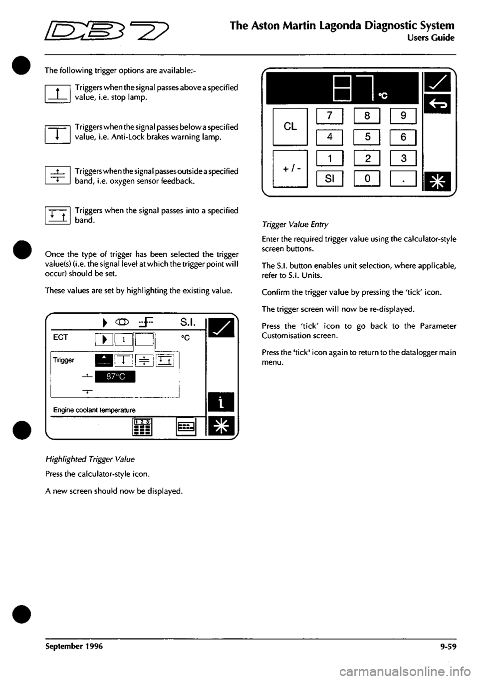
The following trigger options are available:
Triggers when the signal passes above
a
specified
value,
i.e. stop lamp.
Triggers when the signal passes below
a
specified
value,
i.e. Anti-Lock brakes warning lamp.
Triggers when the signa
I
passes outside
a
specified
band,
i.e. oxygen sensor feedback.
Triggers when the signal passes into a specified
band.
Once the type of trigger has been selected the trigger
vaiue(s) (i.e. the signal level at which the trigger point wil
I
occur) should be set.
These values are set by highlighting the existing value.
i
ECT ^ 1
Trigger KBIT" ^
^^^^1
S.I.
°c
Oj
Engine coolant temperature
m
^
Highlighted Trigger Value
Press the calculator-style
icon.
A new screen should now be displayed.
Trigger Value Entry
Enter the required trigger value using the calculator-style
screen buttons.
The S.I. button enables unit selection, where applicable,
refer to S.I. Units.
Confirm the trigger value by pressing the 'tick'
icon.
The trigger screen will now be re-displayed.
Press the 'tick' icon to go back to the Parameter
Customisation screen.
Press the 'tick' icon again to return to the datalogger main
menu.
September 1996 9-59