remove seats ASTON MARTIN DB7 1997 Workshop Manual
[x] Cancel search | Manufacturer: ASTON MARTIN, Model Year: 1997, Model line: DB7, Model: ASTON MARTIN DB7 1997Pages: 421, PDF Size: 9.31 MB
Page 227 of 421
3-^?
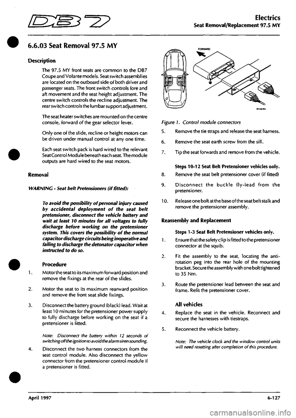
Electrics
Seat Removal/Replacement 97.5 MY
6.6.03
Seat Removal 97.5 MY
Description
The 97.5 MY front seats are common to the DB7
Coupe
and
Volante
models.
Seat
switch
assembi ies
are located on the outboard side of both driver and
passenger
seats.
The front switch controls fore and
aft movement and the seat height adjustment. The
centre switch controls the recline adjustment. The
rear switch
controls
the
lumbar support adjustment.
The seat
heater switches are mounted on the centre
console, forward of the gear selector
lever.
Only one of
the
slide,
recline or height motors can
be driven under manual control at any one time.
Each seat switch pack is hard wired to the relevant
Seat Control
Module
beneath each
seat.
The
module
outputs are hard wired to the seat motors.
Removal
WARNING -
Seat
belt
Pretensioners
(if fitted):
To avoid the possibility
of
personal
injury
caused
by accidental deployment of the seat belt
pretensioner,
disconnect
the
vehicle battery and
wait at
least
10
minutes
for all
voltages
to fully
discharge
before working on the
pretensioner
system.
This covers the possibility
of
the normal
capacitor
discharge
circuits being inoperative and
failing to discharge the detonator capacitor when
instructed
to
do
so.
Procedure
1.
Motortheseatto
its
maximum forward position and
remove the fixings at the rear of the slides.
2.
Motor the seat to its maximum rearward position
and remove the front seat slide fixings.
3. Disconnect the battery
ground
(black)
lead.
Wait at
least 10 minutes for the pretensioner power supply
to fully discharge before working on the seat if a
pretensioner is fitted.
Note: Disconnect the battery within 12 seconds of
switching off the ignition to avoid the alarm siren sounding.
4.
Disconnect the two harness connectors from the
seat control module. Also disconnect the yellow
connector from the pretensioner control module if
a pretensioner is fitted.
Figure 1. Control module connectors
5. Remove the tie straps and release the seat harness.
6. Remove the seat earth screw from the
sill.
7. Tip the seat forwards and remove from the vehicle.
Steps 10-12 Seat Belt Pretensioner vehicles only.
8. Remove the seat belt pretensioner cover (if fitted)
9. Disconnect the buckle fly-lead from the
pretensioner.
10.
Release
one
bolt at
the
base of the
seat
belt stalk and
remove the pretensioner assembly.
Reassembly and Replacement
Steps 1-3 Seat Belt Pretensioner vehicles only.
1.
Ensurethatthesafetyclipisfittedtothepretensioner
connector at the squib.
2.
Fit the assembly to the seat, locating the
anti-
rotation peg into the rear hole of the mounting
bracket.
Securethe
assembly with
one
bolttightened
to 35 Nm.
3. Route the pretensioner lead between the seat and
frame.
Refit the pretensioner
cover.
All vehicles
4.
Replace the seat in the vehicle. Reconnect and
secure the harnesses with tiestraps.
5. Reconnect the vehicle battery.
Note:
The vehicle clock and the window control units
will
need resetting after completion
of
this
procedure.
April 1997 6-127
Page 229 of 421
O" D^?
Body and Trim
Contents
Contents
Body and Trim
Body Repair
Potential Risks
Precautions
General Repair Notes
Steel Body Parts - Repair, Remove and Replace
RTM Body Parts
Body Panel and Trim Removal
Front Apron
Front Undertray
Wheel Arch Liners
Side Sills (top fixings)
Side Sills (bottom fixings)
Rear Bumper
Doors
Door Liners
Door Liner (components)
Steering Wheel
Column Switches
Instrument Panel (surround)
Instrument Panel
Facia Underscuttles
Glove Box
Facia Mountings (1)
Facia Mountings (2)
Console Instruments
Radio
Front Seats
Ashtray
Centre Console
Seat ECU Covers
Rear Console
Rear Seats and C Post Trim
Quarter Panels, B Post Panels, Parcel Shelf
Headlining
Roof System Description and Repair Procedures
Vol ante Roof
Roof and Rear Quarter Light Control
Roof Component Location
Roof Control System
9.0.02.1
Roof Removal/Replacement
9.0.02.3
Roof Hydrailic Control System
9.0.02.5
Bleeding the Roof Hydraulic System
9.1.01.1
Rear Quarter Window Renewal
9.1.01.2
Rear Quarter Glass Adjustment
9.1.01.4
Rear Quarter Window Lift Motor - LH
9.1.01.5
Rear Quarter Window Lift Motor - RH
Roof Sealing and Wind Noise
9.2.01.5
'A' Post/Header Sealing and Lock Adj
9.2.01.6
Roof Seals - Adjustment
9.2.01.7
Cheater Plate Seals - Adjust/Renew
9.2.01.8
Door Glass Adjustment
Alcantara Cleaning
7-1
7-2
7-2
7-3
7-3
7-4
7-5
7-6
Sheet 1
Sheet 2
Sheet 3
Sheet 4
Sheet 5
Sheet 6
Sheet 7
Sheet 8
Sheet 9
Sheet 10
Sheet 11
Sheet 12
Sheet 13
Sheet 14
Sheet 15
Sheet 16
Sheet 17
Sheet 18
Sheet 19
Sheet 20
Sheet 21
Sheet 22
Sheet 23
Sheet 24
Sheet 25
Sheet 26
Sheet 27
7-7
7-7
7-8
7-9
7-10
7-11
7-12
7-13
7-14
7-15
7-16
7-17
7-17
7-18
7-19
7-20
7-21
May 1996 7-1
Page 234 of 421
Body and Trim
Body Panel and Trim Removal 5^7
Body Panel and Trim Removal
The following diagrams show the fixings for all
removeable body and trim panels.
Sheet 1. Front Apron
Sheet 2. Front Undertray
Sheet 3. Wheel Arch Liners
Sheet 4. Side Sills (top fixings)
Sheets. Side Sills (bottom fixings)
Sheet 6. Rear Bumper
Sheet 7. Doors
Sheet 8. Door Liners
Sheet 9. Door Liner (components)
Sheet 10. Steering Wheel
Sheet 11. Column Switches
Sheet 12. Instrument Panel (surround)
Sheet 13. Instrument Panel
Sheet 14. Facia Underscuttles
Sheet 15. Glove Box
Sheet 16. Facia Mountings (1)
Sheet
1
7. Facia Mountings (2)
Sheet 18. Console Instruments
Sheet 19. Radio
Sheet 20. Front Seats
Sheet
21.
Ashtray
Sheet 22. Centre Console
Sheet 23. Seat ECU Covers
Sheet 24. Rear Console
Sheet 25. Rear Seats and C Post Trim
Sheet 26. Quarter Panels, B Post Panels, Parcel Shelf
Sheet 27. Headlining
7-6 May 1996
Page 265 of 421
Body and Trim
Roof Removal/Replacement [D::M^=2?
9.0.02.1 - Roof Removal/Replacement
1.
2.
3.
4.
5.
6.
7.
8.
Move the front seats fully forward for access.
Remove the rear seat squab and cushion. Remove
the rear quarter trim panel.
Release the roof side curtain clips.
Release the rear window support bracket securing
bolts (Fig 1-2).
Remove the side curtain clips (2 per side).
Release the side curtain rods and move the curtains
aside.
Disconnect the heated rear window connector.
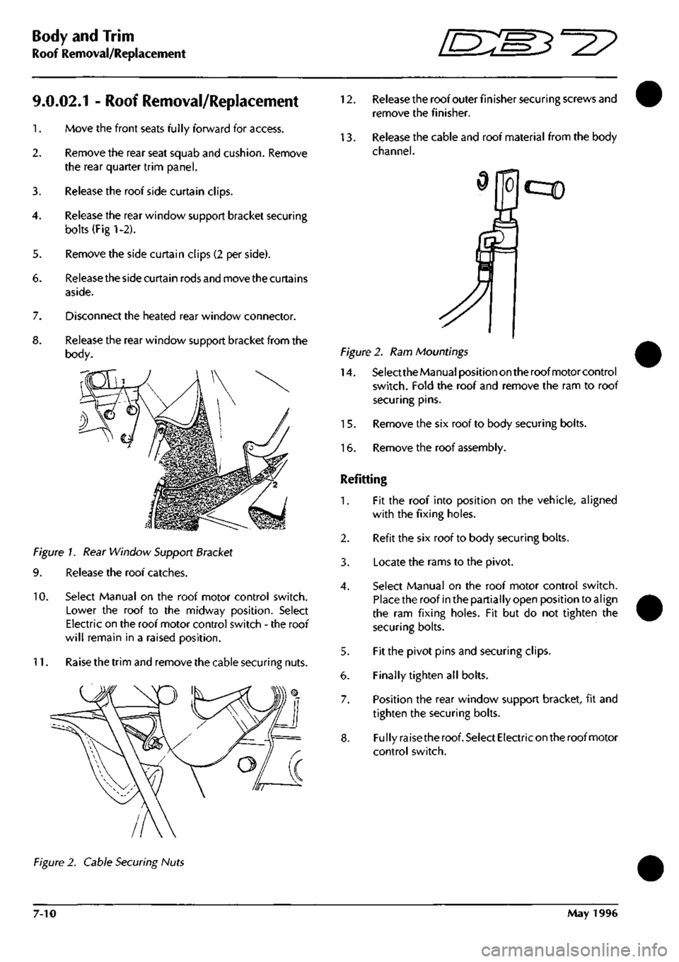
Release the rear window support bracket from the
body.
Figure 1. Rear Window Support Bracket
9. Release the roof catches.
10.
Select Manual on the roof motor control switch.
Lower the roof to the midway position. Select
Electric on the roof motor control switch - the roof
will remain in a raised position.
11.
Raise the trim and remove the cable securing nuts.
12.
Release the roof outer finisher securing screws and
remove the finisher.
13.
Release the cable and roof material from the body
channel.
cqD
Figure 2. Ram Mountings
14.
Select the Manual position on the roof motor control
switch.
Fold the roof and remove the ram to roof
securing pins.
15.
Remove the six roof to body securing bolts.
16.
Remove the roof assembly.
Refitting
1.
Fit the roof into position on the vehicle, aligned
with the fixing holes.
2.
Refit the six roof to body securing bolts.
3. Locate the rams to the pivot.
4.
Select Manual on the roof motor control switch.
Place the roof in the partially open position to
al
ign
the ram fixing holes. Fit but do not tighten the
securing bolts.
5. Fit the pivot pins and securing clips.
6. Finally tighten all bolts.
7. Position the rear window support bracket, fit and
tighten the securing bolts.
8. Fully raise the roof. Select Electric on the roof motor
control switch.
Figure 2. Cable Securing Nuts
7-10 May 1996
Page 266 of 421
^=2?
Body and Trim
Roof Hydraulic Control System
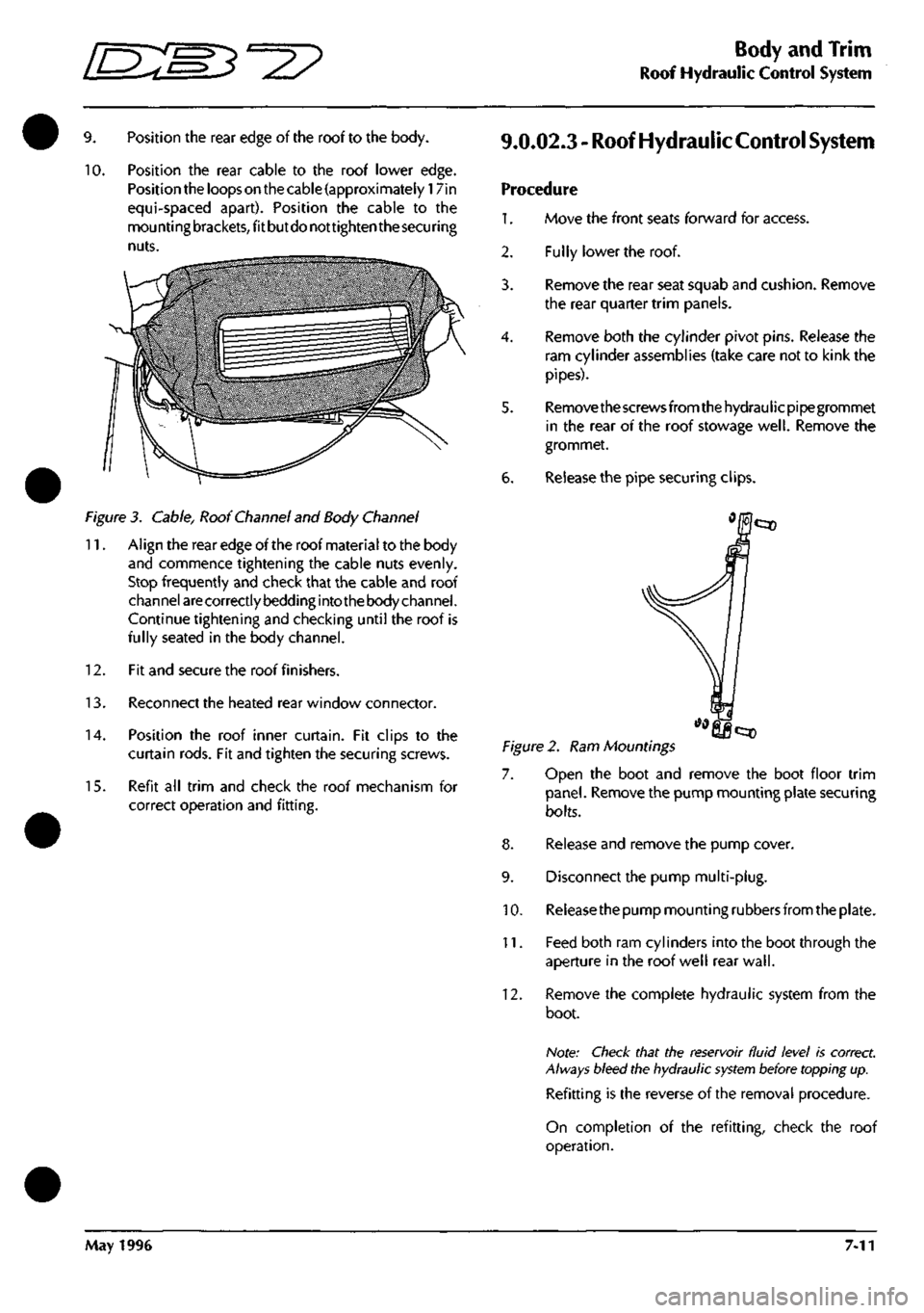
9. Position the rear edge of the roof to the body.
10.
Position the rear cable to the roof lower edge.
Position the loops on the cable (approximately 17in
equi-spaced apart). Position the cable to the
mou nti ng
brackets,
fit but do not tighten the
secu
ring
nuts.
Figure 3. Cable, Roof Channel and Body Channel
11.
Align the rear edge of the roof material to the body
and commence tightening the cable nuts evenly.
Stop frequently and check that the cable and roof
channel
are
correctly bedding into the body channel.
Continue tightening and checking until the roof is
fully seated in the body channel.
12.
Fit and secure the roof finishers.
13.
Reconnect the heated rear window connector.
14.
Position the roof inner curtain. Fit clips to the
curtain rods. Fit and tighten the securing screws.
15.
Refit all trim and check the roof mechanism for
correct operation and fitting.
9.0.02.3 - Roof Hydraulic
Control
System
Procedure
1.
Move the front seats forward for access.
Fully lower the roof.
2.
3.
4.
6.
Remove the rear seat squab and cushion. Remove
the rear quarter trim panels.
Remove both the cylinder pivot pins. Release the
ram cylinder assemblies (take care not to kink the
pipes).
Remove the screws from the hydraulicpipegrommet
in the rear of the roof stowage
well.
Remove the
grommet.
Release the pipe securing clips.
Figure 2. Ram Mountings
7. Open the boot and remove the boot floor trim
panel.
Remove the pump mounting plate securing
bolts.
8. Release and remove the pump cover.
9. Disconnect the pump multi-plug.
10.
Releasethe pump mounting rubbers from the plate.
11.
Feed both ram cylinders into the boot through the
aperture in the roof well rear
wall.
12.
Remove the complete hydraulic system from the
boot.
Note: Check that the reservoir fluid level is correct.
Always bleed the hydraulic
system
before topping up.
Refitting is the reverse of the removal procedure.
On completion of the refitting, check the roof
operation.
May 1996 7-11
Page 289 of 421
Air Conditioning //~-->> ^/zz:^^ • ^ ^
General Svstem Procedures ' —"^ ^ '^ General System Procedures
From the condenser the liquid passes into the Receiver-Drier which has three functions:
• Storage vessel for varying system refrigerant demands.
• Filter to remove system contaminants.
• Moisture removal via the desiccant.
With the passage through the receiver-drier completed the, still high pressure liquid refrigerant, enters the Expansion
Valve where it is metered through a controlled orifice which has the effect of reducing the pressure and temperature.
The refrigerant, now in a cold atomised state, flows into the Evaporator and cools the air which is passing through
the matrix.
As heat is absorbed by the refrigerant it once again changes state, into a vapour, and returns to the compressor for
the cycle to be repeated (Fig. 5).
There is an automatic safety valve incorporated in the compressor which operates should the system pressure be
in excess of
41
bar. The valve re-seats when the pressure drops below 35 bar.
Note: The division of HIGH and LOW side is simply the
system pressure
differential created by the
compressor
discharge
(pressure),
suction
(inlet)
ports and
the
relative inlet and outlet
ports
of the
expansion
valve.
This
differential is critical to
system
fault
diagnosis
and efficiency checks.
System Protection
The trinary pressure switch, located in the liquid line, cuts electrical power to the compressor clutch if the system
pressure is outside of the range of 2 Bar
(1
st Function) to 27 Bar (2nd Function). The third function is to switch on
the cooling fans when pressure exceeds 20 bar.
General System Procedures
Leak Test
Faults associated with low refrigerant charge weight and low pressure may be caused by leakage. Leaks traced to
mechanical connections may be caused by torque relaxation or joint face contamination. Evidence of oil around
such areas is an indicator of leakage. When checking for non visible leaks use only a dedicated Refrigerant El 34A
electronic analyser and apply the probe all round the joint connection. Should a leak be traced to a joint, check that
the fixing is secured to the correct tightening torque before any other action is taken.
Do not forget to check the compressor shaft seal and evaporator.
Note: Never
use
a dedicated
CFC 12
or
naiced
flame type
analyser.
Charge Recovery (System Depressurisation)
The process of refrigerant recovery depends on the basic characteristics of your chosen recovery-recycle-recharge
equipment, therefore, follow the manufacturers instructions carefully. Remember that compressor oil may be drawn
out of the system by this process, take note of the quantity recovered so that it may be replaced.
CAUTION: Observe all relevant safety requirements.
• Do not vent refrigerant directly to atmosphere and always use approved recovery-recycle-recharge
equipment.
• Wear suitable eye and skin protection.
• Do not mix the refrigerant with CFC 12.
• Take note of the amount of recovered refrigerant, it indica
tes the
state of the
system
and
thus the
magnitude
of any problem.
8-12 May 1996
Page 332 of 421
^2?
Air Conditioning Repair Procedures
Hose - Compressor to Evaporator/Air-Con Unit Renew
8.1.06.1 Hose-Compressor
to
Evaporator
Renewal
Procedure
1.
Open the bonnet and fit a wing cover.
2.
Depressurise the air conditioning systenn.
3. Remove the hose to evaporator valve clamping
plate,
disconnect the hose from the valve, remove
and discard the 'O' ring
seal.
4.
Fit a blanking plug to the evaporator valve. Release
the evaporator hose securing clips.
5. Remove the compressor outlet port retaining bolt.
6. Disconnect the hose from the compressor, discard
the hose complete with 'O' ring seals.
7. Connect the hose to the evaporator valve and
tighten clamp onto the hose.
8. Route the hose to the compressor, fit a new 'O' ring
seal and connect it to the compressor.
9. Position the outlet port retaining plate on the
compressor, fit and tighten the securing bolt.
10.
Refit the hose to the clips.
11.
Charge the air conditioning system.
12.
Remove the wing cover and close the bonnet.
8.2.01.1 Air Conditioning Unit Renewal
1.
Disconnect the battery earth
lead.
2.
Drain the engine coolant into a suitable container.
3. Depressurise the air conditioning system.
4.
Disconnect the high and low pressure hoses and
expansion valve from the air conditioning unit (see
expansion valve renewal).
5. Slacken the coolant hose to the heater matrix pipe
securing clips and disconnect the hoses from the
matrix. (This will require the removal of the air
intake hose for access.)
6. Remove the following items from inside the car:
front seats
underscuttle panels/knee bolsters
glove box assembly
facia trim (walnut trim)
radio and ashtray
centre console switch panel assembly
instrument panel and surround trim
steering wheel and column
facia assembly complete
hoses - distribution box to door vents
facia support frame
Details and drawings of the above operations can
be found in the electrical and trim sections.
Disconnect the vacuum hoses from the blower
motors, water valve and reservoir.
Un-clip the electrical harness from the air
conditioningunit, release theelectrical connections
and reposition the harness to allow removal of the
unit.
Displace and remove the footwell ventilator ducts
and hoses (Fig. 1-1).
May 1996 8-55