power steering ASTON MARTIN V8 VANTAGE 2010 Workshop Manual
[x] Cancel search | Manufacturer: ASTON MARTIN, Model Year: 2010, Model line: V8 VANTAGE, Model: ASTON MARTIN V8 VANTAGE 2010Pages: 947, PDF Size: 43.21 MB
Page 3 of 947
Contents
Issue 5, January 2010 Workshop Manual 0-0-3
V8 Vantage Workshop Manual
Contents
IntroductionWelcome .............................................................. 0-0-6
Safety Precautions ................................................. 0-0-7
Lifting and Jacking ................................................. 0-0-9
Vehicle Recovery ................................................ 0-0-10
Vehicle Identification Number ............................ 0-0-11
Body System (01.00) Body Structure (01.01) .......................................... 1-1-4
Front End System (01.02) ...................................... 1-2-1
Body Closures (01.03) ........................................... 1-3-1
Interior Trim (01.05) ............................................. 1-4-1
Exterior Trim (01.08) ............................................. 1-8-1
Mirrors (01.09) ...................................................... 1-9-1
Seating (01.10).................................................... 1-10-1
Glass, Frame and Mechanism (01.11) .................. 1-11-1
Instrument Panel (IP) (01.12) . .............................. 1-12-1
Handles and Lock Mechanisms (01.14) ............... 1-14-1
Wipers and Washer System (01.16)..................... 1-16-1
Convertible Roof and Roof Opening
Subsystem (01.17)................ ...............................1-17-1
Bumpers (01.19) ................................................. 1-19-1
Restraining Devices (01.20) .... ............................. 1-20-1
Frame and Mounting (02.00) Subframes (02.03) ................................................. 2-1-2
Engine System (03.00) Engine Assembly....................................................3-0-3
Engine Structure (03.01)........................................ 3-1-1
Lubrication System (03.02).................................... 3-2-1
Cooling System (03.03) ......................................... 3-3-1
Fuel Charging System (03.04) ................................ 3-4-1
Accessory Drive System (03.05)............................. 3-5-1
Engine Cranking System (03. 06) ............................ 3-6-1
Valve Train (03.09) ............................................... 3-9-1
Engine Sealing (03.10)......................................... 3-10-1
Power Conversion (03.11)................................... 3-11-1
Evaporative Emissions (03.13) ............................. 3-11-1
Engine Management System (0 3.14).................... 3-14-1
Throttle Control (03.16) ...... ................................ 3-16-1
Foot Operated Control (03.18)............................ 3-18-1
Suspension (04.00) Road Wheel Alignment (04.00) ............................. 4-0-2
Front Suspension (04.01)....................................... 4-1-1
Rear Suspension (04.02)........................................ 4-2-1
Shock Absorber System (04.03) ............................. 4-3-1
Road Wheels and Tyres (04.04) ............................ 4-4-1
Driveline (05.00) Driveshaft (05.01) ................................................. 5-1-2
Halfshafts (05.05) .................................................. 5-2-1 Brake System (06.00)
Front Disc Brake (06.03) ....................................... 6-3-2
Rear Disc Brakes (06.04) ....................................... 6-4-1
Hand Brake (06.05) .............................................. 6-5-1
Brake Actuation System (06.06 ) ............................ 6-6-1
Power Brake System (06.07) ................................. 6-7-1
Anti-lock Braking System (06.09)........................... 6-9-1
Transmission (07.00) Transmission Cooling (07.02) ................................ 7-0-2
Manual Transmission (07.03) ................................ 7-3-1
Automatic Control System (07.05)......................... 7-5-1
Manual Control System (07.06) ............................. 7-6-1
Automatic Shifting Subsytem (07.11) .................. 7-11-1
Clutch (08.00) Clutch Controls (08.02) ......................................... 8-1-2
Exhaust (09.00) Exhaust Overview ................................................. 9-1-2
Silencer Assembly (09.01) ..................................... 9-1-3
Pipes and Supports (09.03) ................................... 9-2-1
Exhaust Protection (09.04) .................................... 9-3-1
Fuel (10.00) Fuel Tank and Lines (10.01) ................................ 10-1-2
Steering (11.00) Steering Gear (11.01) .......................................... 11-1-2
Power Steering (11.02)........................................ 11-2-1
Steering Column (11.04) ..................................... 11-4-1
Steering Column Switches (1 1.05) ....................... 11-5-1
Steering Wheel (11.06) ....................................... 11-6-1
Climate Control (12.00) Body Ventilation system (12.01) .......................... 12-1-2
Heater System (12.02) ........................................ 12-2-1
Air Conditioning (A/C) System (12.03) ................. 12-3-1
Information, Gauge and Warning (13.00) Instrument Cluster (13.01) .................................. 13-1-2
Power Supply (14.00) Battery System (14.01) ........................................ 14-1-2
Alternator and Regulator System (14.02) ............. 14-2-1
Vehicle Entertainment (15.00) Audio System (15.01)................................ ..........15-1-2
Antenna (15.02).................................................. 15-2-1
Vacuum Distribution (16.00) Body Vacuum System (16.01) ............................. 16-1-2
Lighting (17.00) Front Lights (17.01) ............................................. 17-1-2
Interior Lighting (17.02) ...................................... 17-2-1
Rear Lights (17.03) .............................................. 17-3-1
Lighting Mechanisms (17.04). .............................. 17-4-1
Page 6 of 947
Welcome
0-0-6 Workshop Manual Issue 5, January 2010
Welcome
This Workshop Manual is part of a suite of technical manuals
provided for V8 Vantage. Other technical manuals include:
• Parts manual
• OBDII Diagnostic manual
• Man hour schedules
Chapters
Each chapter in this workshop manual is associated with a 4
digit number, i.e. Transmission (07.00). Each chapter is then
further broken into sections, i.e. Automatic Transmission
(07.01).
Chapter Navigation
Example 1:
Older workshop manuals would have Steering and
Suspension together in one chapter. The structure now used
places Steering and Suspension into their own chapters.
When required references are made out to other chapters.
Page Numbering
The page numbering system used within this workshop
manual is as follows:
Systems Classification Coding
Alongside the ‘System’ and ‘Sub system’ section titles appear
codes. For example Exhaust ‘ 09.00’ or Power Steering
‘ 11.02 ’. These codes relate to a Corporate Product Systems
Classification (CPSC) and are designed to segregate the parts
for engineering release and organise a variety of engineering
data.
Special Tools
Where special service tools are required to perform an
operation, the tool number is recorded at the point of use
within the procedure. Where the operation of a special
service tool is complicated or not obvious, refer to Appendix
and Glossary for detailed operation procedures. A pictorial
list of special service tools available for this vehicle can also
be found in Appendix and Glossary.
Location References
References to left, right, front or rear of the vehicle or of a
component are referenced from sitting in the drivers seat
facing forward. Any such refe rences to assemblies removed
from the vehicle are to the normal orientation of the
assembly when installed in the vehicle.
The following Warnings, Cautions and Notes are used within
this Owner’s Guide to call your attention to specific types of
information.
Warnings, Cautions and Notes
Warnings
Cautions
Notes
Repairs and Replacements
Where replacement parts are required, it is essential that
only genuine Aston Martin parts are used. Your attention is
drawn to the following points concerning repairs and the
fitting of genuine Aston Martin parts and accessories:
• Safety features embodied in the vehicle may be impaired if other than genuine Aston Martin parts are installed. In
certain territories, legislation prohibits the fitting of parts
which are not produced to the manufacturers
specification
• Adhere to torque wrench settings given in this manual
• Locking devices, where specified, must be installed. If the efficiency of a locking device is impaired during removal,
it must be renewed
• The vehicle warranty may be invalidated by the installation of other than genuine Aston Martin parts
3- 2- 5
System, i.e. Engine system
Subsystem, i.e. Engine lubrication system
Page Number, i.e. Number within subsystem
WAR NI NG
IDENTIFIES PROCEDURES WHICH MUST BE
FOLLOWED PRECISELY TO HELP AVOID THE RISK OF PERSONAL INJURY.
Caution
Provided to indicate procedur es which must be followed
precisely to reduce the possibility of damage to the vehicle.
Provided to indicate procedur es which will help to avoid
difficulties in the oper ation of the vehicle.
Page 10 of 947
Vehicle Recovery
0-0-10 Workshop Manual Issue 5, January 2010
Vehicle Recovery
General
Preferred method of vehicle recovery is by flat bed
transporter.
The towing eye is primarily for emergency use when towing
for short distances, e.g. removing vehicle if it is causing an
obstruction or winching vehicl e onto a flatbed transporter.
If moving this vehicle in such a situation, install the towing
eye to the bracket in the lower grille aperture.
Transporting
If vehicle is to be transported on a trailer or flat bed
transporter the handbrake must be applied and the road
wheels must be chocked.
Suspended Towing
Take care when using 'spectacle frame' type towing
equipment that the towing device is well clear of front or
rear apron. Body damage may occur if vehicle passes over
uneven road surfaces.
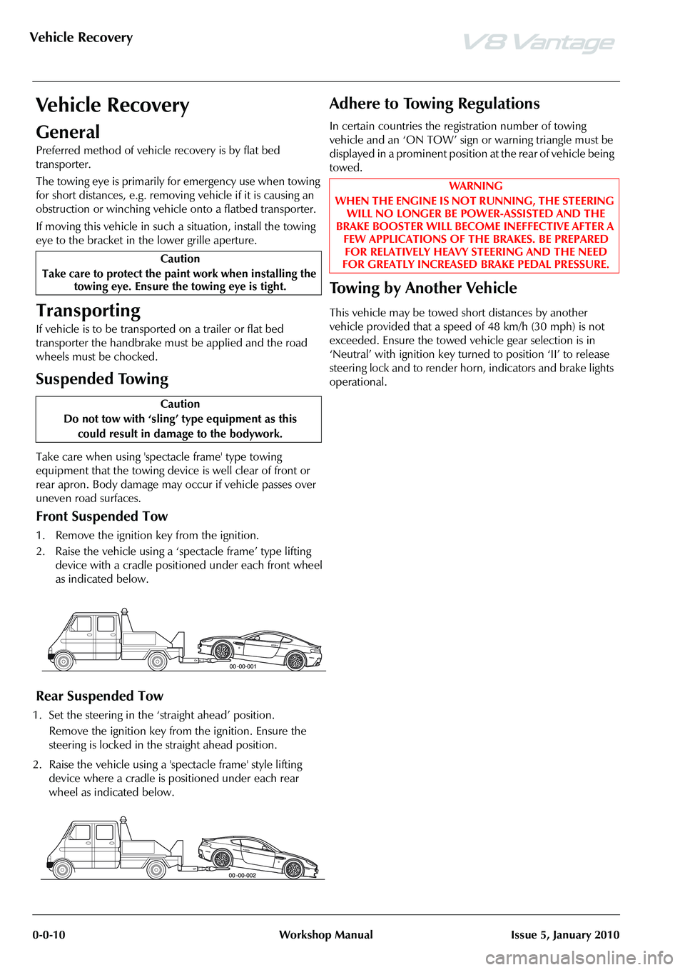
Front Suspended Tow
1. Remove the ignition key from the ignition.
2. Raise the vehicle using a ‘spectacle frame’ type lifting device with a cradle positioned under each front wheel
as indicated below.
Rear Suspended Tow
1. Set the steering in the ‘straight ahead’ position.
Remove the ignition key from the ignition. Ensure the
steering is locked in the straight ahead position.
2. Raise the vehicle using a 'spectacle frame' style lifting device where a cradle is positioned under each rear
wheel as indicated below.
Adhere to Towing Regulations
In certain countries the regi stration number of towing
vehicle and an ‘ON TOW’ sign or warning triangle must be
displayed in a prominent position at the rear of vehicle being
towed.
To w i n g b y A n o t h e r V e h i c l e
This vehicle may be towed short distances by another
vehicle provided that a speed of 48 km/h (30 mph) is not
exceeded. Ensure the towed vehicle gear selection is in
‘Neutral’ with ignition key turned to position ‘II’ to release
steering lock and to render hor n, indicators and brake lights
operational.
Caution
Take care to protect the paint work when installing the towing eye. Ensure the towing eye is tight.
Caution
Do not tow with ‘sling’ type equipment as this
could result in damage to the bodywork.
WAR NI NG
WHEN THE ENGINE IS NOT RUNNING, THE STEERING WILL NO LONGER BE POWER-ASSISTED AND THE
BRAKE BOOSTER WILL BECOME INEFFECTIVE AFTER A FEW APPLICATIONS OF TH E BRAKES. BE PREPARED
FOR RELATIVELY HEAVY STEERING AND THE NEED
FOR GREATLY INCREASED BRAKE PEDAL PRESSURE.
Page 216 of 947
Restraining Devices (01.20)
Body System (01.00)1-14-4 Workshop Manual May 2007
event that does not. The RCM governs the operation of the
whole system and performs continual system diagnostics.
Information on the severity of an impact is received from the
impact sensors.
Variations in the deployment of the front airbag modules are
dependent on the status of the front safety belt buckles.
Dual Inflation Technology
When activated, the airbags will deploy at either a normal or
reduced level of inflation, depending on crash severity.
Various sensors determine the direction and severity of an
impact. The system analyses this information then deploys
the appropriate airbags.
Impact Sensors
Side Impact - Side impact sensors are mounted to the base
of each B-pillar and within each door. In the event of a side
impact, the RCM processes the impact data sent by the side
impact sensor against stored data. The RCM will deploy the
side airbag on the side the deployment request was initiated
and the seat belt pretensioner.
Front Impact - Front impact sensors (x2) are located under
the grill opening panel.
The SRS module processes the impact data sent by the front
impact sensor against stored data, and deploys the front
airbags, and the seat belt pretensioners.
Passenger Airbag Deactivation
The passenger airbag can be deactivated using the PAD
(Passenger Airbag Deactivation) switch. Switching the
passenger airbag off allows children under the age of 12 to
be carried safely in the passenger seat. The PAD switch is
located at the passenger end of the instrument panel and is
accessible when the pa ssenger door is open.
Maintenance
Driver’s Airbag Module - Renew
Removal
1. Disconnect vehicle battery.
2. Allow a two minute power down period to de-activate
airbag system.
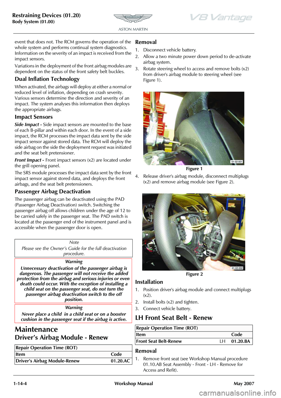
3. Rotate steering wheel to access and remove bolts (x2) from driver's airbag module to steering wheel (see
Figure 1).
4. Release driver's airbag mo dule, disconnect multiplugs
(x2) and remove airbag module (see Figure 2).
Installation
1. Position driver's airbag mo dule and connect multiplugs
(x2).
2. Install bolts (x2) and tighten.
3. Connect vehicle battery.
LH Front Seat Belt - Renew
Removal
1. Remove front seat (see Workshop Manual procedure 01.10.AB Seat Assembly - Front - LH - Remove for
Access and Refit).
Note
Please see the Owner’s Guid e for the full deactivation
procedure.
Warning
Unnecessary deactivation of the passenger airbag is
dangerous. The passenger will not receive the added
protection from the airbag and serious injuries or even
death could occur. With the exception of installing a child seat on the passenge r seat, do not turn the
passenger airbag deactiva tion switch to the off
position.
Warning
Never place a child in a child seat or on a booster
cushion in the passenger seat if the airbag is active.
Repair Operation Time (ROT)
Figure 1
Figure 2
Repair Operation Time (ROT)
ItemCode
Front Seat Belt-Renew LH01.20.BA
Page 285 of 947

Lubrication System (03.02)
Engine (03.00)
Issue 5, Janauary 2010 Workshop Manual 3-2-11
3. Remove pipes from oil tank (refer to Figure 1).
Figure 1
4. Raise vehicle on ramp.
5. Remove undertray (refer to Workshop Manual procedure. 01.02.NB Undertray - Front - Renew).
6. Remove pipe from oil thermostat (position container to catch oil) (refer to Figure 2).
Figure 2
Installation
1. Install pipe to oil thermostat (torque) ensure correct alignment in oil tank bracket.
2. Install undertray (refer to Workshop Manual procedure 01.02.NB Undertray - Front - Renew).
3. Lower vehicle on ramp.
4. Install oil pipe to tank.
5. Install throttle body duct.
6. Connect breather pipe quickf its (x2) to air cleaner duct.
7. Fill tank with approximately amount of displaced oil and replace cap.
8. Use handbook procedure to check oil level.
Oil Pump Inlet Tube Assembly - Renew
Removal
1. Remove the PAS pump (refer to Workshop Manual procedure 03.05.AA Pump - Power Steering - Renew).
2. Remove pipe from oil contro ller (position container to
catch oil).
3. Remove bolt, pipes to bracket (refer to Figure 1).
Figure 1
4. Remove LH exhaust manifo ld (refer to Workshop
Manual procedure 09.00.CD Gasket - Exhaust Manifold
- LH - Renew).
5 . R e m o v e h a r n e s s t o p i p e c l i p ( r e f e r t o F i g u r e 2 ) .
Figure 2
6. Remove bolts that attach the oil pipes to block.
7. Release both pipes from bl ock and remove inlet pipe.
Installation
1. Renew O-ring on remaining oil pipe.
2. Install inlet pipe and position both pipes into block.
A030244
A030246
Repair Operation Time (ROT)
A030248
A030247
Page 286 of 947

Lubrication System (03.02)
Engine (03.00)3-2-12 Workshop Manual Issue 5, Janauary 2010
3. Install bolts that attach th e oil pipes to block (torque).
4. Install LH exhaust manifold (refer to Workshop Manual
procedure 09.00.CD Gasket - Exhaust Manifold - LH -
Renew).
5. Install bolt, pipes to bracket.
6. Install harness clip to pipe.
7. Install pipe to oil controller (torque).
8. Install P.A.S pump (refer to Workshop Manual procedure 03.05.AA Pump - Power Steering - Renew).
9. Fill tank with approximately amount of displaced oil and replace cap.
10. Use handbook procedure to check oil level.
Oil Pump Inlet Tube Assembly - Renew
Removal
1. Remove the PAS pump (refer to Workshop Manual procedure 03.05.AA Pump - Power Steering - Renew).
2. Remove pipe from oil controller (position container to catch oil).
3. Remove bolt, pipes to bracket (refer to Figure 1).
Figure 1
4. Remove LH exhaust manifold (refer to Workshop Manual procedure 09.00.CD Gasket - Exhaust Manifold
- LH - Renew). 5 . R e m o v e h a r n e s s t o p i p e c l i p ( r e f e r t o F i g u r e 2 ) .
Figure 2
6. Remove bolts that attach the oil pipes to block.
7. Release both pipes from bl
ock and remove inlet pipe.
Installation
1. Renew O-ring on remaining oil pipe.
2. Install inlet pipe and position both pipes into block.
3. Install bolts that attach the oil pipes to block (torque).
4. Install LH exhaust manifold (refer to Workshop Manual
procedure 09.00.CD Gasket - Exhaust Manifold - LH -
Renew).
5. Install bolt, pipes to bracket.
6. Install harness clip to pipe.
7. Install pipe to oil controller (torque).
8. Install P.A.S pump (refer to Workshop Manual procedure 03.05.AA Pump - Power Steering - Renew).
9. Fill tank with approximatel y amount of displaced oil and
replace cap.
10. Use handbook procedure to check oil level.
Oil Pump Outlet Tube Assembly - Renew
Removal
1. Remove PAS pump (refer to Workshop Manual procedure 03.05.AA Pump - Power Steering - Renew).
Repair Operation Time (ROT)
A030248
Repair Operation Time (ROT)
ItemCode
Oil Pump Outlet Tube Assembly -
Renew 03.02.CF
WAR NI NG
DO NOT GET USED ENGINE OIL ON YOUR SKIN. USED ENGINE OIL CAN BE HARMFUL.
A030247
Page 287 of 947

Lubrication System (03.02)
Engine (03.00)
Issue 5, Janauary 2010 Workshop Manual 3-2-13
2. Remove pipe from oil tank (position container to catch oil) (refer to Figure 1).
Figure 1
3. Remove bolt, pipes to bracket (refer to Figure 2).
Figure 2
4. Remove LH exhaust manifold (refer to Workshop Manual procedure 09.00.CD Gasket - Exhaust Manifold
- LH - Renew).
5. Remove harness to pipe clip (refer to Figure 3).
Figure 3
6. Remove bolts that attach the oil pipes to block.
7. Release both pipes from block and remove outlet pipe.
Installation
1. Renew O-ring on remaining oil pipe.
2. Install outlet pipe and position both pipes into block.
3. Install bolts that attach the oil pipes to block (torque).
4. Install bolt, pipes to bracket.
5. Install harness clip to pipe.
6. Install pipe to oil tank (torque).
7. Install LH exhaust manifold (refer to Workshop Manual
procedure 09.00.CD Gasket - Exhaust Manifold - LH -
Renew).
8. Install P.A.S pump (refer to Workshop Manual procedure 03.05.AA Pump - Power Steering - Renew).
9. Fill tank with approximately amount of displaced oil and replace cap.
10. Use handbook procedure to check oil level.
Oil Thermostat Cooler Pipe Assembly -
Renew
Removal
1. Raise vehicle on ramp.
2. Remove undertray (refer to Workshop Manual procedure 01.02.NB Undertray - Front - Renew).
3. Remove LH air filter box (refer to Workshop Manual
procedure 03.12.AB Air Filter Box LH Renew).
4. Remove pipe from oil thermo stat (position container to
catch oil) (refer to Figure 1).
Figure 1
5. Unclip pipe (x4) from inner wing.
A030244
A030248
A030247
Repair Operation Time (ROT)
A030240
Page 419 of 947
Engine Management System (03.14)
Engine (03.00)
Issue 5, Janauary 2010 Workshop Manual 3-14-3
Removal
1. Raise vehicle on ramp.
2. Remove rear exhaust silencer (refer to Workshop Manual procedure 09.00.KA Silencer and Bypass Valve
Assembly - Remove for Access and Refit).
3. Disconnect multiplugs (x2), HEGO sensors.
4. Secure sufficient lengths of string to HEGO sensor multiplugs for assembly purposes.
5. Loosen LH and RH clamp nuts, catalysts to centre pipes.
6. With assistance, manoeuvre exhaust centre pipe assembly rearwards to release from catalysts.
7. Remove nuts (x3), catalyst to exhaust manifold.
8. Release and support weight of LH catalyst from exhaust manifold.
9. Manoeuvre HEGO sensor leads and remove cable tie. Release HEGO sensor leads from behind heat shield.
Remove string from HEGO multiplugs.
10. Remove catalyst assembly.
11. Remove and discard gasket.
12. Remove HEGO sensors from catalyst.
Installation
1. Clean catalyst, mating joint faces and HEGO sensors.
2. Install and tighten HEGO sensor to catalyst.
3. Apply proprietary exhaust se alant around clamp joints.
4. Install new gasket to exhaust manifold.
5. Position catalyst, secure string (x2) to HEGO multiplugs, feed sensor leads behind heat shield. Install catalyst to
exhaust manifold.
6. Instal land tighten nuts (x3), catalyst to exhaust manifold.
7. Align centre pipe assembly to catalyst, tighten clamp
nuts to.
8. Remove string (x2), conne ct multiplugs (x2), HEGO
sensors.
9. Install rear exhaust silencer (refer to Workshop Manual procedure 09.00.KA Silencer and Bypass Valve
Assembly - Remove for Access and Refit).
10. Lower vehicle on ramp.
Left Side Powertrain Control Module
(PCM) (Coupe Only) - Remove and
Install
Remove
1. Disconnect the ba ttery ground cable.
2. Remove the wheel and tyre. (refer to Workshop Manual procedure 04.04.EC - Wheel and Tyre)
3. Remove the six rear screws that attach the wheel-arch liner to the body.
4. Remove the rear screw that attaches the wheel-arch liner to the body.
5. Turn the steering fully to the right.
6. Move the wheel arch liner to get access to the Powertrain Control Module (PCM).
7. Disconnect the electrical connector from the direction
indicator.
8. Release the four fi r-tree clips that attach the wiring
harness for the direction indi cator and the screen wash
system.
9. Release the two fir tree clips that attach the wiring harness for the PCM.
10. Remove the three bolts that attach the PCM bottom bracket and PCM to the PCM top bracket.
11. Disconnect the three electrical connectors from the PCM.
12. Remove the PCM.
Install
1. Put the PCM in position.
2. Connect the three electrical connectors to the PCM.
3. Align the PCM to the top bracket.
4. Align the bottom bracket to the PCM.
5. Install and tighten the three bolts that attach the PCM bottom bracket and PCM to the PCM top bracket.
6. Install the two fir tree clips that attach the wiring harness for the PCM.
7. Attach the four fir-tree cl ips that attach the wiring
harness for the direction indi cator and the screen wash
system.
8. Connect the electrical connector to the direction indicator.
9. Put the wheel-arch liner into the correct position.
10. Install and tighten the rear screw that attaches the wheel-arch liner to the body.
11. Install and tighten the six rear screws that attach the wheel-arch liner to the body.
12. Move the steering to the centre position.
13. Connect the battery ground cable.
14. Install the wheel and tyre. (04.04.EC - Wheel and Tyre)
15. Connect AMDS.
16. Use AMDS to do a test of the PCM. (00.06.AD - AMDS Operation Check)
WA R N I N G
THE EXHAUST SYSTEM WILL BE VERY HOT AFTER OPERATION. LET THE EXHAUST SYSTEM COOL
BEFORE YOU DO WORK. IF YOU DO NOT, SEVERE
INJURY CAN OCCUR
Repair Operation Time (ROT)
Page 420 of 947

Engine Management System (03.14)
Engine (03.00)3-14-4 Workshop Manual Issue 5, Janauary 2010
Left Side Powertrain Control Module
(PCM) (Roadster Only) - Remove and
Install
Remove
1. Disconnect the battery ground cable.
2. Lift the vehicle on a four-post lift.
3. Remove the centre undertray. (refer to Workshop Manual procedure 01.02.MB - Centre Undertray)
4. Lower the vehicle.
5. Lift the vehicle on a two-post lift.
6. Remove the wheel and tyre. (refer to Workshop Manual procedure 04.04.EC - Wheel and Tyre)
7. Remove the six rear screws that attach the wheel-arch liner to the body.
8. Remove the rear screw that attaches the wheel-arch liner to the body.
9. Turn the steering fully to the right.
10. Move the wheel-arch liner to get access to the Powertrain Control Module (PCM).
11. Disconnect the electrical connector from the direction indicator.
12. Release the four fir tree cl ips that attach the wiring
harness for the direction indicator and the screen wash
system.
13. Release the two fir tree clips that attach the wiring harness for the PCM.
14. Remove the three screws that attach the PCM bottom bracket and PCM to the PCM top bracket.
15. Disconnect the three elec trical connectors from the
PCM.
16. Remove the PCM.
Install
1. Put the PCM in position.
2. Connect the three electrical connectors to the PCM.
3. Align the PCM with the top bracket.
4. Align the bottom bracket with the PCM.
5. Install and tighten the three screws that attach the PCM bottom bracket and PCM to the PCM top bracket.
6. Install the two fir tree clips that attach the wiring harness for the PCM.
7. Attach the four fir tree clips that attach the wiring harness for the indicator and the screen wash system.
8. Connect the electrical connector to the indicator.
9. Put the wheel-arch liner into the correct position.
10. Install and tighten the rear screw that attaches the wheel-arch liner to the body. 11. Install and tighten the six rear screws that attach the
wheel-arch liner to the body.
12. Install the centre undertray. (refer to Workshop Manual procedure 01.02.MB - Centre Undertray)
13. Install the wheel and tyre. (refer to Workshop Manual procedure 04.04.EC - Wheel and Tyre)
14. Move the steering to the centre position.
15. Connect the battery ground cable.
Repair Operation Time (ROT)
Page 600 of 947
Issue 5, January 2010 Workshop Manual 11-1-1
Steering (11.00)
Contents
Steering Gear (11.01) .......................................... 11-1-2Diagnostics - Symptom Chart................................. 1-2
Specifications.......................................................... 1-4
Power Steering (11.02) ........................................ 11-2-1 Description ............................................................. 2-1
Specifications.......................................................... 2-1
Maintenance ........................................................... 2-2Power Steering System - Bleed ............................... 2-2
Procedure .............................................................. 2-2
Power Steering Pump-Renew ................................. 2-2
Power Assisted Steering (PAS) Rack -
Remove and Install................................................. 2-2
RH/LH Track Rod End-Renew .............................. 2-11
Power Steering Pump to Rack Hose Assembly
-Renew ................................................................ 2-11
Power Steering Rack to Cooler Hose-Renew ........ 2-12
Steering Column (11.04)...................................... 11-4-1 Description ............................................................. 4-1
Specifications.......................................................... 4-1
Maintenance ........................................................... 4-1Top Shroud for the Steering Column
- Remove and Install .............................................. 4-1
Bottom Shroud for the Steering Column
- Remove and Install .............................................. 4-1
Steering Column Gaiter-Renew .............................. 4-2
Upper Steering Column Assembly-Renew .............. 4-3
Top and Bottom Shrouds for the Steering Column
- Remove and Install .............................................. 4-4
Steering Column Lower Shaft Assembly-Renew ...... 4-5
Steering Column Switches (11.05)....................... 11-5-1 Maintenance ........................................................... 5-1Ignition Switch-Renew (Pre-08 MY Only) ............... 5-1
Steering Column Stalk Assembly Switch-Renew
(Pre-08 MY Only) ................................................... 5-1
Cruise Control Switch-Renew................................. 5-2
Indicator Switch for the Steering Column
- Remove and Install .............................................. 5-2
Airbag Rotary Coupler Assembly - Remove and
Install ..................................................................... 5-2
Wiper Switch for the Steering Column
- Remove and Install .............................................. 5-4
Steering Wheel (11.06) ........................................ 11-6-1 Specifications.......................................................... 6-1
Maintenance ........................................................... 6-1Steering Wheel-Renew .......................................... 6-1
Driver’s Airbag Module - Remove and Install .......... 6-1