power steering ASTON MARTIN V8 VANTAGE 2010 Owner's Guide
[x] Cancel search | Manufacturer: ASTON MARTIN, Model Year: 2010, Model line: V8 VANTAGE, Model: ASTON MARTIN V8 VANTAGE 2010Pages: 947, PDF Size: 43.21 MB
Page 751 of 947
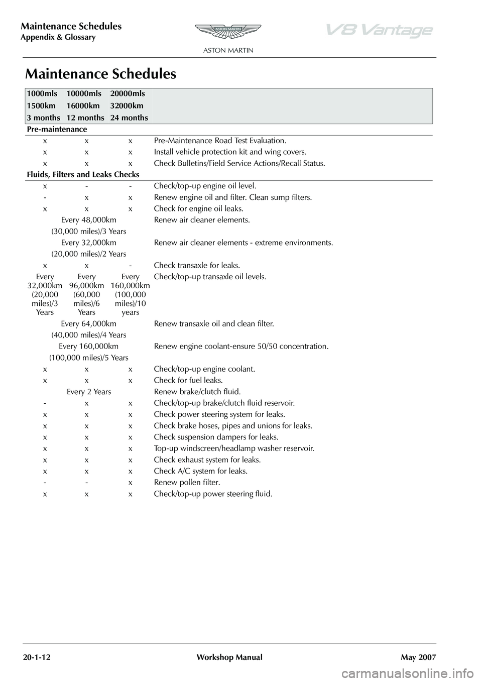
Maintenance Schedules
Appendix & Glossary20-1-12 Workshop Manual May 2007
Maintenance Schedules
1000mls
1500km
3 months10000mls
16000km
12 months20000mls
32000km
24 months
Pre-maintenance
x x x Pre-Maintenance Road Test Evaluation.
x x x Install vehicle protection kit and wing covers.
x x x Check Bulletins/Field Service Actions/Recall Status.
Fluids, Filters and Leaks Checks x - - Check/top-up engine oil level.- x x Renew engine oil and filter. Clean sump filters.
x x x Check for engine oil leaks. Every 48,000km
(30,000 miles)/3 Years Renew air cleaner elements.
Every 32,000km
(20,000 miles)/2 Years Renew air cleaner elements - extreme environments.
x x - Check transaxle for leaks.
Every
32,000km (20,000
miles)/3 Ye a r s Every
96,000km (60,000
miles)/6 Ye a r s Every
160,000km (100,000
miles)/10 years Check/top-up transaxle oil levels.
Every 64,000km
(40,000 miles)/4 Years Renew transaxle oil and clean filter.
Every 160,000km
(100,000 miles)/5 Years Renew engine coolant-ensure 50/50 concentration.
x x x Check/top-up engine coolant.
x x x Check for fuel leaks. Every 2 Years Renew brake/clutch fluid.
- x x Check/top-up brake/clutch fluid reservoir.
x x x Check power steering system for leaks.
x x x Check brake hoses, pipes and unions for leaks.
x x x Check suspension dampers for leaks.
x x x Top-up windscreen/headlamp washer reservoir.
x x x Check exhaust system for leaks.
x x x Check A/C system for leaks. - - x Renew pollen filter.
x x x Check/top-up power steering fluid.
Page 752 of 947
Torque Figures
Appendix & Glossary
May 2007 Workshop Manual 20-1-13
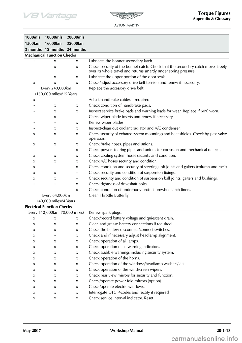
Mechanical Function Checks - x x Lubricate the bonnet secondary latch.
- x x Check security of the bonnet catch. Ch eck that the secondary catch moves freely
over its whole travel and returns smartly under spring pressure.
- x x Lubricate the upper portion of the door seals.
x x x Check/adjust accessory drive belt tension and renew if necessary. Every 240,000km
(150,000 miles)/15 Years Replace the accessory drive belt.
x - - Adjust handbrake cables if required. - x x Check condition of handbrake pads.
- x x Inspect service brake pads and warnin g leads for wear. Replace if 60% worn.
- x - Check wiper blade inserts and renew if necessary.
- - x Renew wiper blades.
- x x Inspect/clean out coolant radiator and A/C condenser.
x x x Check security of exhaust system mountings and heat shields. Check by-pass valve operation.
x x x Check brake hoses, pipes and unions. - - x Check power steering pipes and unions for corrosion and mechanical defects.
x x x Check cooling system hoses security and condition.
x x x Check A/C hoses security and condition.
x - x Check condition and security of steering unit joints and gaiters (column and rack).
x x - Check security and condition of suspension fixings.
x x - Check security and condition of susp ension ball joints, gaiters and bushings.
- - x Check tightness of driveshaft bolts.
- - x Check condition of underbody protection/wheel arch liners.
Every 64,000km
(40,000 miles)/4 Years Clean Throttle Butterfly
Electrical Function Checks Every 112,000km (70,000 miles) Renew spark plugs. x x x Check/record battery voltage and quiescent drain.
x x x Clean and grease battery connections if required.
x x x Check the battery disconnect/connect switches.
x - x Check and if necessary adjust headlamp alignment.
x x x Check operation of all lamps.
x x x Check operation of all warning indicators.
x x x Check audible warnings including security system.
x x x Check operation of the horns.
x x x Check operation of the windows/headlamp washers/jets.
x x x Check operation of the windscreen wipers.
x x x Check rear view mirrors for security and function.
x x x Check/operate power fold mirrors (option).
x x x Check/operate electric windows.
x x x Interrogate DTC P-codes and rectify if required
x x x Check service interval indicator. Reset.
1000mls
1500km
3 months10000mls
16000km
12 months20000mls
32000km
24 months
Page 791 of 947
Squeaks and Rattles Repair Manual
July 2010 Page 7 of 21
Steering Wheel Airbag Rattle
SRO: 01.20.CJ
Safe VINs: DBS - E01082, V8 Vantage - D13104, DB9 - A12179
Repair:
1. Put the Emotion Control Unit (ECU) into the docking station at position 2 to release the Electronic Steering
Column Lock (ESCL)
2. Disconnect the battery (refer to Workshop Manual procedure 14.01.CA).
WARNING:
WAIT FOR TWO MINUTES BEFORE YO U CONTINUE WITH THIS PROCEDURE. THIS IS TO MAKE SURE
THAT THERE IS NO POWER TO TH E AIRBAG SYSTEM. IF YOU DO NOT DO THIS, THE AIRBAG CAN
OPERATE SUDDENLY AND CAUSE INJURY
WARNING:
BE CAREFUL WHEN YOU HOLD AND MOVE THE AIRB AG UNIT. THE AIRBAG UNIT HAS AN EXPLOSIVE
CHARGE IN IT. IF YOU DO NOT HOLD THE UNIT CAREFULLY, THE CHARGE CAN OPERATE AND CAUSE
INJURY.
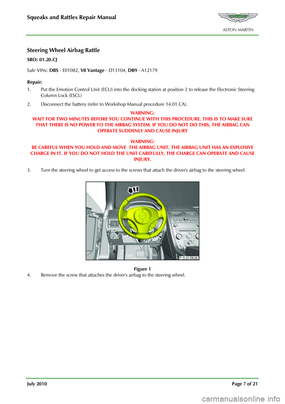
3. Turn the steering wheel to get access to the screws that attach the driver's airbag to the steering wheel.
Figure 1
4. Remove the screw that attaches the driver's airbag to the steering wheel.
Page 816 of 947

Electronics Training Programme
SYSTEM LAYOUT
V8 Vantage Layout
Bluetooth enabled and
paired phone
Bluetooth receiver module
Amplifier module
LED Indicator (Bluetooth display module)
Front speaker Switcher box
Microphone Steering column control
switches
Power Supply
Door speaker (drivers side) Door speaker
(passenger side)
11
Page 818 of 947

Electronics Training Programme
DB9 Layout
Bluetooth enabled and
paired phone
Bluetooth receiver module
Microphone
Amplifier module
Power Supply
Steering column control switches
LED Indicator (Bluetooth display module)
Door speaker (drivers side) Door speaker
(passenger side)
13
Page 820 of 947

Electronics Training Programme
INPUTS
The Bluetooth system relies on a number of signals it receives either from the car (via hard wiring) or
the users phone (via wireless Bluetooth communication network).
The Bluetooth system will only function if the us ers mobile phone has Bluetooth enabled and it is
‘paired’ to the car. For more information refer to the user’s guide for your mobile phone.
V8 Vantage Power Supplies
Description Supplied From Source Protection
Wakeup signal Central Electronic Module Comfort Relay F68 (5 Amp)
Power supply 1 Central Electronic Module Interior Lights Relay F46 (5Amp)
Power supply 2 Central Electronic Module Interior Lights Relay F46 (5Amp)
DB9 Power Supplies
Description Supplied From Source Protection
Wakeup signal Central Electronic Module Comfort Relay F69 (5 Amp)
Power supply 1 Central Electronic Module Interior Lights Relay F46 (5Amp)
Power supply 2 Central Electronic Module Interior Lights Relay F46 (5Amp)
V8 Vantage Signal Inputs
Input Description Signal Characteristic
MIC In Input signal from microphone Varying current signal direct from microphone
Keypad Steering wheel controls input Variable resistance to earth signal
DB9 Signal Inputs
Input Description Signal Characteristic
MIC In + Input signal from microphone Varying current signal supplied via amplifier
MIC In - Input signal from microphone Varying current signal supplied via amplifier
Keypad Steering wheel controls inpu t Variable resistance to earth
Screens
Some of the signals in and out of the Bluetooth modu le require screening to avoid interference being
picked up. A signal screen is a single wire running along side t he signal wire(s) which will absorb
electro magnetic interference (EMI).
The Bluetooth module on the V8 Vantage features only one screen so as to protect the signal from the
microphone. This screen wire is simply an earth but it is also used as a datum from which to reference
the microphone signal.
The Bluetooth module used on DB9’s features two screens. One is as on the V8 Vantage but is used
only as a screen (because the microphone signal from the amplifie r has two signal wires) and no
datum is required. The second screen on the module is used to screen the ‘Lineout’ signals to the
amplifier. As with the microphone scr een this wire is connected to earth.
15
Page 836 of 947
Electronics Training Programme
DIAGNOSTICS
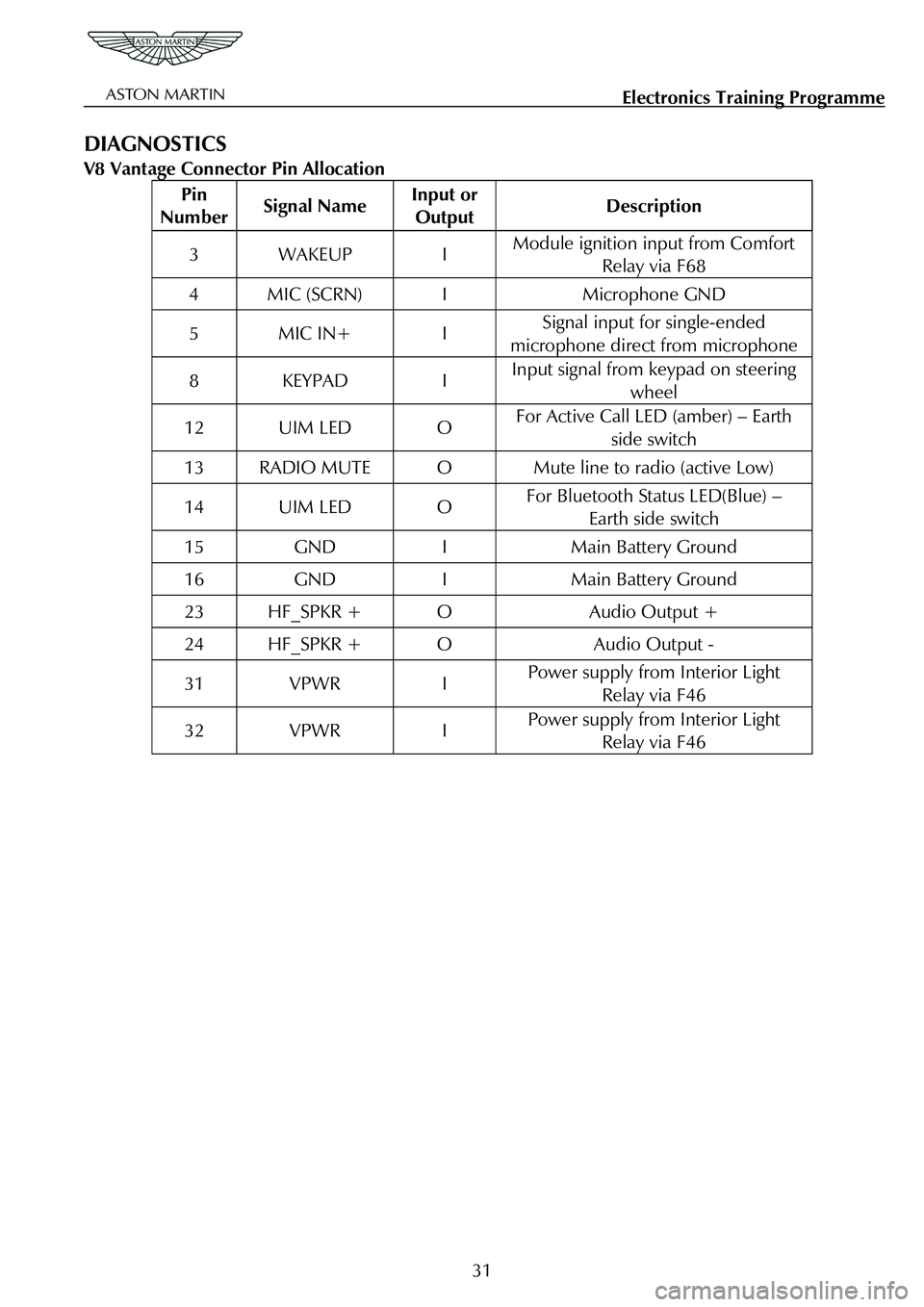
V8 Vantage Connector Pin Allocation
Pin
Number Signal Name Input or
Output Description
3 WAKEUP I Module ignition input from Comfort
Relay via F68
4 MIC (SCRN) I Microphone GND
5 MIC IN+ I Signal input for single-ended
microphone direct from microphone
8 KEYPAD I Input signal from keypad on steering wheel
12 UIM LED O For Active Call LED (amber) – Earth
side switch
13 RADIO MUTE O Mute line to radio (active Low)
14 UIM LED O For Bluetooth Status LED(Blue) – Earth side switch
15 GND I Main Battery Ground
16 GND I Main Battery Ground
23 HF_SPKR + O Audio Output +
24 HF_SPKR + O Audio Output -
31 VPWR I Power supply from Interior Light Relay via F46
32 VPWR I Power supply from Interior Light Relay via F46
31
Page 837 of 947
Electronics Training Programme
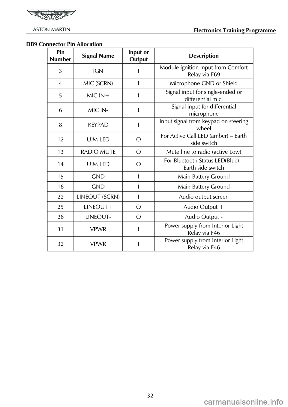
DB9 Connector Pin Allocation
Pin
Number Signal Name Input or
Output Description
3 IGN I Module ignition input from Comfort
Relay via F69
4 MIC (SCRN) I Microphone GND or Shield
5 MIC IN+ I Signal input for single-ended or
differential mic.
6 MIC IN- I Signal input for differential microphone
8 KEYPAD I Input signal from keypad on steering
wheel
12 UIM LED O For Active Call LED (amber) – Earth side switch
13 RADIO MUTE O Mute line to radio (active Low)
14 UIM LED O For Bluetooth Status LED(Blue) – Earth side switch
15 GND I Main Battery Ground
16 GND I Main Battery Ground
22 LINEOUT (SCRN) I Audio output screen
25 LINEOUT+ O Audio Output +
26 LINEOUT- O Audio Output -
31 VPWR I Power supply from Interior Light Relay via F46
32 VPWR I Power supply from Interior Light Relay via F46
32
Page 854 of 947
AML EOBD System Operation Summary
Rory O’Curry Aston Martin Lagonda CONFIDENTIAL 1 May 2009
[email protected] AML EOBD Monitors 07 ROC.doc Page 8 of 43
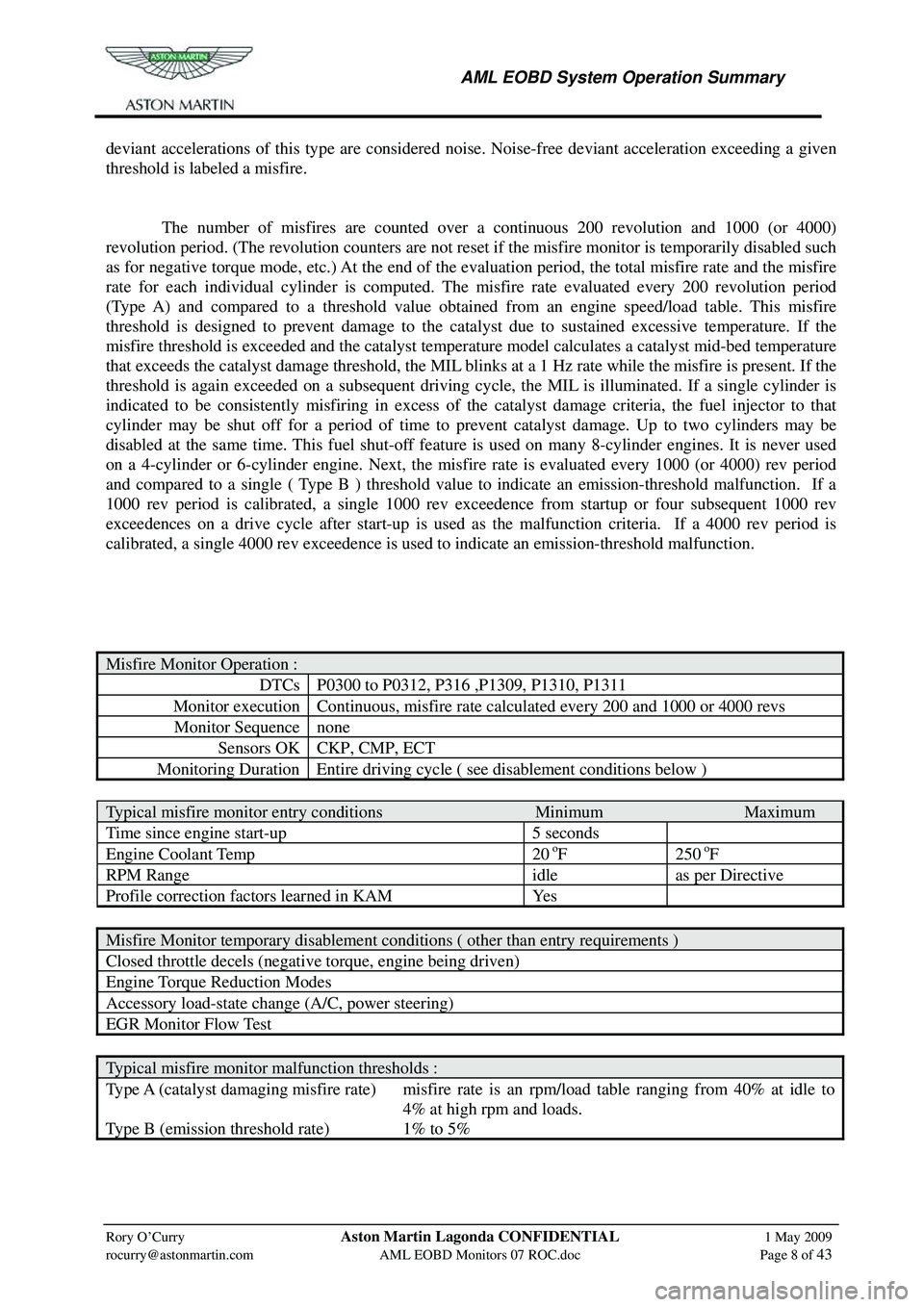
deviant accelerations of this type are considered noise. Noise-free deviant acceleration exceeding a given
threshold is labeled a misfire.
The number of misfires are counted over a continuous 200 revolution and 1000 (or 4000)
revolution period. (The revolution counters are not reset if the misfire monitor is temporarily disabled such
as for negative torque mode, etc.) At the end of the evaluation period, the total misfire rate and the misfire
rate for each individual cylinder is computed. The misfire rate evaluated every 200 revolution period
(Type A) and compared to a threshold value obtaine d from an engine speed/load table. This misfire
threshold is designed to prevent damage to the cat alyst due to sustained excessive temperature. If the
misfire threshold is exceeded and the catalyst temperature model calculates a catalyst mid-bed temperature
that exceeds the catalyst damage threshold, the MIL blinks at a 1 Hz rate while the misfire is present. If the
threshold is again exceeded on a subsequent driving cy cle, the MIL is illuminated. If a single cylinder is
indicated to be consistently misfiring in excess of the catalyst damage criteria, the fuel injector to that
cylinder may be shut off for a period of time to pr event catalyst damage. Up to two cylinders may be
disabled at the same time. This fuel shut-off feature is used on many 8-cylinder engines. It is never used
on a 4-cylinder or 6-cylinder engine. Next, the misf ire rate is evaluated every 1000 (or 4000) rev period
and compared to a single ( Type B ) threshold value to indicate an emission-threshold malfunction. If a
1000 rev period is calibrated, a single 1000 rev exceedence from startup or four subsequent 1000 rev
exceedences on a drive cycle after start-up is used as the malfunction criteria. If a 4000 rev period is
calibrated, a single 4000 rev exceedence is used to indicate an emission-threshold malfunction.
Misfire Monitor Operation :
DTCs P0300 to P0312, P316 ,P1309, P1310, P1311
Monitor execution Continuous, misfire rate calculated every 200 and 1000 or 4000 revs
Monitor Sequence none
Sensors OK CKP, CMP, ECT
Monitoring Duration Entire driving cycle ( see disablement conditions below )
Typical misfire monitor entry conditions Minimum Maximum
Time since engine start-up 5 seconds
Engine Coolant Temp 20 oF 250 oF
RPM Range idle as per Directive
Profile correction factors learned in KAM Yes
Misfire Monitor temporary disablement conditions ( other than entry requirements )
Closed throttle decels (negative torque, engine being driven)
Engine Torque Reduction Modes
Accessory load-state change (A/C, power steering)
EGR Monitor Flow Test
Typical misfire monitor malfunction thresholds :
Type A (catalyst damaging misfire rate) misfire rate is an rpm/load table ranging from 40% at idle to
4% at high rpm and loads.
Type B (emission threshold rate) 1% to 5%