battery location ASTON MARTIN V8 VANTAGE 2010 User Guide
[x] Cancel search | Manufacturer: ASTON MARTIN, Model Year: 2010, Model line: V8 VANTAGE, Model: ASTON MARTIN V8 VANTAGE 2010Pages: 947, PDF Size: 43.21 MB
Page 836 of 947

Electronics Training Programme
DIAGNOSTICS
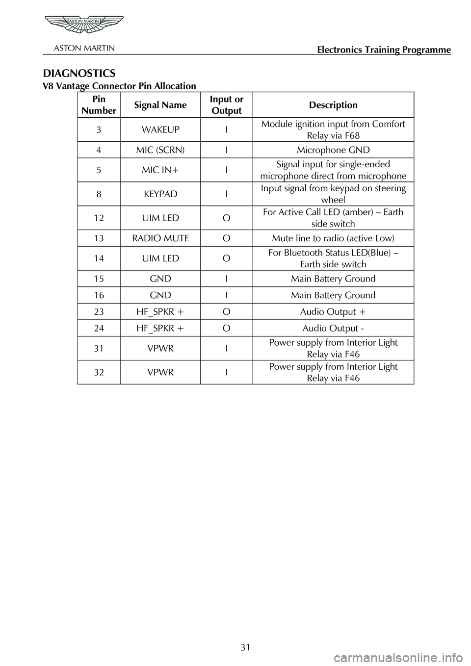
V8 Vantage Connector Pin Allocation
Pin
Number Signal Name Input or
Output Description
3 WAKEUP I Module ignition input from Comfort
Relay via F68
4 MIC (SCRN) I Microphone GND
5 MIC IN+ I Signal input for single-ended
microphone direct from microphone
8 KEYPAD I Input signal from keypad on steering wheel
12 UIM LED O For Active Call LED (amber) – Earth
side switch
13 RADIO MUTE O Mute line to radio (active Low)
14 UIM LED O For Bluetooth Status LED(Blue) – Earth side switch
15 GND I Main Battery Ground
16 GND I Main Battery Ground
23 HF_SPKR + O Audio Output +
24 HF_SPKR + O Audio Output -
31 VPWR I Power supply from Interior Light Relay via F46
32 VPWR I Power supply from Interior Light Relay via F46
31
Page 837 of 947

Electronics Training Programme
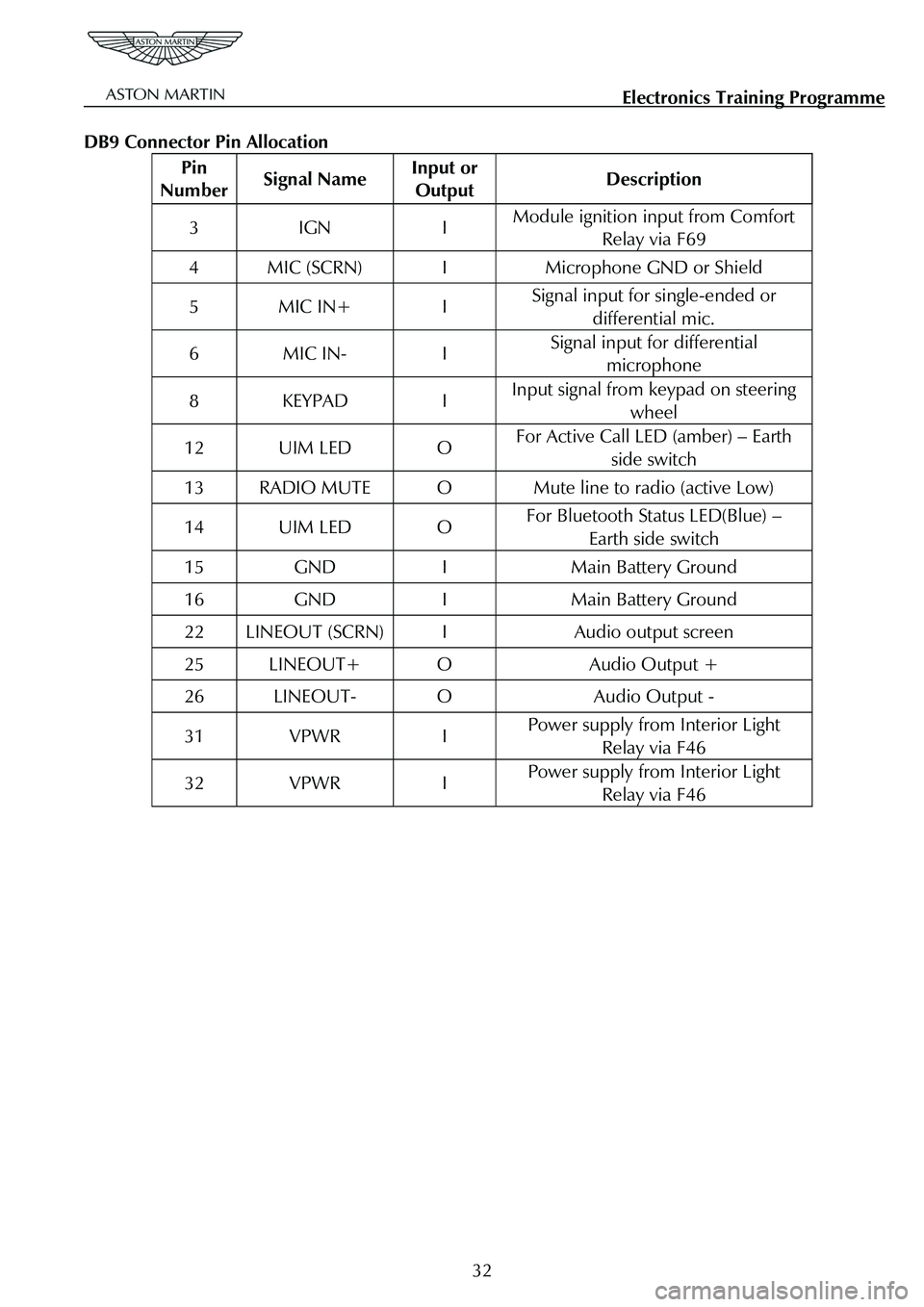
DB9 Connector Pin Allocation
Pin
Number Signal Name Input or
Output Description
3 IGN I Module ignition input from Comfort
Relay via F69
4 MIC (SCRN) I Microphone GND or Shield
5 MIC IN+ I Signal input for single-ended or
differential mic.
6 MIC IN- I Signal input for differential microphone
8 KEYPAD I Input signal from keypad on steering
wheel
12 UIM LED O For Active Call LED (amber) – Earth side switch
13 RADIO MUTE O Mute line to radio (active Low)
14 UIM LED O For Bluetooth Status LED(Blue) – Earth side switch
15 GND I Main Battery Ground
16 GND I Main Battery Ground
22 LINEOUT (SCRN) I Audio output screen
25 LINEOUT+ O Audio Output +
26 LINEOUT- O Audio Output -
31 VPWR I Power supply from Interior Light Relay via F46
32 VPWR I Power supply from Interior Light Relay via F46
32
Page 899 of 947

Aston Martin V8 Vantage 2009 MY EOBD DocumentationAston Martin/Ford Confidential
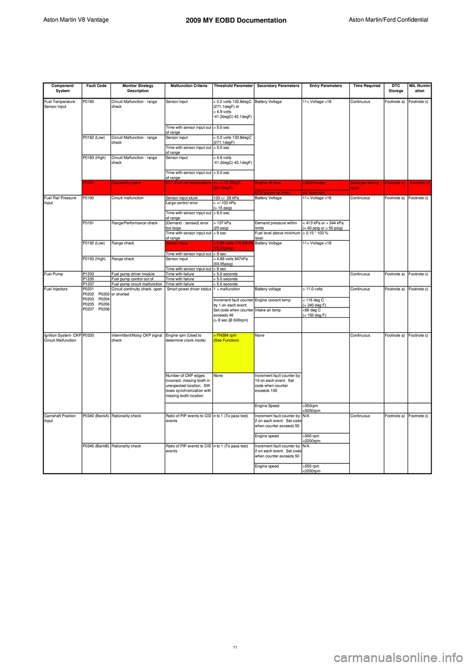
Component/ System Fault Code Monitor Strategy
Description Malfunction Criteria Threshold Parameter Secondary Parameters Entry Parameters Time Required DTC
StorageMIL Illumin-
ation
Sensor input < 0.2 volts 132.8degC
(271.1degF) or
> 4.9 volts
-41.2degC(-42.1degF)
Time with sensor input out
of range > 5.0 sec
Sensor input < 0.2 volts 132.8degC
(271.1degF)
Time with sensor input out
of range > 5.0 sec
Sensor input > 4.9 volts
-41.2degC(-42.1degF)
Time with sensor input out
of range > 5.0 sec
Engine off time >360minutes
ECU power up timer >0.1seconds
Sensor input stuck 103 +/- 59 kPa
Large control error > +/-103 kPa (> 15 psig)
Time with sensor input out
of range > 8.0 sec
(Demand - sensed) error
too large > 137 kPa
(20 psig)Demand pressure within
limits < 413 kPa or > 344 kPa
(< 60 psig or > 50 psig)
Time with sensor input out
of range > 8 sec
Fuel level above minimum
level > 0.15 * 100 %
Sensor input < 0.95 volts 174.23kPa
(25.33psig)
Time with sensor input out > 8 sec
Sensor input > 4.88 volts 647kPa
(93.95psig)
Time with sensor input out > 8 sec
P1233 Fuel pump driver module Time with failure > 5.0 seconds
P1235 Fuel pump control out of Time with failure > 5.0 seconds
P1237 Fuel pump circuit malfunction Time with failure > 5.0 seconds 1 = malfunction Battery voltage> 11.0 volts
Engine coolant temp < 116 deg C (< 240 deg F)
Intake air temp <66 deg C
(< 150 deg F)
Engine rpm (Used to
determine crank mode) > FN384 rpm
(See Function)None
Number of CKP edges
incorrect, missing tooth in
unexpected location. SW
loses synchronization with
missing tooth location None
Increment fault counter by
10 on each event. Set
code when counter
exceeds 100
Engine Speed >550rpm
<5000rpm
Increment fault counter by
2 on each event. Set code
when counter exceeds 50 N/A
Engine speed >550 rpm
<2200rpm
Increment fault counter by
2 on each event. Set code
when counter exceeds 50 N/A
Engine speed >550 rpm
<2200rpm Footnote a) Footnote c)
Continuous
<> +/-12.3degC
(54.1degF) Once per driving
cycle
Fuel Temperature
Sensor Input
ECT-Fuel rail temperature
Circuit Malfunction - range
check
Circuit Malfunction - range
check
Circuit Malfunction - range
check
P0180
P0182 (Low)
P0181 Rationality check
P0183 (High)
Ignition System- CKP
Circuit Malfunction P0320 Intermittent/Noisy CKP signal
check Footnote c)
Footnote c)
Ratio of PIP events to CID
events Continuous Footnote a) Footnote c)
n to 1 (To pass test)
n to 1 (To pass test)
Increment fault counter
by 1 on each event.
Set code when counter
exceeds 40
(> 8 sec @ 600rpm)
Smart power driver status
P0340 (BankA)
P0345 (BankB) Circuit continuity check, open
or shorted
P0201
P0202 P0203
P0203 P0204
P0205 P0206
P0207 P0208
Camshaft Position
Input Rationality check
Rationality checkRatio of PIP events to CID
events Continuous
Footnote a)
Footnote c)
Continuous Footnote a) Footnote c) Footnote a)
Battery Voltage 11< Voltage <18
11< Voltage <18 Continuous Footnote a) Footnote c)
11< Voltage <18
Circuit malfunction
Battery Voltage
Battery Voltage
Range check
Continuous Footnote a)
Fuel Injectors
Fuel Rail Pressure
Input
P0190
P0191
P0192 (Low)
P0193 (High)
Fuel Pump Range check
Range/Performance check
11
Page 945 of 947

Service Bulletin SB0286V2
December 2009 Page 3 of 5
Note: The location of the water leak can be difficult to find.
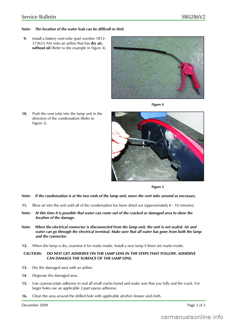
9. Install a battery vent tube (part number 1R12-
372635-AA) onto an airline that has dry air,
without oil (Refer to the example in Figure 4).
Figure 4
10. Push the vent tube into the lamp unit in the
direction of the condensation (Refer to
Figure 5).
Figure 5
Note: If the condensation is at the two ends of the la mp unit, move the vent tube around as necessary.
11. Blow air into the unit until all of the condensati on has been dried out (approximately 6 - 10 minutes).
Note: At this time it is possible that water can come out of the cracked or damaged area to show the
location of the damage.
Note: When the electrical connector is disconnected from the lamp unit, the unit is not sealed. Air and
water can go through the electrical terminal. Make sure that all water has gone from both the lamp
and the connector.
12. When the lamp is dry, examine it for marks inside. Install a new lamp if there are marks inside.
CAUTION: DO NOT GET ADHESIVE ON THE LAMP LENS IN THE STEPS THAT FOLLOW. ADHESIVE
CAN DAMAGE THE SURFACE OF THE LAMP LENS.
13. Dry the damaged area with an airline.
14. Degrease the damaged area.
15. Use cyanoacrylate adhesive to seal all small cracks fo und and make sure that you fully seal the crack. For
larger holes use an applicab le 2-part epoxy adhesive.
16. Clean the area around the drilled hole with applicable alcohol cleaner and cloth.