battery location ASTON MARTIN V8 VANTAGE 2010 Workshop Manual
[x] Cancel search | Manufacturer: ASTON MARTIN, Model Year: 2010, Model line: V8 VANTAGE, Model: ASTON MARTIN V8 VANTAGE 2010Pages: 947, PDF Size: 43.21 MB
Page 5 of 947

Contents
Issue 5, January 2010 Workshop Manual 0-0-5
Introduction
Contents ................................................................. 0-3
Welcome................................................................ 0-0-6 Chapters ................................................................. 0-6Chapter Navigation ................................................ 0-6
Page Numbering ..................................................... 0-6
Systems Classification Coding ................................ 0-6
Special Tools.......................................................... 0-0-6 Location References................................................ 0-6
Warnings, Cautions and Notes .............................. 0-0-6 Repairs and Replacements ..................................... 0-6
Safety Precautions ................................................. 0-0-7 Battery Disconnection ............................................ 0-7
Air Conditioning (A/C) System ................................ 0-7
Chemical Handling and Storage ............................. 0-7
Electrical Equipment .............................................. 0-0-7 Exhaust Fumes ........................................................ 0-7
Fire Precautions ...................................................... 0-7
Tools and Equipment............................................. 0-0-8 Used Engine Oil...................................................... 0-8
Health protection precautions................................ 0-8
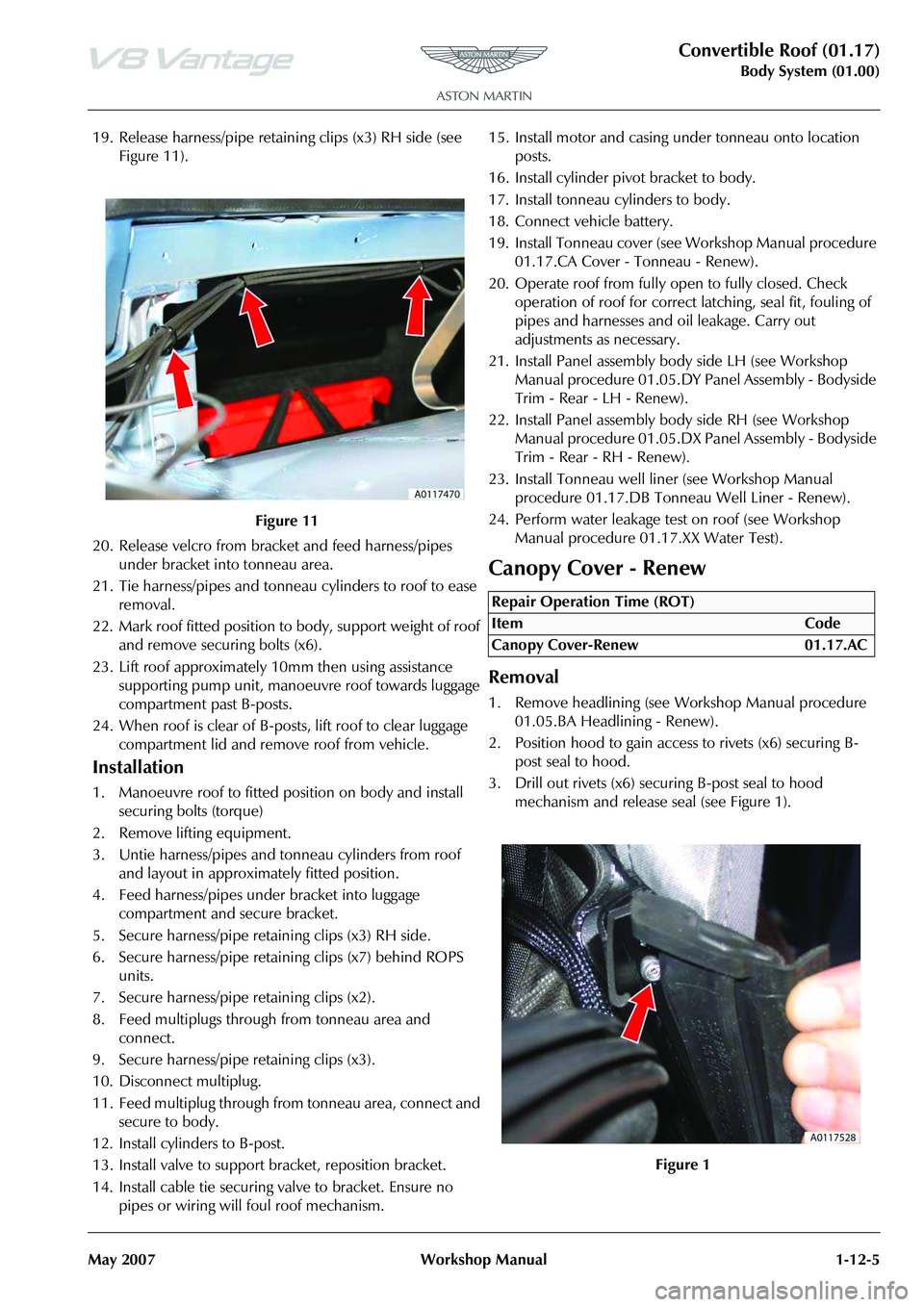
Environmental Protection ....................................... 0-8
Lifting and Jacking ................................................. 0-0-9 Safety ...................................................................... 0-9
Jacking Points ........................................................ 0-0-9
Lifting ..................................................................... 0-0-9 Workshop Hoist ..................................................... 0-9
Workshop Jack....................................................... 0-9
Stands .................................................................... 0-9
Vehicle Recovery.................................................. 0-0-10 General ................................................................. 0-10
Transporting ......................................................... 0-10Suspended Towing............................................... 0-10
Adhere to Towing Regulations.............................. 0-10
Towing by Another Vehicle .................................. 0-10
Vehicle Identification Number ............................ 0-0-11
VIN Number Location .......................................... 0-11
Engine Number..................................................... 0-12
Gearbox Number .................................................. 0-12
Page 143 of 947

Convertible Roof (01.17)
Body System (01.00)
May 2007 Workshop Manual 1-12-5
19. Release harness/pipe retaining clips (x3) RH side (see Figure 11).
20. Release velcro from bracket and feed harness/pipes under bracket into tonneau area.
21. Tie harness/pipes and tonneau cylinders to roof to ease removal.
22. Mark roof fitted position to body, support weight of roof and remove securing bolts (x6).
23. Lift roof approximately 10mm then using assistance
supporting pump unit, manoeuvre roof towards luggage
compartment past B-posts.
24. When roof is clear of B-post s, lift roof to clear luggage
compartment lid and remove roof from vehicle.
Installation
1. Manoeuvre roof to fitted position on body and install securing bolts (torque)
2. Remove lifting equipment.
3. Untie harness/pipes and tonneau cylinders from roof and layout in approximately fitted position.
4. Feed harness/pipes under bracket into luggage compartment and secure bracket.
5. Secure harness/pipe retaining clips (x3) RH side.
6. Secure harness/pipe retaining clips (x7) behind ROPS units.
7. Secure harness/pipe retaining clips (x2).
8. Feed multiplugs through from tonneau area and connect.
9. Secure harness/pipe retaining clips (x3).
10. Disconnect multiplug.
11. Feed multiplug through from tonneau area, connect and secure to body.
12. Install cylinders to B-post.
13. Install valve to support bracket, reposition bracket.
14. Install cable tie securing valve to bracket. Ensure no pipes or wiring will foul roof mechanism. 15. Install motor and casing under tonneau onto location
posts.
16. Install cylinder pivot bracket to body.
17. Install tonneau cylinders to body.
18. Connect vehicle battery.
19. Install Tonneau cover (see Workshop Manual procedure 01.17.CA Cover - Tonneau - Renew).
20. Operate roof from fully open to fully closed. Check operation of roof for correct latching, seal fit, fouling of
pipes and harnesses and oil leakage. Carry out
adjustments as necessary.
21. Install Panel assembly bo dy side LH (see Workshop
Manual procedure 01.05.DY Panel Assembly - Bodyside
Trim - Rear - LH - Renew).
22. Install Panel assembly body side RH (see Workshop Manual procedure 01.05.DX Pa nel Assembly - Bodyside
Trim - Rear - RH - Renew).
23. Install Tonneau well line r (see Workshop Manual
procedure 01.17.DB Tonneau Well Liner - Renew).
24. Perform water leakage test on roof (see Workshop Manual procedure 01.17.XX Water Test).
Canopy Cover - Renew
Removal
1. Remove headlining (see Workshop Manual procedure
01.05.BA Headlining - Renew).
2. Position hood to gain access to rivets (x6) securing B- post seal to hood.
3. Drill out rivets (x6) secu ring B-post seal to hood
mechanism and release seal (see Figure 1).
Figure 11
Repair Operation Time (ROT)
Page 171 of 947

Convertible Roof (01.17)
Body System (01.00)
May 2007 Workshop Manual 1-12-33
small quantity of oil replace plug and re-check level (see
Figure 1).
2. Install pipe to approximate route on vehicle and install cable ties.
3. Clean pipe and install pipe to pump then slide retaining plate into place and tighten screws (pipes and locations
are numbered).
4. Install pump casing and secure velcro.
5. Install pump and casing under tonneau onto location posts.
6. Install cylinder pivot bracket and connect cylinder to bracket.
7. Move tonneau well liner ar ound lower cylinder fixing
and pump casing and secure velcro.
8. Install trim clip and position tonneau lining stiffening rod.
9. Install harness/pipe retaining clips (x9) behind ROPS units.
10. Install harness/pipe re taining clips LH (x2).
11. Install harness/pipe re taining clips RH (x3).
12. Attach pipes to guide stri ng, feed pipes through roof
frame and remove string.
13. Position pipes to cylinder and secure with clips.
14. Secure pipes and wires to cylinder with cable tie.
15. Install new clips securi ng pipes to roof frame.
16. Connect battery.
17. Install Panel quarter trim lower (see Workshop Manual procedure 01.05.CR Panel Assembly - Quarter Trim
Lower - RH - Renew).
18. Restore roof and tonneau to original position.LH Rear Main Hydraulic Cylinder Pipe -
Renew
Removal
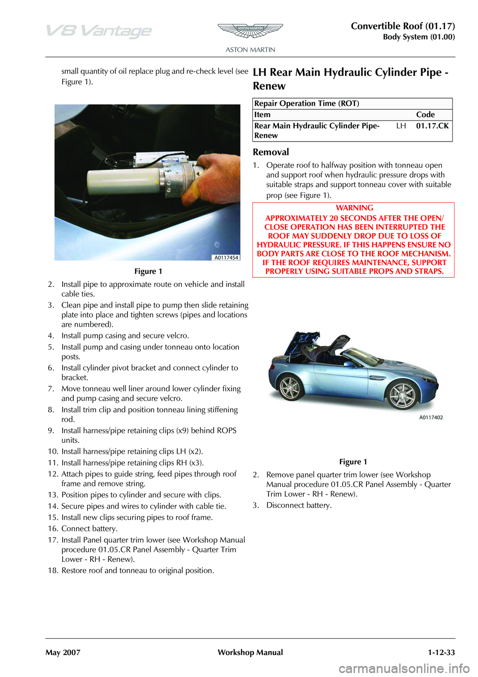
1. Operate roof to halfway position with tonneau open and support roof when hydraulic pressure drops with
suitable straps and support tonneau cover with suitable
prop (see Figure 1).
2. Remove panel quarter trim lower (see Workshop Manual procedure 01.05.CR Panel Assembly - Quarter
Trim Lower - RH - Renew).
3. Disconnect battery.
Figure 1
Repair Operation Time (ROT)
Page 181 of 947

Convertible Roof (01.17)
Body System (01.00)
May 2007 Workshop Manual 1-12-43
small quantity of oil replace plug and re-check level (see
Figure 1).
2. Install pipe to approximate route on vehicle and install cable ties.
3. Clean pipe and install pipe to pump. Slide retaining plate into place and tighten screws (pipes and locations
are numbered).
4. Install pump casing and secure velcro.
5. Install pump and casing under tonneau onto location posts.
6. Install cylinder pivot bracket and connect cylinder to bracket.
7. Move tonneau well liner ar ound lower cylinder fixing
and pump casing and secure velcro.
8. Install trim clip and position tonneau lining stiffening rod.
9. Attach pipes to guide stri ng, feed pipes through roof
frame and remove string.
10. Position pipes to cylinder and secure with clips.
11. Secure pipes and wires to cylinder with cable tie.
12. Install new clips securi ng pipes to roof frame.
13. Connect battery.
14. Install Panel quarter trim lower (see Workshop Manual procedure 01.05.CR Panel Assembly - Quarter Trim
Lower - RH - Renew).
15. Restore roof and tonneau to original position.
LH Front Hydraulic Cylinder Pipe -
Renew
Removal
1. Operate roof to halfway position with tonneau open then support roof when hydr aulic pressure drops with
suitable straps and support tonneau cover with suitable
prop (see Figure 1).
2. Remove wind deflector (see Workshop Manual
procedure 01.17.DA Wind Deflector - Renew).
3. Disconnect battery.
4. Remove lower cover (screw x1) (see Figure 2).
Figure 1
Repair Operation Time (ROT)
WA R N I N G
APPROXIMATELY 20 SECO NDS AFTER THE OPEN/
CLOSE OPERATION HAS BEEN INTERRUPTED THE ROOF MAY SUDDENLY DROP DUE TO LOSS OF
HYDRAULIC PRESSURE. IF THIS HAPPENS ENSURE NO
BODY PARTS ARE CLOSE TO THE ROOF MECHANISM. IF THE ROOF REQUIRES MAINTENANCE, SUPPORT PROPERLY USING SUITABLE PROPS AND STRAPS.
Figure 1
Figure 2
Page 188 of 947

Convertible Roof (01.17)
Body System (01.00)1-12-50 Workshop Manual May 2007
small quantity of oil replace plug and re-check level (see
Figure 1).
2. Install pipe to approximate route on vehicle and install cable ties.
3. Clean pipe and install pipe to pump then slide retaining plate into place and tighten screws (pipes and locations
are numbered).
4. Install pump casing and secure velcro.
5. Install pump and casing under tonneau onto location posts.
6. Install cylinder pivot bracket and connect cylinder to bracket.
7. Move tonneau well liner arou nd lower cylinder fixing
and pump casing and secure velcro.
8. Install trim clip and positi on tonneau lining stiffening
rod.
9. Install harness/pipe retaining clips (x9) behind ROPS units.
10. Install harness/pipe retaining clips LH (x2).
11. Install harness/pipe retaining clips RH (x3).
12. Attach pipes to guide stri ng, feed pipes through roof
frame and remove string.
13. Position pipes to cylinder and secure with clips.
14. Secure pipes and wires to cylinder with cable ties
15. Install pipe under keeper plate, install and tighten
screws.
16. Install new clips securing pipes to roof frame.
17. Install lower cover.
18. Connect battery.
19. Install Wind deflector (see Workshop Manual procedure 01.17.DA Wind Deflector - Renew).
20. Restore roof and tonneau to original positionRH Front Hydraulic Cylinder Pipe -
Renew
Removal
1. Operate roof to halfway position with tonneau open then support roof when hydraulic pressure drops with
suitable straps and support tonneau cover with suitable
prop (see Figure 1).
2. Remove wind deflector (see Workshop Manual procedure 01.17.DA Wind Deflector - Renew).
3. Disconnect battery.
Figure 1
Repair Operation Time (ROT)
ItemCode
Front Hydraulic Cylinder Pipe-Renew RH01.17.CQ
WAR NI NG
APPROXIMATELY 20 SECONDS AFTER THE OPEN/
CLOSE OPERATION HAS BEEN INTERRUPTED THE
ROOF MAY SUDDENLY DROP DUE TO LOSS OF
HYDRAULIC PRESSURE. IF THIS HAPPENS ENSURE NO
BODY PARTS ARE CLOSE TO THE ROOF MECHANISM.
IF THE ROOF REQUIRES MAINTENANCE, SUPPORT
PROPERLY USING SUITABLE PROPS AND STRAPS.
Figure 1
Page 194 of 947

Convertible Roof (01.17)
Body System (01.00)1-12-56 Workshop Manual May 2007
20. Remove cable ties and remove pipe from vehicle (see Figure 12).
Installation
1. Check oil level and top-up if necessary by removing reservoir end plug with pump in upright position, add
small quantity of oil replace plug and re-check level (see
Figure 1).
2. Install pipe to approximate route on vehicle and install cable ties.
3. Clean pipe and install pipe to pump then slide retaining plate into place and tighten screws (pipes and locations
are numbered).
4. Install pump casing and secure velcro.
5. Install pump and casing under tonneau onto location posts.
6. Install cylinder pivot bracket and connect cylinder to bracket. 7. Move tonneau well liner around lower cylinder fixing
and pump casing and secure velcro
8. Install trim clip and position tonneau lining stiffening rod.
9. Install harness/pipe retaining clips RH (x3).
10. Attach pipes to guide string, feed pipes through roof frame and remove string.
11. Position pipes to cylinder and secure with clips.
12. Secure pipes and wires to cylinder with cable ties
13. Install pipe under keeper plate, install and tighten screws.
14. Install new clips securi ng pipes to roof frame.
15. Install lower cover.
16. Connect battery.
17. Restore roof and tonneau to original position
RH/LH Rear Hydraulic Tonneau Cylinder
Pipe - Renew
Removal
1. Operate roof to halfway position with tonneau open then support roof when hydraulic pressure drops with
suitable straps and support tonneau cover with suitable
prop (see Figure 1).
Figure 12
Figure 1
Repair Operation Time (ROT)
ItemCode
Rear Hydraulic Tonneau Cylinder Pipe-
Renew LH
01.17.CS
Rear Hydraulic Tonneau Cylinder Pipe-
Renew RH
01.17.CV
WAR NI NG
APPROXIMATELY 20 SECONDS AFTER THE OPEN/
CLOSE OPERATION HAS BEEN INTERRUPTED THE
ROOF MAY SUDDENLY DROP DUE TO LOSS OF
HYDRAULIC PRESSURE. IF THIS HAPPENS ENSURE NO
BODY PARTS ARE CLOSE TO THE ROOF MECHANISM.
IF THE ROOF REQUIRES MAINTENANCE, SUPPORT
PROPERLY USING SUITABLE PROPS AND STRAPS.
Page 198 of 947

Convertible Roof (01.17)
Body System (01.00)1-12-60 Workshop Manual May 2007
small quantity of oil replace plug and re-check level (see
Figure 1).
2. Install pipe to approx imate route on vehicle.
3. Clean pipe and install pipe to pump then slide retaining plate into place and tighten screws (pipes and locations
are numbered).
4. Clean pipe, connect to cylinder and secure clip.
5. Install cable ties securing pipes and wires to cylinder.
6. Install harness/pipe retaining clips.
7. Position tonneau liner to body and install clips.
8. Install pump casing and secure velcro.
9. Install pump and casing under tonneau onto location posts.
10. Install cylinder pivot bracket and connect cylinder to bracket.
11. Move tonneau well liner arou nd lower cylinder fixing
and pump casing and secure velcro.
12. Install trim clip and positi on tonneau lining stiffening
rod.
13. Connect battery.
14. Restore roof and tonneau to original position
LH/RH Front Hydraulic Tonneau Cylinder
Pipe - Renew
Removal
1. Operate roof to halfway position with tonneau open then support roof when hydraulic pressure drops with suitable straps and support
tonneau cover with suitable
prop (see Figure 1).
2. Disconnect battery.
3. Remove trim clip and releas e tonneau lining stiffening
rod (see Figure 2).
4. Release velcro and move to nneau well liner aside to
e x p o s e l o w e r c y l i n d e r f i x i n g a n d m o t o r c a s i n g .
Figure 1
Repair Operation Time (ROT)
WAR NI NG
APPROXIMATELY 20 SECONDS AFTER THE OPEN/
CLOSE OPERATION HAS BEEN INTERRUPTED THE
ROOF MAY SUDDENLY DROP DUE TO LOSS OF
HYDRAULIC PRESSURE. IF THIS HAPPENS ENSURE NO
BODY PARTS ARE CLOSE TO THE ROOF MECHANISM.
IF THE ROOF REQUIRES MAINTENANCE, SUPPORT
PROPERLY USING SUITABLE PROPS AND STRAPS.
Figure 1
Figure 2
Page 201 of 947

Convertible Roof (01.17)
Body System (01.00)
May 2007 Workshop Manual 1-12-63
15. Remove harness/pipe retaining clips (x3) RH/LH (see Figure 11).
16. Remove pipe from vehicle.
Installation
1. Check oil level and top-up if necessary by removing
reservoir end plug with pump in upright position, add
small quantity of oil replace plug and re-check level (see
Figure 1).
2. Install pipe to approximate route on vehicle.
3. Clean pipe and install pipe to pump then slide retaining plate into place and tighten screws (pipes and locations
are numbered).
4. Clean pipe, connect to cylinder and secure clip.
5. Install cable ties securing pipes and wires to cylinder.
6. Install harness/pipe retaining clips.
7. Position tonneau liner to body and install clips.
8. Install pump casing and secure velcro. 9. Install pump and casing under tonneau onto location
posts.
10. Install cylinder pivot brack et and connect cylinder to
bracket.
11. Move tonneau well liner arou nd lower cylinder fixing
and pump casing and secure velcro.
12. Install trim clip and positi on tonneau lining stiffening
rod.
13. Connect battery.
14. Restore roof and tonneau to original position
Hydraulic Cylinder Valve to Pump Pipe -
Renew
Removal
1. Operate roof to halfway position with tonneau open then support roof when hydr aulic pressure drops with
suitable straps and support tonneau cover with suitable
prop (see Figure 1).
2. Disconnect battery.
Figure 11
Figure 1
Repair Operation Time (ROT)
Page 204 of 947

Convertible Roof (01.17)
Body System (01.00)1-12-66 Workshop Manual May 2007
14. Loosen (x6) screws on pump retaining plate (see Figure
10).
15. Slide retaining plate, discon nect pipe from pump (pipes
and locations are numbered).
16. Remove cable ties and remove pipe from vehicle (see Figure 11).
Installation
1. Check oil level and top-up if necessary by removing reservoir end plug with pump in upright position, add small quantity of oil replace plug and re-check level (see
Figure 1).
2. Install pipe to approximate route on vehicle and install
cable ties.
3. Clean pipe and install pipe to pump then slide retaining plate into place and tighten screws. (pipes and locations
are numbered).
4. Install motor casing and secure velcro.
5. Install motor and casing under tonneau onto location posts.
6. Install cylinder pivot bracket and connect cylinder to bracket.
7. Move tonneau well liner around lower cylinder fixing and motor casing and secure velcro
8. Position tonneau liner to body and install clips.
9. Install trim clip and position tonneau lining stiffening rod.
10. Clean pipe, connect pipe to valve, slide retaining plate
and tighten screw.
11. Install valve to support bracket, reposition bracket.
12. Install cable tie securing valve to bracket. Ensure no
pipes or wiring will foul roof mechanism.
13. Connect battery.
14. Restore roof and tonneau to original positionWind Deflector - Renew
Removal
1. Operate roof to halfway position with tonneau open then support roof when hydraulic pressure drops with
Figure 10
Figure 11
Figure 1
Repair Operation Time (ROT)
ItemCode
Wind Deflector-Renew 01.17.DA
Page 645 of 947

Air Conditioning (A/C) System (12.03)
Climate Control (12.00)
12-3-12 Workshop Manual May 2007
Leaks
Faults associated with low refrigerant charge weight and low pressure may be caused by leakage. Leaks traced to
mechanical connections may be caused by torque relaxation or joint face contamination. Evidence of oil around such
areas is an indicator of leakage.
Leak Detection
Fluorescent Tracer Dye - A fluorescent tracer dye is incorporated into th e refrigeration system and can be checked for
non-apparent leaks by scanning with a high intensity ultraviolet lamp. The location of leaks can be pinpointed by the bright
yellow glow of the tracer dye.
Automatic Refrigerant Leak Detector - (various manufacturers) Hand-held, portable, battery operated leak detector.
Place in and around A/C system to detect refrigerant leaks.
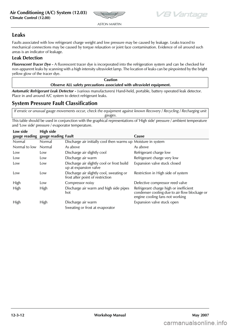
System Pressure Fault Classification
This table should be used in conjunction with the graphical representations of 'High side' pressure / ambient temperature
and 'Low side' pressure / evaporator temperature. Caution
Observe ALL safety precautions associ ated with ultraviolet equipment.
If erratic or unusual gauge movements occur, check the equipment against known Recovery / Recycling / Recharging unit
gauges.
Low side
gauge readingHigh side
gauge reading
Fault
Cause
Normal Normal Discharge air initially c ool then warms up Moisture in system
Normal to low Normal As above As above
Low Low Discharge air slightly cool Refrigerant charge low
Low Low Discharge air warm Refrigerant charge very low
Low Low Discharge air slightly cool or frost build up at expansion valve Expansion valve stuck closed
Low Low Discharge air slightly cool, sweating or frost after point of restriction Restriction in High side of system
High Low Compressor noisy Defective compressor reed valve
High High Discharge air warm and high side pipes hot Refrigerant charge high or inefficient
condenser cooling due to air flow blockage or
engine cooling fans not working
High High Discharge air warm
Sweating or frost at evaporator Expansion valve stuck open