brakes ASTON MARTIN V8 VANTAGE 2010 User Guide
[x] Cancel search | Manufacturer: ASTON MARTIN, Model Year: 2010, Model line: V8 VANTAGE, Model: ASTON MARTIN V8 VANTAGE 2010Pages: 947, PDF Size: 43.21 MB
Page 489 of 947

Brake Actuation System (06.06)
Brake System (06.00)
May 2007 Workshop Manual 6-6-3
7. Fill reservoir.
8. Bleed Brakes (see Workshop Manual procedure 06.06.AD Pad Kit - Manual Brake and Clutch Pedal -
Renew).
LHD-Brake Master Cylinder Assembly-
Renew
Removal
1. Remove corner cross brace.
2. Move expansion tank aside for access (bolt x1, nut x1, hose clips x2, multiplug x1).
3. Disconnect clutch reservoir feed pipe.
4. Disconnect multiplugs (x2).
5. Disconnect brake pipes from master cylinder (move aside).
6. Remove reservoir holding screw for access to master cylinder retaining nut.
7. Remove master cylinder from booster (nuts x2).
Installation
1. On new master cylinder - Remove reservoir holding screw for access to master cylinder retaining nut.
2. Install master cylinder to booster (nuts x2).
3. Install reservoir holding screw for access to master cylinder retaining nut.
4. Connect brake pipes to master cylinder.
5. Connect clutch reservoir feed pipe. 6. Connect multiplugs (x2).
7. Install expansion tank aside (bolt x1, nut x1, hose clips
x2, multiplug x1).
8. Install corner cross brace (torque) (only fully tighten
when vehicle on level floor).
9. Bleed Brakes (see Workshop Manual procedure 06.06.AD Pad Kit - Manual Brake and Clutch Pedal -
Renew).
10. Top-up coolant.
Clutch Master Cylinder Assembly-Renew
Removal
1. Move drivers seat fully rearward.
2. Remove clevis pin and clip.
3. Remove cylinder securing nuts (x2).
4. Remove fluid (syringe) from brake master cylinder to
below clutch level.
5. Remove corner cross brace.
6. Move expansion tank aside for access (bolt x1, nut x1, hose clips x2, multiplug x1).
7. Disconnect clutch reservoir feed pipe.
8. Disconnect clutch pipe quick fit (pull clip back) and move aside.
9. Remove cylinder assembly.
10. Remove and discard O-ring seal from master cylinder.
11. Split components
12. Remove pipe from cy linder (mark position).
Repair Operation Time (ROT)
Repair Operation Time (ROT)
Page 501 of 947

Power Brake System (06.07)
Brake System (06.00)
May 2007 Workshop Manual 6-7-1
Brake System (06.00)
Power Brake System (06.07)
Brake Booster
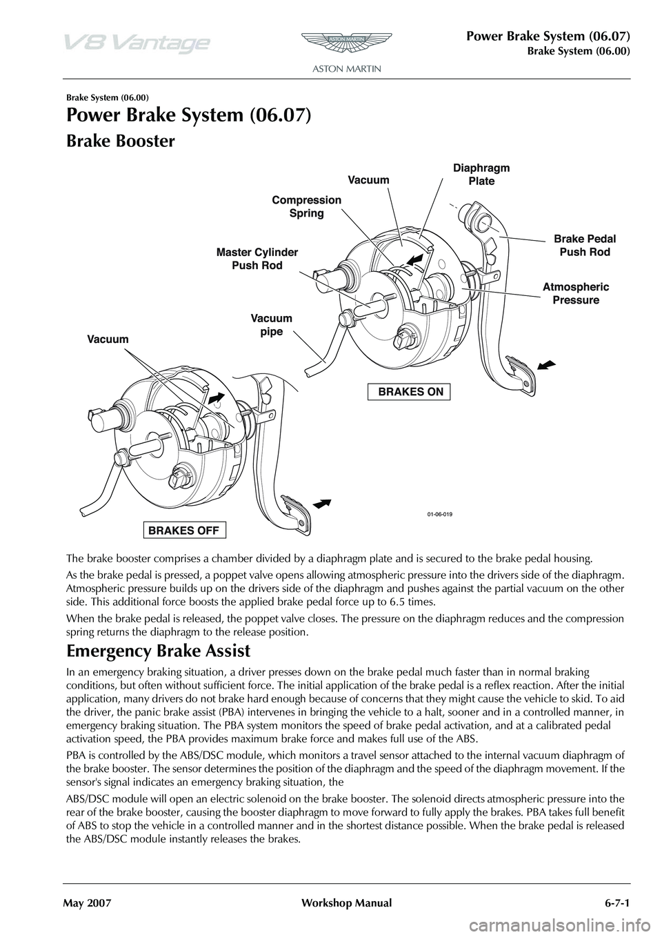
The brake booster comprises a chamber divided by a diap hragm plate and is secured to the brake pedal housing.
As the brake pedal is pressed, a poppet valve opens allowing at mospheric pressure into the drivers side of the diaphragm.
Atmospheric pressure builds up on the drivers side of the diaphragm and pushes against the partial vacuum on the other
side. This additional force boosts the a pplied brake pedal force up to 6.5 times.
When the brake pedal is released, the poppet valve closes. The pressure on the diaphragm reduces and the compression
spring returns the diaphragm to the release position.
Emergency Brake Assist
In an emergency braking situation, a driver presses down on the brake pedal much faster than in normal braking
conditions, but often without sufficient force. The initial appli cation of the brake pedal is a reflex reaction. After the initial
application, many drivers do not brake ha rd enough because of concerns that they might cause the vehicle to skid. To aid
the driver, the panic brake assist (PBA) intervenes in bringing the vehicle to a halt, sooner and in a controlled manner, in
emergency braking situation. The PBA system monitors the speed of brake pedal activation, and at a calibrated pedal
activation speed, the PBA provides maximum brake force and makes full use of the ABS.
PBA is controlled by the ABS/DSC module, which monitors a travel sensor attached to the internal vacuum diaphragm of
the brake booster. The sensor determines the position of th e diaphragm and the speed of the diaphragm movement. If the
sensor's signal indicates an emergency braking situation, the
ABS/DSC module will open an electric solenoid on the brake booster. The solenoid directs atmospheric pressure into the
rear of the brake booster, causing the booster diaphragm to mo ve forward to fully apply the brakes. PBA takes full benefit
of ABS to stop the vehicle in a controlled manner and in the shortest distance possible. When the brake pedal is released
the ABS/DSC module instantly releases the brakes.
Page 503 of 947

Power Brake System (06.07)
Brake System (06.00)
May 2007 Workshop Manual 6-7-3
Installation
1. Install booster assembly.
2. Connect brake pipes to master cylinder.
3. Install bolts (x2) clutch pipe bracket.
4. Connect clutch reservoir feed pipe.
5. Connect multiplugs (x4).
6. Install vacuum hose.
7. Install expansion tank asid e (bolt x1, nut x1, hose clips
x2, multiplug x1).
8. Install corner cross brace (torque) (only fully tighten
when vehicle on level floor).
9. Install servo retaining nuts (x4) (torque).
10. Install clevis pin and clip.
11. Bleed Brakes (see Workshop Manual procedure 06.06.AD Pad Kit - Manual Brake and Clutch Pedal -
Renew).
12. Top-up coolant.
Brake Fluid Reservoir-Renew
Removal
1. Remove corner cross brace.
2. Move expansion tank aside for access (bolt x1, nut x1, hose clips x2, multiplug x1).
3. Disconnect clutch reservoir feed pipe.
4. Disconnect multiplugs (x2). 5. Disconnect brake pipes from master cylinder (move
aside).
6. Remove reservoir holding screw for access to master cylinder retaining nut.
7. Remove master cylinder from booster (nuts x2).
8. Remove reservoir from master cylinder.
Installation
1. Fit new seals and install reservoir to master cylinder.
2. Install master cylinder to booster (nuts x2).
3. Install reservoir holding screw for access to master cylinder retaining nut
4. Connect brake pipes to master cylinder.
5. Connect clutch reservoir feed pipe.
6. Connect multiplugs (x2).
7. Install expansion tank aside (bolt x1, nut x1, hose clips x2, multiplug x1).
8. Install corner cross brace (torque) (only fully tighten
when vehicle on level floor).
9. Bleed Brakes (see Workshop Manual procedure 06.07.DD Brake Hydraulic System - Flush/Refill/Bleed).
10. Top-up coolant.
Brake Bleeding - AMDS
Use the AMDS to bleed the brakes if you are bleeding the
brake system after you replaced a major component, for
example: a modulator or a mast er cylinder or when filling
from empty.
If you are bleeding a caliper, you can use a manual brake-
bleed procedure.
1. Connect the AMDS.
Repair Operation Time (ROT)
Repair Operation Time (ROT)
Page 504 of 947

Power Brake System (06.07)
Brake System (06.00)6-7-4 Workshop Manual May 2007
2. Clean each caliper around the bleed screws. Remove the dust caps.
3. Prepare a bleed tube and a bottle that contains a small quantity of clean brake fluid.
4. If necessary, top up the brake fluid reservoir with brake fluid from a new container.
5. Switch on the AMDS and load the ‘Anti-lock braking diagnostics’ software.
6. Select ‘Brake Bleed’ and follow the AMDS instructions.
Brake Master Cylinder and Vacuum
Booster-Renew
Removal
1. Move drivers seat fully rearward.
2. Remove clevis pin and clip.
3. Remove booster securing nuts (x4).
4. Remove corner cross brace.
5. Move expansion tank aside for access (bolt x1, nut x1,
hose clips x2, multiplug x1).
6. Remove vacuum hose move aside.
7. Remove bolts (x2) from clutch pipe bracket and move aside.
8. Disconnect clutch reservoir feed pipe.
9. Disconnect multiplugs (x4).
10. Disconnect brake pipes from master cylinder (move aside).
11. Remove booster assembly.
Installation
1. Install booster assembly.
2. Connect brake pipes to master cylinder.
3. Install bolts (x2) clutch pipe bracket.
4. Connect clutch reservoir feed pipe.
5. Connect multiplugs (x4).
6. Install vacuum hose.
7. Install expansion tank aside (bolt x1, nut x1, hose clips x2, multiplug x1).
8. Install corner cross brace (torque) (only fully tighten when vehicle on level floor).
9. Install servo retaining nuts (x4) (torque).
10. Install clevis pin and clip.
11. Bleed Brakes (see Workshop Manual procedure 06.07.DD Brake Hydraulic System - Flush/Refill/Bleed).
WA R N I N G
BRAKE FLUID THAT CONTAINS WATER CAN AFFECT THE PERFORMANCE OF THE BRAKES AND CAUSE CORROSION IN THE BRAKE SYSTEM.
IF YOU KEEP BRAKE FLUID IN OPEN CONTAINERS, IT WILL ABSORB WATER VAPOUR.
USE ONLY BRAKE FLUID FROM NEW CONTAINERS
WHEN YOU TOP-UP THE BRAKE FLUID RESERVOIR..
When you bleed a brake caliper, always bleed the inner bleed screw first, followed by the outer bleed screw, then bleed the inne r bleed screw again.
Repair Operation Time (ROT)
WAR NI NG
AVOID SKIN / EYE CONTACT OR INGESTION OF
BRAKE FLUID. IF SKIN OR EYES ARE SPLASHED WITH BRAKE FLUID, RINSE THE AFFECTED AREA
IMMEDIATELY WITH PLENTY OF WATER AND OBTAIN
MEDICAL ATTENTION. IF BR AKE FLUID IS INGESTED,
OBTAIN IMMEDIATE MEDICAL ATTENTION.
WAR NI NG
BRAKE FLUID IS HYGROSCOPIC. IF KEPT IN OPENED CONTAINERS IT WILL ABSORB WATER VAPOUR. USE ONLY BRAKE FLUID FROM FRESHLY OPENED
CONTAINERS WHEN TOPPING-UP THE BRAKE FLUID RESERVOIR.
Caution
Brake fluid must not be allowed to contact the vehicle
paint work. Remove spilt brake fluid from the paint work
by rinsing away with running water.
Caution
Always plug pipe ends to prevent ingress of dirt or
moisture into the system.
Caution
Always plug pipe ends to prevent ingress of dirt or
moisture into the system.
Page 505 of 947

Power Brake System (06.07)
Brake System (06.00)
May 2007 Workshop Manual 6-7-5
12. Top-up coolant.
Brake Master Cylinder-Renew
Removal
1. Remove corner cross brace.
2. Move expansion tank aside for access (bolt x1, nut x1, hose clips x2, multiplug x1).
3. Disconnect clutch reservoir feed pipe.
4. Disconnect multiplugs (x2).
5. Disconnect brake pipes from master cylinder (move aside).
6. Remove reservoir holding screw for access to master cylinder retaining nut.
7. Remove master cylinder from booster (nuts x2).
Installation
1. On new master cylinder - Remove reservoir holding screw for access to master cylinder retaining nut
2. Install master cylinder to booster (nuts x2).
3. Install reservoir holding screw for access to master cylinder retaining nut
4. Connect brake pipes to master cylinder.
5. Connect clutch reservoir feed pipe.
6. Connect multiplugs (x2).
7. Install expansion tank asid e (bolt x1, nut x1, hose clips
x2, multiplug x1). 8. Install corner cross brace
(torque) (only fully tighten
when vehicle on level floor).
9. Bleed Brakes (see Workshop Manual procedure 006.07.DD Brake Hydraulic System - Flush/Refill/
Bleed).
10. Top-up coolant.
Repair Operation Time (ROT)
Page 507 of 947

Anti-lock Braking System (ABS) (06.09)
Brake system (06.00)
Issue 4, November 2008 Workshop Manual 6-9-1
Brake system (06.00)
Anti-lock Braking System (ABS) (06.09)
The anti-lock braking system (ABS) is a four-channel system
having independent inputs from all four-wheel speed
sensors.
The ABS module, monitors signals from the sensors to
calculate, brake slip and the acceleration / deceleration of
individual wheels. When the brake pedal is depressed, and
the ABS module detects incipient wheel lock-up from the
incoming signals, it triggers the re-circulation pump inside
the module’s hydraulic modulator, and the solenoid valves
for the wheel(s) concerned. Brake pressure, is then
modulated to increase / decrease or remain constant at the
wheel(s) concerned until whee l lock-up is eliminated. The
ABS provides self-diagnosis and any malfunction within the
system will be indicated to the dr iver by the illumination of
the brake warning light and ‘ABS FAULT’ displayed in the
message centre right. Should a fault develop within the ABS,
the brake system will operate conventionally and with the
same standard of performanc e as a vehicle not equipped
with ABS.
Dynamic Stability Control
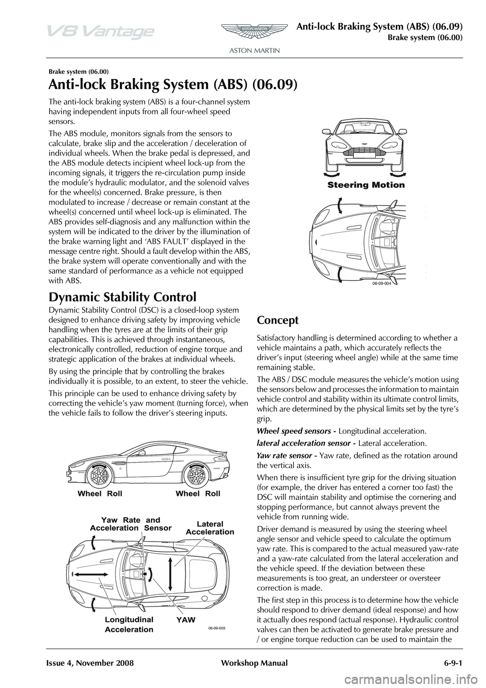
Dynamic Stability Control (DSC ) is a closed-loop system
designed to enhance driving safety by improving vehicle
handling when the tyres are at the limits of their grip
capabilities. This is achieved through instantaneous,
electronically controlled, reduction of engine torque and
strategic application of the brakes at individual wheels.
By using the principle that by controlling the brakes
individually it is possible, to an extent, to steer the vehicle.
This principle can be used to enhance driving safety by
correcting the vehicle’s yaw moment (turning force), when
the vehicle fails to follow th e driver’s steering inputs.
Concept
Satisfactory handling is determined according to whether a
vehicle maintains a path, wh ich accurately reflects the
driver
Page 602 of 947

Steering Gear (11.01)
Steering (11.00)
Issue 5, January 2010 Workshop Manual 11-1-3
Vehicle tends to pull
to one side when
driven on a level
surface. Incorrect tyre pressure. Adjust tyre pressure.
Incorrect tyre size.
Different tyre or tread type.
New tyre as required.
Vehicle is unevenly or excessively loaded. Adjust load evenly.
Incorrect toe adjustment. Adjust as required.
Damaged front or rear suspension
components. New suspension components.
Steering gear valve effort out of balance. Shift transmission into neutral while driving at no more than 30 miles/hour (50 km/h) and turn the
ignition to position I (engine ‘Off’-coasting).
a. If the vehicle does not pull to one side with the
engine off, install a new steering gear.
b. If the vehicle drifts with the engine off, ‘cross switch’ the front wheel assemblies.
Test at low speed due to directional tyres.
a. If the vehicle pulls to the opposite side, switch the wheels that were on the rear to the same
side on the front.
b. If the vehicle pull direction is not changed, check the front suspension components and
toe adjustments.
Check front and rear brakes for correct
operation. Adjust as required.
Check for bent rear suspension components
and for damaged coil springs in the front
suspension. New rear suspension components.
Check the rear suspension for loose or worn
suspension components. Tighten.
New components.
Incorrect underbody alignment. Check underbody alignment.
Feedback (whining
or knocking noises
in the steering gear)
Condition where
roughness is felt in
the steering wheel by
the driver when the
vehicle is driven over
rough surfaces. Loose or worn tie-rods. New steering gear.
Steering gear bolts loose or damaged. Tighten.
New bolts.
Loose suspension bushing , bolts or ball joints. Tighten.
New components.
Damaged steering column.
Loose Column bolts. New steering column.
Tighten bolts.
Power steering
pump or reservoir
leaks Overfilled system. Correct fluid level.
Damaged fluid cap. New fluid cap.
Loose or damaged hose fittings. Tighten.
New hose.
Leakage at power steering pump. New power steering pump.
Poor returnability of
the steering Incorrect tyre pressure. Check
and adjust tyre pressure.
Incorrect tyre size or ty pe. New tyre as required.
Steering column universal joints binding . New steering column.
Steering column shaft floor seal may be torn
and fouling I-shaft. New floor seal as required.
Binding or damaged tie-rods. New steering gear.
Damaged or worn front suspension
components. New front suspension components as required.
Incorrect toe adjustment. Adjust as required.
SymptomPossible CauseAction