brakes ASTON MARTIN V8 VANTAGE 2010 Workshop Manual
[x] Cancel search | Manufacturer: ASTON MARTIN, Model Year: 2010, Model line: V8 VANTAGE, Model: ASTON MARTIN V8 VANTAGE 2010Pages: 947, PDF Size: 43.21 MB
Page 3 of 947
Contents
Issue 5, January 2010 Workshop Manual 0-0-3
V8 Vantage Workshop Manual
Contents
IntroductionWelcome .............................................................. 0-0-6
Safety Precautions ................................................. 0-0-7
Lifting and Jacking ................................................. 0-0-9
Vehicle Recovery ................................................ 0-0-10
Vehicle Identification Number ............................ 0-0-11
Body System (01.00) Body Structure (01.01) .......................................... 1-1-4
Front End System (01.02) ...................................... 1-2-1
Body Closures (01.03) ........................................... 1-3-1
Interior Trim (01.05) ............................................. 1-4-1
Exterior Trim (01.08) ............................................. 1-8-1
Mirrors (01.09) ...................................................... 1-9-1
Seating (01.10).................................................... 1-10-1
Glass, Frame and Mechanism (01.11) .................. 1-11-1
Instrument Panel (IP) (01.12) . .............................. 1-12-1
Handles and Lock Mechanisms (01.14) ............... 1-14-1
Wipers and Washer System (01.16)..................... 1-16-1
Convertible Roof and Roof Opening
Subsystem (01.17)................ ...............................1-17-1
Bumpers (01.19) ................................................. 1-19-1
Restraining Devices (01.20) .... ............................. 1-20-1
Frame and Mounting (02.00) Subframes (02.03) ................................................. 2-1-2
Engine System (03.00) Engine Assembly....................................................3-0-3
Engine Structure (03.01)........................................ 3-1-1
Lubrication System (03.02).................................... 3-2-1
Cooling System (03.03) ......................................... 3-3-1
Fuel Charging System (03.04) ................................ 3-4-1
Accessory Drive System (03.05)............................. 3-5-1
Engine Cranking System (03. 06) ............................ 3-6-1
Valve Train (03.09) ............................................... 3-9-1
Engine Sealing (03.10)......................................... 3-10-1
Power Conversion (03.11)................................... 3-11-1
Evaporative Emissions (03.13) ............................. 3-11-1
Engine Management System (0 3.14).................... 3-14-1
Throttle Control (03.16) ...... ................................ 3-16-1
Foot Operated Control (03.18)............................ 3-18-1
Suspension (04.00) Road Wheel Alignment (04.00) ............................. 4-0-2
Front Suspension (04.01)....................................... 4-1-1
Rear Suspension (04.02)........................................ 4-2-1
Shock Absorber System (04.03) ............................. 4-3-1
Road Wheels and Tyres (04.04) ............................ 4-4-1
Driveline (05.00) Driveshaft (05.01) ................................................. 5-1-2
Halfshafts (05.05) .................................................. 5-2-1 Brake System (06.00)
Front Disc Brake (06.03) ....................................... 6-3-2
Rear Disc Brakes (06.04) ....................................... 6-4-1
Hand Brake (06.05) .............................................. 6-5-1
Brake Actuation System (06.06 ) ............................ 6-6-1
Power Brake System (06.07) ................................. 6-7-1
Anti-lock Braking System (06.09)........................... 6-9-1
Transmission (07.00) Transmission Cooling (07.02) ................................ 7-0-2
Manual Transmission (07.03) ................................ 7-3-1
Automatic Control System (07.05)......................... 7-5-1
Manual Control System (07.06) ............................. 7-6-1
Automatic Shifting Subsytem (07.11) .................. 7-11-1
Clutch (08.00) Clutch Controls (08.02) ......................................... 8-1-2
Exhaust (09.00) Exhaust Overview ................................................. 9-1-2
Silencer Assembly (09.01) ..................................... 9-1-3
Pipes and Supports (09.03) ................................... 9-2-1
Exhaust Protection (09.04) .................................... 9-3-1
Fuel (10.00) Fuel Tank and Lines (10.01) ................................ 10-1-2
Steering (11.00) Steering Gear (11.01) .......................................... 11-1-2
Power Steering (11.02)........................................ 11-2-1
Steering Column (11.04) ..................................... 11-4-1
Steering Column Switches (1 1.05) ....................... 11-5-1
Steering Wheel (11.06) ....................................... 11-6-1
Climate Control (12.00) Body Ventilation system (12.01) .......................... 12-1-2
Heater System (12.02) ........................................ 12-2-1
Air Conditioning (A/C) System (12.03) ................. 12-3-1
Information, Gauge and Warning (13.00) Instrument Cluster (13.01) .................................. 13-1-2
Power Supply (14.00) Battery System (14.01) ........................................ 14-1-2
Alternator and Regulator System (14.02) ............. 14-2-1
Vehicle Entertainment (15.00) Audio System (15.01)................................ ..........15-1-2
Antenna (15.02).................................................. 15-2-1
Vacuum Distribution (16.00) Body Vacuum System (16.01) ............................. 16-1-2
Lighting (17.00) Front Lights (17.01) ............................................. 17-1-2
Interior Lighting (17.02) ...................................... 17-2-1
Rear Lights (17.03) .............................................. 17-3-1
Lighting Mechanisms (17.04). .............................. 17-4-1
Page 10 of 947
Vehicle Recovery
0-0-10 Workshop Manual Issue 5, January 2010
Vehicle Recovery
General
Preferred method of vehicle recovery is by flat bed
transporter.
The towing eye is primarily for emergency use when towing
for short distances, e.g. removing vehicle if it is causing an
obstruction or winching vehicl e onto a flatbed transporter.
If moving this vehicle in such a situation, install the towing
eye to the bracket in the lower grille aperture.
Transporting
If vehicle is to be transported on a trailer or flat bed
transporter the handbrake must be applied and the road
wheels must be chocked.
Suspended Towing
Take care when using 'spectacle frame' type towing
equipment that the towing device is well clear of front or
rear apron. Body damage may occur if vehicle passes over
uneven road surfaces.
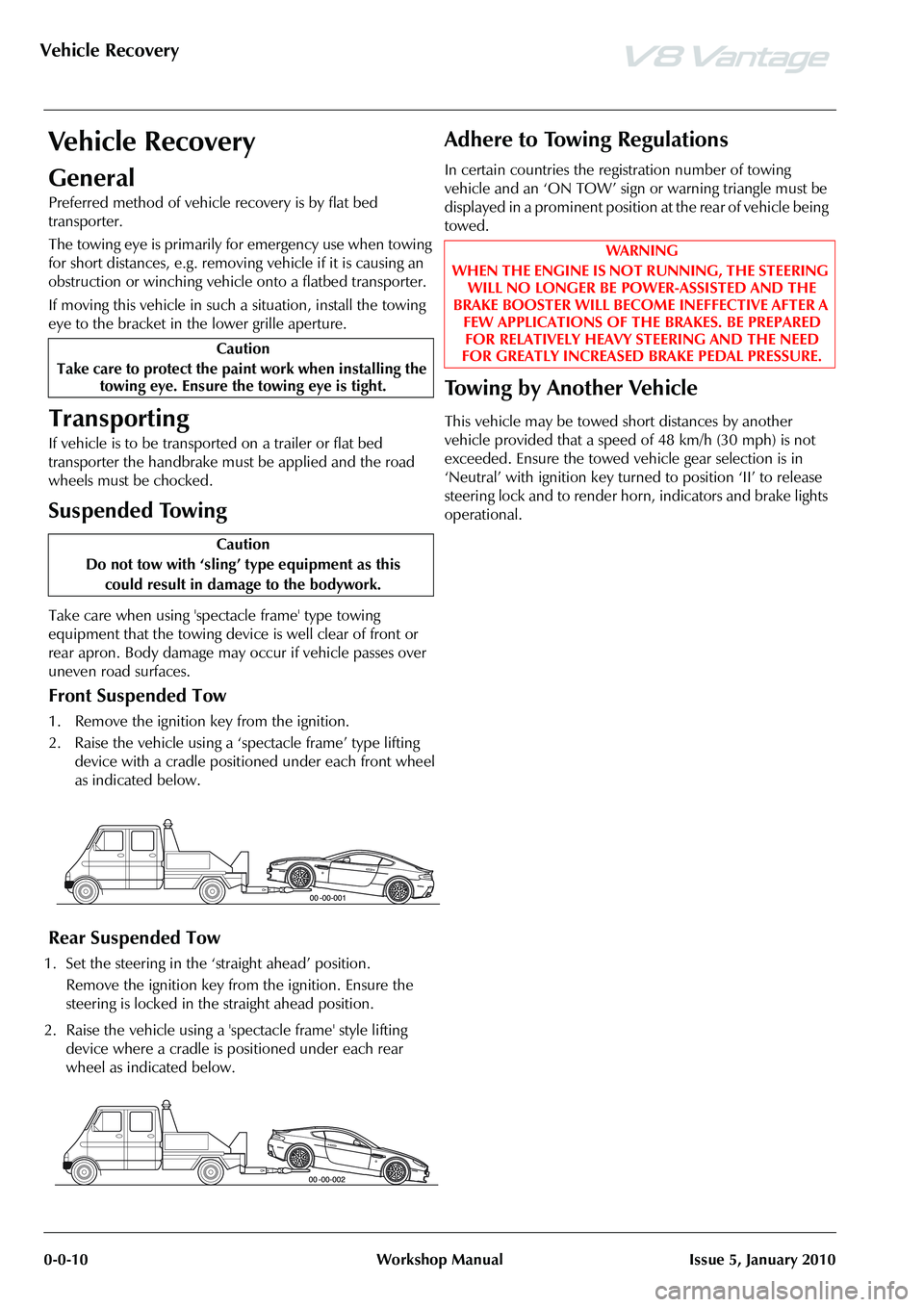
Front Suspended Tow
1. Remove the ignition key from the ignition.
2. Raise the vehicle using a ‘spectacle frame’ type lifting device with a cradle positioned under each front wheel
as indicated below.
Rear Suspended Tow
1. Set the steering in the ‘straight ahead’ position.
Remove the ignition key from the ignition. Ensure the
steering is locked in the straight ahead position.
2. Raise the vehicle using a 'spectacle frame' style lifting device where a cradle is positioned under each rear
wheel as indicated below.
Adhere to Towing Regulations
In certain countries the regi stration number of towing
vehicle and an ‘ON TOW’ sign or warning triangle must be
displayed in a prominent position at the rear of vehicle being
towed.
To w i n g b y A n o t h e r V e h i c l e
This vehicle may be towed short distances by another
vehicle provided that a speed of 48 km/h (30 mph) is not
exceeded. Ensure the towed vehicle gear selection is in
‘Neutral’ with ignition key turned to position ‘II’ to release
steering lock and to render hor n, indicators and brake lights
operational.
Caution
Take care to protect the paint work when installing the towing eye. Ensure the towing eye is tight.
Caution
Do not tow with ‘sling’ type equipment as this
could result in damage to the bodywork.
WAR NI NG
WHEN THE ENGINE IS NOT RUNNING, THE STEERING WILL NO LONGER BE POWER-ASSISTED AND THE
BRAKE BOOSTER WILL BECOME INEFFECTIVE AFTER A FEW APPLICATIONS OF TH E BRAKES. BE PREPARED
FOR RELATIVELY HEAVY STEERING AND THE NEED
FOR GREATLY INCREASED BRAKE PEDAL PRESSURE.
Page 428 of 947

Front Suspension (04.01)
Suspension (04.00)4-1-2 Workshop Manual November 2008
Symptoms
SymptomPossible CauseAction
Crabbing Front or rear suspension components/road
wheel alignment Inspect front and rear suspension systems.
Check / adjust road wheel alignment
Drive axle damaged New drive axle.
Front ‘Bottoming’
or Riding Low Spring(s)
Dampers Check ride height.
Check dampers.
Drift/Pull Unequal tyre pressure Check / adjust tyre pressures.
Inspect tyre for excessive wear.
Incorrect road wheel alignment Check / adjust road wheel alignment.
Tyres Check / adjust tyre pressu res. Inspect tyre for excessive
wear.
Unevenly loaded or overloaded vehicle Not ify customer of incorrect vehicle loading .
Damaged steering components Check steering sy stem for mechanical or hydraulic bias.
Brake drag Check brakes.
Check steering system for mechanical or hydraulic bias.
Rough Ride Spring(s) Check springs.
Shock absorber(s) Check shock absorbers.
Incorrect Tyre
Wear Incorrect tyre pressure Check and adju
st tyre pressure. Inspect tyre for
excessive wear.
Excessive front or rear Toe (rapid inner or
outer edge wear) Check and adjust road wheel alignment (Refer to ’Road
Wheel Alignment (04.00)’, page 4-0-2).
Excessive negative or positive camber
(rapid or outer edge wear) Check and adjust road wheel alignment (Refer to ’Road
Wheel Alignment (04.00)’, page 4-0-2).
Tyres out of balance (tyres cupped or
dished) Balance tyres.
‘Shimmy’ or ‘Road
Wheel Tramp’ Loose road wheel nut(s) Check and tighten road wheel nuts to specification.
Loose front suspension Check and tighten
suspension fixings to specification.
Front road wheel bearing(s) Check road wheel bearings.
Road wheel / tyres Check road wheels / tyres.
Shock absorber(s) Check shock absorbers.
Spring(s) Check springs.
Loose, worn or damaged ball -joint(s) Check ball-joint(s).
Loose, worn or damaged steering
components Check components.
Front road wheel alignment Check and adjust road wheel alignment (Refer to ’Road Wheel Alignment (04.00)’, page 4-0-2).
Worn or damaged suspension bushes Check suspension bushes
Poor ‘Return
ability’ of Steering ball-joints Check ball-joint(s).
Steering components Check for excessive friction in steering system.
Check tyre pressures
Steering Wheel
Off-Centre Unequal front or rear Toe settings Check and adjust road wheel alignment.
Steering components Check and install new components as required.
Sway or Roll Overloaded, unevenly or incorrectly
loaded vehicle Notify customer of incorrect vehicle loading
Loose road wheel nut(s) Check. Tighten road wheel nut(s) to specification
Spring(s) Check. Install new springs as required.
Shock absorber(s) Check. Install new shock absorbers as required.
Loose front stabilizer bar or rear stabilizer
bar Check. Tighten anti-roll bar to specification.
Page 473 of 947
Version 6, March 2010 Workshop Manual 6-3-1
Brake System (06.00)
Contents
Front Disc Brake (06.03)........................................ 6-3-2Description ............................................................. 3-2
Specifications.......................................................... 3-2
Maintenance ........................................................... 3-3Front Brake Disc Set - Renew ................................. 3-3
Front Caliper-Renew .............................................. 3-4
Front Pad Kit - Renew ............................................ 3-5
Front Brake Hose Assembly - Renew ...................... 3-5
Rear Disc Brakes (06.04) ....................................... 6-4-1 Description ............................................................. 4-1
Specifications.......................................................... 4-1
Maintenance ........................................................... 4-2Rear Brake Disc Set-Renew .................................... 4-2
RH/LH Rear Caliper-Renew ................................... 4-2
Rear Pad Kit-Renew ............................................... 4-3
Rear Brake Hose Assembly-Renew ......................... 4-4
Hand Brake (06.05) ................ ............................... 6-5-1
Description ............................................................. 5-1
Specifications.......................................................... 5-1
Maintenance ........................................................... 5-2 RH/LH Handbrake Caliper-Re new ......................... 5-2
Handbrake Lever Assembly-Renew ........................ 5-2
Handbrake Pad Set-Renew .................................... 5-2
Handbrake Cable Assembly-Adjust......................... 5-3
Handbrake Cable Assembly-Vehicle Set-Renew ..... 5-3
Brake Actuation System (06.06)............................. 6-6-1 Description ............................................................. 6-1
Tandem Master Cylinder ........................................ 6-1
Specifications.......................................................... 6-1
Maintenance ........................................................... 6-2Pedal Box Assembly - Renew ................................. 6-2
Installation ............................................................. 6-2
RHD-Brake Master Cylinder Assembly-Renew........ 6-2
LHD-Brake Master Cylinder Assembly-Renew ........ 6-3
Clutch Master Cylinder Assembly-Renew ............... 6-3
RH/LH Front Caliper Hose Assembly-Renew .......... 6-4
RH/LH Rear Brake Caliper Tube Assembly-Renew . 6-5
Brake Master Cylinder to Modulator Secondary
Tube Assembly-Renew ........................................... 6-6
Brake Master Cylinder to Modulator Primary
Tube Assembly-Renew ........................................... 6-7
Rear Wheel Brake Front to Rear Tube Assembly
-Renew .................................................................. 6-8
RH Front Caliper to Modulator Tube Assembly
-Renew .................................................................. 6-9
Rear Wheel Brake Tube Assembly-Renew ............ 6-10
Dynamic Stability Control Module-Renew............ 6-11
Power Brake System (06.07) .................................. 6-7-1 Brake Booster ......................................................... 7-1
Emergency Brake Assist .......................................... 7-1
Specifications.......................................................... 7-2
Maintenance ........................................................... 7-2Brake Booster-RHD-Renew.................................... 7-2
Brake Booster-LHD-Renew .................................... 7-2 Brake Fluid Reservoir-Renew ................................. 7-3
Brake Bleeding - AMDS ......................................... 7-3
Brake Master Cylinder and Vacuum Booster
-Renew .................................................................. 7-4
Brake Master Cylinder-Renew ................................ 7-5
Anti-lock Braking System (ABS) (06.09)................. 6-9-1 Dynamic Stability Control ...................................... 9-1Concept ................................................................ 9-1
System Overview ................................................... 9-2
Operation Summary .............................................. 9-2
Traction Control ..................................................... 9-2 Functional Description ........................................... 9-2
Engine Intervention ................................................ 9-3
Brake Intervention ................................................. 9-3
ABS / DSC Circuit .................................................. 9-3
Specifications ......................................................... 9-3 Maintenance ......................................................... 9-4
ABS Modulator - Remove and Install ...................... 9-4
Page 479 of 947
Rear Disc Brakes (06.04)
Brake system (06.00)
May 2007 Workshop Manual 6-4-1
Brake system (06.00)
Rear Disc Brakes (06.04)
Description
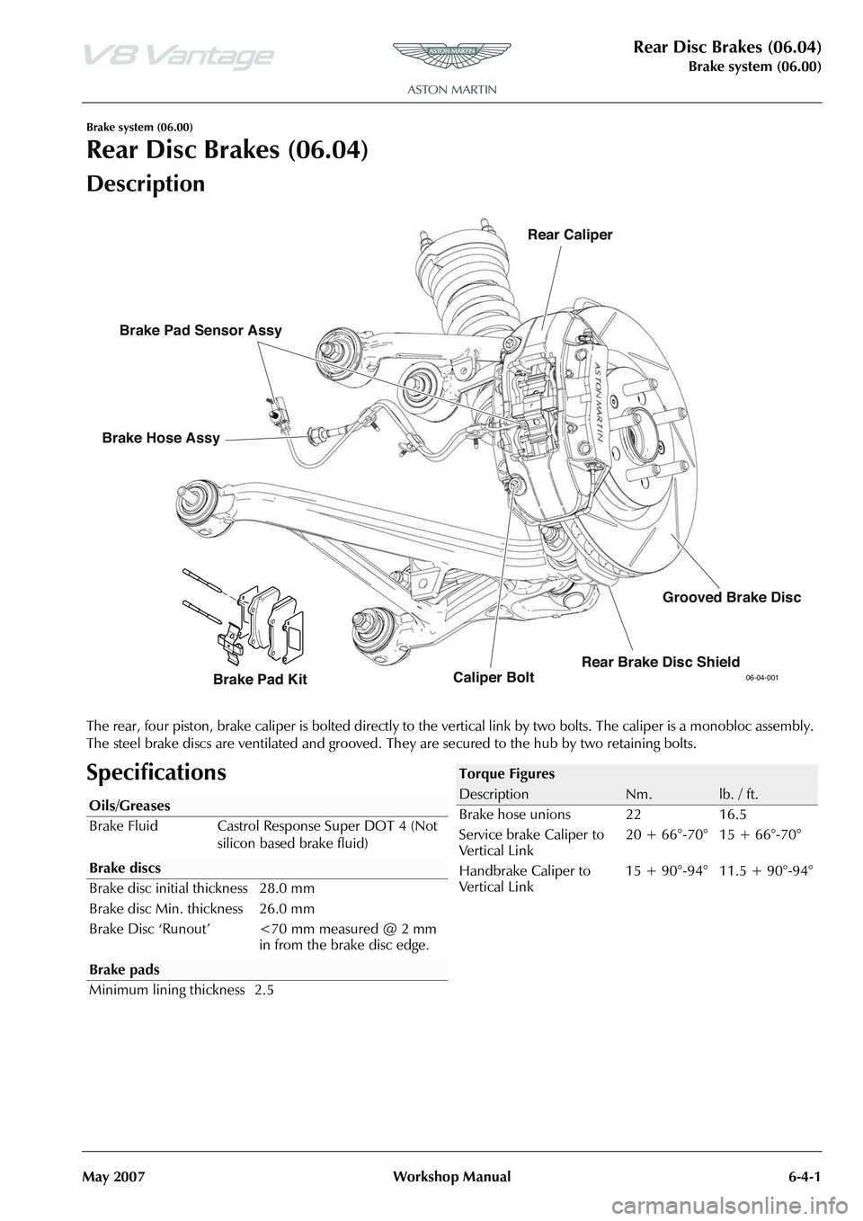
The rear, four piston, brake caliper is bolted directly to the ve rtical link by two bolts. The caliper is a monobloc assembly.
The steel brake discs are ventilated and grooved. Th ey are secured to the hub by two retaining bolts.
Specifications
06-04-001Caliper BoltRear Caliper
Brake Hose Assy
Brake Pad Kit
Brake Pad Sensor Assy
Rear Brake Disc ShieldGrooved Brake Disc
Oils/Greases
Brake Fluid Castrol Response Super DOT 4 (Not
silicon based brake fluid)
Brake pads
Minimum lining thickness 2.5
Torque Figures
DescriptionNm.lb. / ft.
Brake hose unions 22 16.5
Service brake Caliper to
Vertical Link 20 + 66°-70° 15 + 66°-70°
Handbrake Caliper to
Vertical Link 15 + 90°-94° 11.5 + 90°-94°
Page 480 of 947
Rear Disc Brakes (06.04)
Brake system (06.00)6-4-2 Workshop Manual May 2007
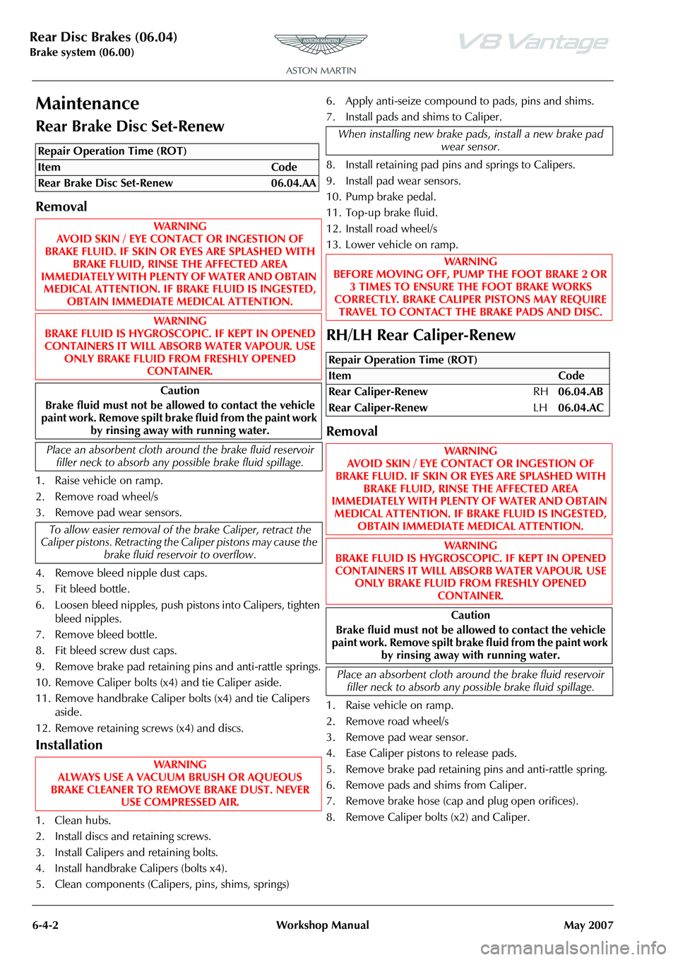
Maintenance
Rear Brake Disc Set-Renew
Removal
1. Raise vehicle on ramp.
2. Remove road wheel/s
3. Remove pad wear sensors.
4. Remove bleed nipple dust caps.
5. Fit bleed bottle.
6. Loosen bleed nipples, push pistons into Calipers, tighten bleed nipples.
7. Remove bleed bottle.
8. Fit bleed screw dust caps.
9. Remove brake pad retaining pins and anti-rattle springs.
10. Remove Caliper bolts (x4) and tie Caliper aside.
11. Remove handbrake Caliper bolts (x4) and tie Calipers aside.
12. Remove retaining screws (x4) and discs.
Installation
1. Clean hubs.
2. Install discs and retaining screws.
3. Install Calipers and retaining bolts.
4. Install handbrake Ca lipers (bolts x4).
5. Clean components (Caliper s, pins, shims, springs)6. Apply anti-seize compound to pads, pins and shims.
7. Install pads and shims to Caliper.
8. Install retaining pad pins
and springs to Calipers.
9. Install pad wear sensors.
10. Pump brake pedal.
11. Top-up brake fluid.
12. Install road wheel/s
13. Lower vehicle on ramp.
RH/LH Rear Caliper-Renew
Removal
1. Raise vehicle on ramp.
2. Remove road wheel/s
3. Remove pad wear sensor.
4. Ease Caliper pistons to release pads.
5. Remove brake pad retaining pins and anti-rattle spring.
6. Remove pads and shims from Caliper.
7. Remove brake hose (cap and plug open orifices).
8. Remove Caliper bolts (x2) and Caliper.
Repair Operation Time (ROT)
When installing new brake pads, install a new brake pad wear sensor.
WAR NI NG
BEFORE MOVING OFF, PUMP THE FOOT BRAKE 2 OR
3 TIMES TO ENSURE THE FOOT BRAKE WORKS
CORRECTLY. BRAKE CALIPER PISTONS MAY REQUIRE TRAVEL TO CONTACT THE BRAKE PADS AND DISC.
Repair Operation Time (ROT)
ItemCode
Rear Caliper-Renew RH06.04.AB
Rear Caliper-Renew LH06.04.AC
WAR NI NG
AVOID SKIN / EYE CONTACT OR INGESTION OF
BRAKE FLUID. IF SKIN OR EYES ARE SPLASHED WITH BRAKE FLUID, RINSE THE AFFECTED AREA
IMMEDIATELY WITH PLENTY OF WATER AND OBTAIN
MEDICAL ATTENTION. IF BR AKE FLUID IS INGESTED,
OBTAIN IMMEDIATE MEDICAL ATTENTION.
WAR NI NG
BRAKE FLUID IS HYGROSCOPIC. IF KEPT IN OPENED CONTAINERS IT WILL ABSORB WATER VAPOUR. USE ONLY BRAKE FLUID FROM FRESHLY OPENED
CONTAINER.
Caution
Brake fluid must not be allowed to contact the vehicle
paint work. Remove spilt brake fluid from the paint work
by rinsing away with running water.
Place an absorbent cloth around the brake fluid reservoir filler neck to absorb any possible brake fluid spillage.
Page 481 of 947
Rear Disc Brakes (06.04)
Brake system (06.00)
May 2007 Workshop Manual 6-4-3
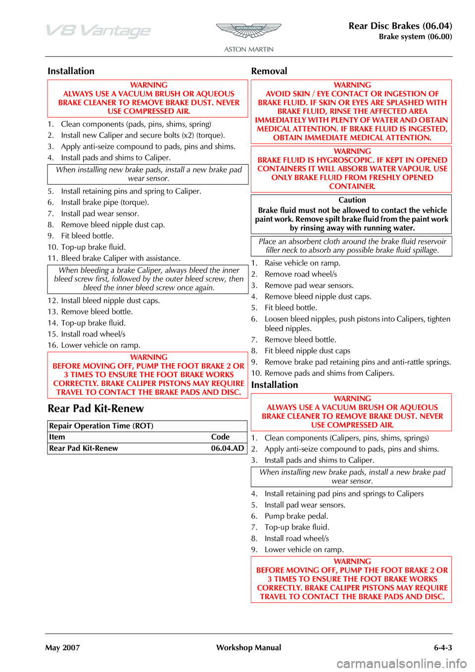
Installation
1. Clean components (pads, pins, shims, spring)
2. Install new Caliper and secure bolts (x2) (torque).
3. Apply anti-seize compound to pads, pins and shims.
4. Install pads and shims to Caliper.
5. Install retaining pins and spring to Caliper.
6. Install brake pipe (torque).
7. Install pad wear sensor.
8. Remove bleed nipple dust cap.
9. Fit bleed bottle.
10. Top-up brake fluid.
11. Bleed brake Calipe r with assistance.
12. Install bleed nipple dust caps.
13. Remove bleed bottle.
14. Top-up brake fluid.
15. Install road wheel/s
16. Lower vehicle on ramp.
Rear Pad Kit-Renew
Removal
1. Raise vehicle on ramp.
2. Remove road wheel/s
3. Remove pad wear sensors.
4. Remove bleed nipple dust caps.
5. Fit bleed bottle.
6. Loosen bleed nipples, push pistons into Calipers, tighten bleed nipples.
7. Remove bleed bottle.
8. Fit bleed nipple dust caps
9. Remove brake pad retaining pins and anti-rattle springs.
10. Remove pads and shims from Calipers.
Installation
1. Clean components (Caliper s, pins, shims, springs)
2. Apply anti-seize compound to pads, pins and shims.
3. Install pads and shims to Caliper.
4. Install retaining pad pins and springs to Calipers
5. Install pad wear sensors.
6. Pump brake pedal.
7. Top-up brake fluid.
8. Install road wheel/s
9. Lower vehicle on ramp.
WA R N I N G
ALWAYS USE A VACUUM BRUSH OR AQUEOUS
BRAKE CLEANER TO REMOVE BRAKE DUST. NEVER USE COMPRESSED AIR.
When installing new brake pads, install a new brake pad wear sensor.
When bleeding a brake Calipe r, always bleed the inner
bleed screw first, followed by the outer bleed screw, then
bleed the inner bleed screw once again.
WA R N I N G
BEFORE MOVING OFF, PUMP THE FOOT BRAKE 2 OR 3 TIMES TO ENSURE THE FOOT BRAKE WORKS
CORRECTLY. BRAKE CALIPER PISTONS MAY REQUIRE TRAVEL TO CONTACT THE BRAKE PADS AND DISC.
Repair Operation Time (ROT)
WA R N I N G
AVOID SKIN / EYE CONTACT OR INGESTION OF
BRAKE FLUID. IF SKIN OR EYES ARE SPLASHED WITH BRAKE FLUID, RINSE THE AFFECTED AREA
IMMEDIATELY WITH PLENTY OF WATER AND OBTAIN
MEDICAL ATTENTION. IF BRAKE FLUID IS INGESTED, OBTAIN IMMEDIATE MEDICAL ATTENTION.
WA R N I N G
BRAKE FLUID IS HYGROSCOPI C. IF KEPT IN OPENED
CONTAINERS IT WILL ABSORB WATER VAPOUR. USE ONLY BRAKE FLUID FROM FRESHLY OPENED
CONTAINER.
Caution
Brake fluid must not be allo wed to contact the vehicle
paint work. Remove spilt brake fluid from the paint work by rinsing away with running water.
Place an absorbent cloth arou nd the brake fluid reservoir
filler neck to absorb any po ssible brake fluid spillage.
WA R N I N G
ALWAYS USE A VACUUM BRUSH OR AQUEOUS
BRAKE CLEANER TO REMOVE BRAKE DUST. NEVER USE COMPRESSED AIR.
When installing new brake pa ds, install a new brake pad
wear sensor.
WA R N I N G
BEFORE MOVING OFF, PUMP THE FOOT BRAKE 2 OR 3 TIMES TO ENSURE THE FOOT BRAKE WORKS
CORRECTLY. BRAKE CALIPER PISTONS MAY REQUIRE
TRAVEL TO CONTACT THE BRAKE PADS AND DISC.
Page 482 of 947

Rear Disc Brakes (06.04)
Brake system (06.00)6-4-4 Workshop Manual May 2007
Rear Brake Hose Assembly-Renew
Removal
1. Raise vehicle on ramp.
2. Remove road wheel/s
3. Remove bleed nipple dust caps.
4. Fit bleed bottle to RHR/LHR Caliper, open bleed nipples (x1).
5. Fit bleed bottle to RHF/LHF Caliper, open bleed nipples (x1).
6. Depress brake pedal >60 mm and secure with support.
7. Tighten RHF/LHR bleed nipple, remove bleed bottle and fit dust cap.
8. Tighten RHR/LHR bleed nipple, remove bleed bottle.
9. Remove clips (x3) wear indicator harness to brake hose.
10. Remove brake hose from Ca liper (cap and plug open
orifices).
11. Remove brake union from hose.
12. Remove hose C-clip and remove hose.
Installation
1. Install hose C-clip and hose.
2. Install brake union to hose (torque).
3. Install brake pipe to Cali per (torque) using alignment
tool (206-100).
4. Remove pedal support.
5. Top-up brake fluid.
6. Bleed brake Caliper with assistance. 7. Remove bleed bottle.
8. Fit bleed nipple dust caps.
9. Clean off excess fluid.
10. Top-up brake fluid.
11. Install road wheel/s
12. Lower vehicle on ramp.
Repair Operation Time (ROT)
Page 483 of 947
Hand Brake (06.05)
Brake Systems (06.00)
May 2007 Workshop Manual 6-5-1
Brake Systems (06.00)
Hand Brake (06.05)
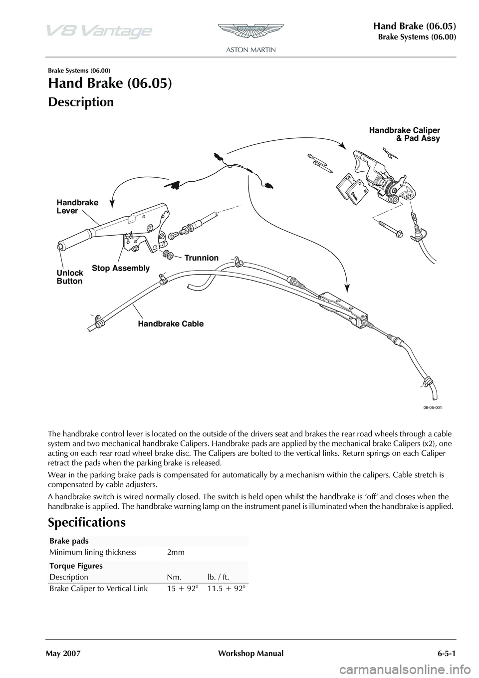
Description
The handbrake control lever is located on the outside of the drivers seat and brakes the rear road wheels through a cable
system and two mechanical handbrake Calipers. Handbrake pads are applied by the mechanical brake Calipers (x2), one
acting on each rear road wheel brake disc. The Calipers are bo lted to the vertical links. Return springs on each Caliper
retract the pads when the parking brake is released.
Wear in the parking brake pads is compensated for automati cally by a mechanism within the calipers. Cable stretch is
compensated by cable adjusters.
A handbrake switch is wired normally closed. The switch is he ld open whilst the handbrake is ‘off’ and closes when the
handbrake is applied. The handbrake warning lamp on the instrument panel is illuminated when the handbrake is applied.
Specifications
06-05-001
Unlock
Button
Handbrake
Lever
Trunnion
Handbrake Cable
Stop Assembly
Handbrake Caliper
& Pad Assy
Brake pads
Minimum lining thickness 2mm
Torque Figures
DescriptionNm.lb. / ft.
Brake Caliper to Vertical Link 15 + 92° 11.5 + 92°
Page 486 of 947

Hand Brake (06.05)
Brake Systems (06.00)6-5-4 Workshop Manual May 2007
12. Remove cable from subframe.
Installation
1. Install cable into body.
2. Connect cable to handbrake lever and install handbrake lever (see Workshop Manual procedure 06.05.CB
Handbrake Lever Assembly - Renew).
3. Clip cable in cabin
4. Install cable to subframe (bolts x4).
5. Install heat shield bolts (x4) and clips (x2).
6. Install exhaust rear silencer box (see Workshop Manual procedure 09.00.KB Silencer and Bypass Valve
Assembly - Renew).
7. Install cable to Calipers.
8. Install driver's seat (see Workshop Manual procedure 01.10.AB Seat Assembly - Front - LH - Remove for
Access and Refit).
9. Adjust handbrake cable (see Workshop Manual procedure 06.05.DC Handbrake Cable Assembly -
Renew).
10. Install road wheel/s.
11. Lower vehicle on ramp. Ensure that the handbrake
lever is fully released.
WAR NI NG
BEFORE MOVING OFF, OPERATE THE HANDBRAKE 2
OR 3 TIMES TO ENSURE THE HANDBRAKE WORKS CORRECTLY. HANDBRAKE CALIPER PISTONS MAY
REQUIRE TRAVEL TO CONTACT THE BRAKE PADS AND DISC.
If the handbrake pads are bind ing, a squeal will be emitted
from the rear brakes.