hood release ASTON MARTIN V8 VANTAGE 2010 User Guide
[x] Cancel search | Manufacturer: ASTON MARTIN, Model Year: 2010, Model line: V8 VANTAGE, Model: ASTON MARTIN V8 VANTAGE 2010Pages: 947, PDF Size: 43.21 MB
Page 140 of 947

Convertible Roof (01.17)
Body System (01.00)1-12-2 Workshop Manual May 2007
Maintenance
Hood Assembly-Renew
Removal
1. Remove Tonneau well liner (see Workshop Manual procedure 01.17.DB Tonneau Well Liner - Renew).
2. Remove Panel assembly body side LH (see Workshop
Manual procedure 01.05.DY Panel Assembly - Bodyside
Trim - Rear - LH - Renew).
3. Remove Panel assembly body side RH (see Workshop Manual procedure 01.05.DX Panel Assembly - Bodyside
Trim - Rear - RH - Renew).
4. Remove Tonneau cover (see Workshop Manual procedure 01.17.CA Cover - Tonneau - Renew).
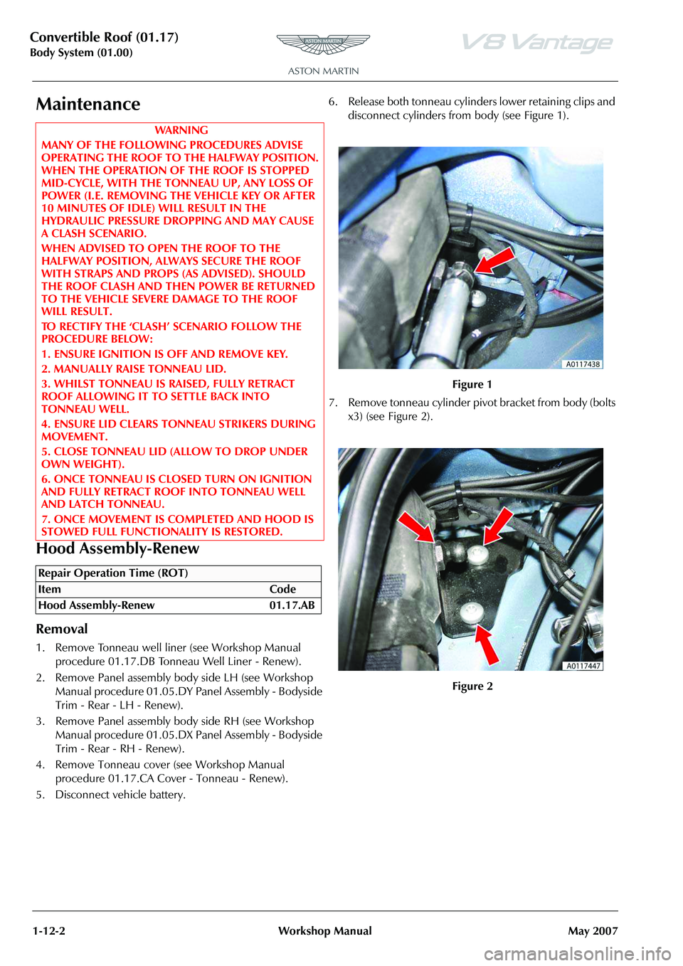
5. Disconnect vehicle battery. 6. Release both tonneau cylinders lower retaining clips and
disconnect cylinders from body (see Figure 1).
7. Remove tonneau cylinder pivot bracket from body (bolts x3) (see Figure 2).
WAR NI NG
MANY OF THE FOLLOWING PROCEDURES ADVISE
OPERATING THE ROOF TO THE HALFWAY POSITION.
WHEN THE OPERATION OF THE ROOF IS STOPPED
MID-CYCLE, WITH THE TO NNEAU UP, ANY LOSS OF
POWER (I.E. REMOVING THE VEHICLE KEY OR AFTER
10 MINUTES OF IDLE) WILL RESULT IN THE
HYDRAULIC PRESSURE DROPPING AND MAY CAUSE
A CLASH SCENARIO.
WHEN ADVISED TO OPEN THE ROOF TO THE
HALFWAY POSITION, ALWA YS SECURE THE ROOF
WITH STRAPS AND PROPS (AS ADVISED). SHOULD
THE ROOF CLASH AND THEN POWER BE RETURNED
TO THE VEHICLE SEVERE DAMAGE TO THE ROOF
WILL RESULT.
TO RECTIFY THE ‘CLASH’ SCENARIO FOLLOW THE
PROCEDURE BELOW:
1. ENSURE IGNITION IS OFF AND REMOVE KEY.
2. MANUALLY RAISE TONNEAU LID.
3. WHILST TONNEAU IS RAISED, FULLY RETRACT
ROOF ALLOWING IT TO SETTLE BACK INTO
TONNEAU WELL.
4. ENSURE LID CLEARS TONNEAU STRIKERS DURING
MOVEMENT.
5. CLOSE TONNEAU LID (ALLOW TO DROP UNDER
OWN WEIGHT).
6. ONCE TONNEAU IS CLOSED TURN ON IGNITION
AND FULLY RETRACT ROOF INTO TONNEAU WELL
AND LATCH TONNEAU.
7. ONCE MOVEMENT IS COMPLETED AND HOOD IS
STOWED FULL FUNCTIONALITY IS RESTORED.
Repair Operation Time (ROT)
Figure 1
Figure 2
Page 143 of 947

Convertible Roof (01.17)
Body System (01.00)
May 2007 Workshop Manual 1-12-5
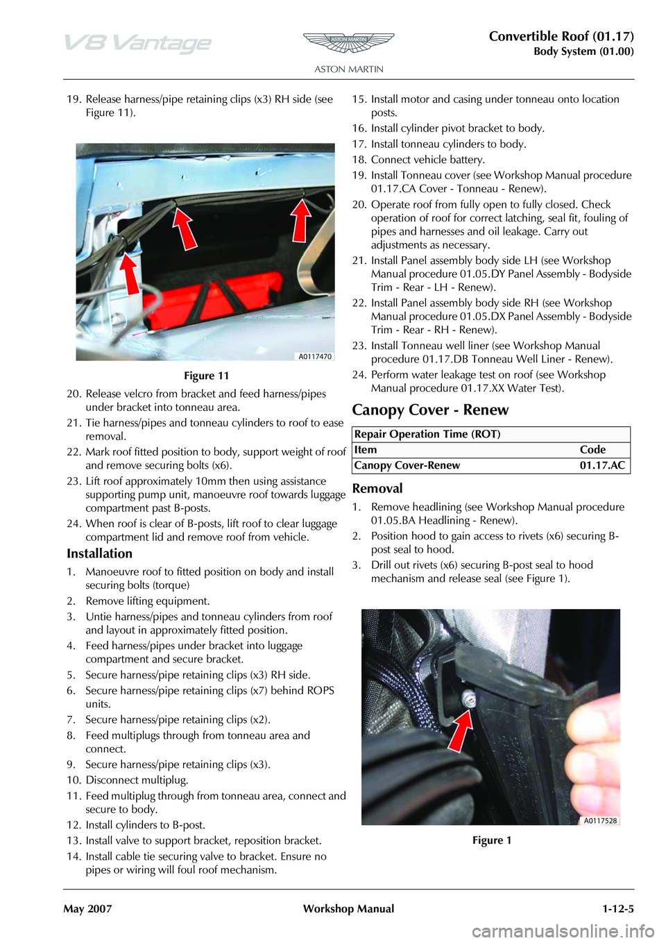
19. Release harness/pipe retaining clips (x3) RH side (see Figure 11).
20. Release velcro from bracket and feed harness/pipes under bracket into tonneau area.
21. Tie harness/pipes and tonneau cylinders to roof to ease removal.
22. Mark roof fitted position to body, support weight of roof and remove securing bolts (x6).
23. Lift roof approximately 10mm then using assistance
supporting pump unit, manoeuvre roof towards luggage
compartment past B-posts.
24. When roof is clear of B-post s, lift roof to clear luggage
compartment lid and remove roof from vehicle.
Installation
1. Manoeuvre roof to fitted position on body and install securing bolts (torque)
2. Remove lifting equipment.
3. Untie harness/pipes and tonneau cylinders from roof and layout in approximately fitted position.
4. Feed harness/pipes under bracket into luggage compartment and secure bracket.
5. Secure harness/pipe retaining clips (x3) RH side.
6. Secure harness/pipe retaining clips (x7) behind ROPS units.
7. Secure harness/pipe retaining clips (x2).
8. Feed multiplugs through from tonneau area and connect.
9. Secure harness/pipe retaining clips (x3).
10. Disconnect multiplug.
11. Feed multiplug through from tonneau area, connect and secure to body.
12. Install cylinders to B-post.
13. Install valve to support bracket, reposition bracket.
14. Install cable tie securing valve to bracket. Ensure no pipes or wiring will foul roof mechanism. 15. Install motor and casing under tonneau onto location
posts.
16. Install cylinder pivot bracket to body.
17. Install tonneau cylinders to body.
18. Connect vehicle battery.
19. Install Tonneau cover (see Workshop Manual procedure 01.17.CA Cover - Tonneau - Renew).
20. Operate roof from fully open to fully closed. Check operation of roof for correct latching, seal fit, fouling of
pipes and harnesses and oil leakage. Carry out
adjustments as necessary.
21. Install Panel assembly bo dy side LH (see Workshop
Manual procedure 01.05.DY Panel Assembly - Bodyside
Trim - Rear - LH - Renew).
22. Install Panel assembly body side RH (see Workshop Manual procedure 01.05.DX Pa nel Assembly - Bodyside
Trim - Rear - RH - Renew).
23. Install Tonneau well line r (see Workshop Manual
procedure 01.17.DB Tonneau Well Liner - Renew).
24. Perform water leakage test on roof (see Workshop Manual procedure 01.17.XX Water Test).
Canopy Cover - Renew
Removal
1. Remove headlining (see Workshop Manual procedure
01.05.BA Headlining - Renew).
2. Position hood to gain access to rivets (x6) securing B- post seal to hood.
3. Drill out rivets (x6) secu ring B-post seal to hood
mechanism and release seal (see Figure 1).
Figure 11
Repair Operation Time (ROT)
Page 144 of 947

Convertible Roof (01.17)
Body System (01.00)1-12-6 Workshop Manual May 2007
4. Release velcro securing canopy to tension belts and remove leaf springs (see Figure 2).
5. Remove screws securing canopy strap to third cross bar (see Figure 3).
6. Mark position of nuts (x4) to aid installation.
7. Remove nuts (x4) securing front seal holders to hood
mechanism and remove holders. 8. Note position of shims and collect (see Figure 4).
9. Remove screws (x11) securing front header canopy
retainer to header rail and remove retainer (see Figure
5).
Figure 2
Figure 3
Figure 4
Figure 5
Page 146 of 947

Convertible Roof (01.17)
Body System (01.00)1-12-8 Workshop Manual May 2007
16. Release double sided tape securing canopy flag to third cross bar (see Figure 10).
17. Release double sided tape securing canopy flag to second cross bar (see Figure 11). 18. Release double sided tape securing canopy flag to first
cross bar (see Figure 12).
19. Using assistance, remove tension cables from canopy
channel and upper B-post slots and remove canopy
cover.
Installation
1. Using assistance, position canopy cover on hood frame and secure to header rail using screws.
2. Feed tension cables through upper B-post slots, through canopy channel and attach to header rail.
3. Secure tension cables to header rail using clips.
4. Install front header canopy retainer and secure with screws excluding outer 2 screws.
5. Secure outer of front hea der retainer with screws.
6. Position hood an midway position and support.
7. Position canopy cover to tension bow and secure to B- post temporarily using self tapping screws.
8. Install leaf springs.
9. Position rear insulation over tension belts.
10. Fully close roof and ensure that rear insulation is in
correct position.
11. Pull leaf spring retaining straps within tension belts through insulation slots and install leaf springs.
12. Attach velcro between canopy cover and tension belt.
13. Pull canopy flag over third cross bar and align holes in flag with those in cross bar.
14. Stick double sided tape to rear edges of canopy flags.
15. Peel back double sided tape of rearmost canopy flag, pull flag over third cross bar, align holes and attach.
16. Repeat for second and first flags and cross bars.
17. Peel back double sided tape on front header flags and cover tension cable clips.
18. Position seal holder to hood mechanism with shims in original positions, fit nuts but do not tighten at this stage.
19. Align to marked position and tighten nuts.
Figure 10
Figure 11
Figure 12
Page 147 of 947

Convertible Roof (01.17)
Body System (01.00)
May 2007 Workshop Manual 1-12-9
20. Secure canopy straps to third cross bar using screws.
21. Position hood to gain access to B-post seal fixings.
22. Remove self tapping screws and secure B-post seal to hood mechanism using rivets starting with the lowest
hole first.
23. Restore roof to original position, raise door glass and
check alignment of front seals.
24. Install headlining (see Workshop Manual procedure
01.05.BA Headlining - Renew).
25. Check operation and fit of hood.
Header Latch Motor - Renew
Removal
1. Remove left-hand header latch flex shaft (see Workshop Manual procedure 01.17.EF Flex Shaft - LH - Renew).
2. Remove right-hand header latch flex shaft (see Workshop Manual procedure 01.17.EG Flex Shaft - RH
- Renew).
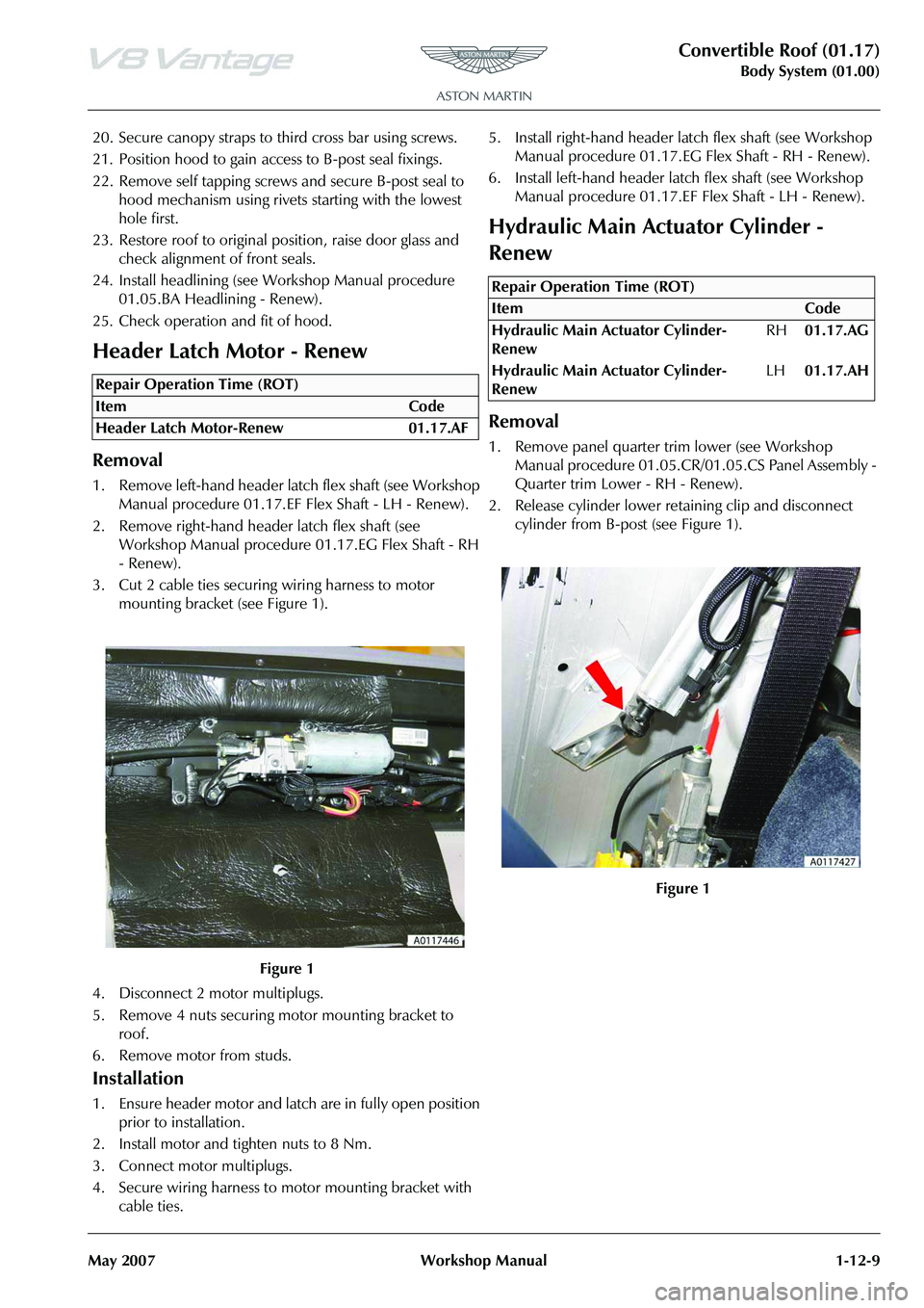
3. Cut 2 cable ties securing wiring harness to motor mounting bracket (see Figure 1).
4. Disconnect 2 motor multiplugs.
5. Remove 4 nuts securing motor mounting bracket to roof.
6. Remove motor from studs.
Installation
1. Ensure header motor and latch are in fully open position prior to installation.
2. Install motor and tighten nuts to 8 Nm.
3. Connect motor multiplugs.
4. Secure wiring harness to motor mounting bracket with cable ties. 5. Install right-hand header la
tch flex shaft (see Workshop
Manual procedure 01.17.EG Flex Shaft - RH - Renew).
6. Install left-hand header latc h flex shaft (see Workshop
Manual procedure 01.17.EF Flex Shaft - LH - Renew).
Hydraulic Main Actuator Cylinder -
Renew
Removal
1. Remove panel quarter trim lower (see Workshop
Manual procedure 01.05.CR/01.05.CS Panel Assembly -
Quarter trim Lower - RH - Renew).
2. Release cylinder lower retaining clip and disconnect cylinder from B-post (see Figure 1).
Repair Operation Time (ROT)
Repair Operation Time (ROT)
Page 163 of 947

Convertible Roof (01.17)
Body System (01.00)
May 2007 Workshop Manual 1-12-25
8. Restore roof and tonneau to original position
Cantrail Cover Trim - Renew
Removal
1. Operate roof to halfway position and support roof when hydraulic pressure drops with suitable straps.
2. Remove Torx screws (x2) securing trim to hood
mechanism and release trim (see Figure 1). 3. Remove bolt securing tensio
n string to trim and remove
trim (see Figure 2).
Installation
1. Position tension string to trim and secure with screw.
2. Install trim to hood and secure with bolts (ensure tension string is positioned either side of rear screw).
3. Restore roof to original position.
B-Post Trim Cover - Renew
Removal
1. Remove cantrail trim (see Workshop Manual procedure 01.17.BT Cover - Trim - Cantrail - Renew).
2. Mark position of screws (x2) to aid installation.
Repair Operation Time (ROT)
Figure 2
Repair Operation Time (ROT)
Page 164 of 947

Convertible Roof (01.17)
Body System (01.00)1-12-26 Workshop Manual May 2007
3. Remove screws (x2) securing trim to hood mechanism and release trim (see Figure 1).
4. Unclip spring securing tension string to hood mechanism (see Figure 2). 5. Remove screw securing tension strap to hood
mechanism and remove trim (see Figure 3).
Installation
1. Pass tension strap through trim and secure to hood mechanism using bolt.
2. Pass tension string through trim and secure tension spring to hood mechanism.
3. Install trim to hood mechanism and secure with screws.
4. Install cantrail trim (see Workshop Manual procedure 01.17.BT Cover - Trim - Cantrail - Renew).
Figure 1
Figure 2
Figure 3
Page 166 of 947

Convertible Roof (01.17)
Body System (01.00)1-12-28 Workshop Manual May 2007
5. Release velcro and clip securing right-hand tonneau well liner edges (see Figure 4).
6. Release velcro and 3 clips securing left-hand tonneau well liner edges (see Figure 5). 7. Release tonneau B-post flap cables from hood linkage
(both sides) (see Figure 6).
8. With assistance, remove tonneau hinge bolts and
remove tonneau cover.
9. Release 2 clips (both sides) securing B-post flap cables to tonneau cover (see Figure 7).
10. Mark mounting position of B-post flaps (both sides).
Figure 4
Figure 5
Figure 6
Figure 7
Page 206 of 947

Convertible Roof (01.17)
Body System (01.00)1-12-68 Workshop Manual May 2007
Removal
1. Access luggage compartment and remove front liner (screws x4, trim clip x1) (see Figure 1)
.
2. Release velcro straps x2 and drain tubes x3.
3. Close luggage compartment.
4. Remove Wind deflector (see Workshop Manual
procedure 01.17.DA Wind Deflector - Renew).
5. Release stiffener, liner trim clip and velcro from around
hood motor (see Figure 2). 6. Release velcro from arou
nd tonneau cylinder and
remove trim clips (x 3) (see Figure 3).
7. Release trim clips (x7) from luggage compartment panel (see Figure 4).
8. Release velcro from behi nd ROPS units and remove
liner.
9. Remove stiffening rod from liner.
Installation
1. Install stiffening rod to liner.
2. Install liner and secure velcro.
3. Install trim clips (x7) to luggage compartment panel.
4. Secure velcro around tonneau cylinder and install trim
clips (x3).
5. Install stiffener, liner trim clip and velcro to around hood motor.
6. Install Wind deflector (see Workshop Manual procedure 01.17.DA Wind Deflector - Renew).
Figure 1
Figure 2
Figure 3
Figure 4
Page 700 of 947

Wiring and Circuit Protection (18.01)
Electric Distribution/Electronic Control (18.00)
May 2007 Workshop Manual 18-1-11
Maintenance
Forward Harness-Renew
Removal
1. Disconnect vehicle battery.
2. Remove LH headlamp (see Workshop Manual procedure 17.01.AB Headlamp Assembly - LH -
Renew).
3. Remove RH headlamp (see Workshop Manual procedure 17.01.BB Headlamp Assembly - RH -
Renew).
4. Release grommet from body, feed harness from inside of vehicle.
5. Disconnect multiplugs (x2) LH and RH side repeaters.
6. Disconnect multiplugs (x2) LH and RH pad wear indicators.
7. Disconnect multiplug (x2) LH and RH wheel speed sensors.
8. Disconnect multiplugs (x2) LH and RH air flow meters.
9. Disconnect multiplugs (x2) LH and RH headlamp bulb
monitoring resistors.
10. Remove nuts (x6) securing LH and RH earth leads to body (x6).
11. Remove screws (x4) LH and RH harness plate to body and release harness from plate.
12. Remove screen washer reservoir (see Workshop Manual procedure 01.16.DA Reserv oir and Motor Assembly -
Windshield Wash - Renew).
13. Remove fusebox (see Workshop Manual procedure 18.01.KD Fuse Box - Engine Bay - Renew).
14. Disconnect multiplug (x1) purge valve.
15. Disconnect multiplug (x1) ABS modulator.
16. Disconnect multiplug (x1) load level sensor.
17. Disconnect multiplugs (x4) forward harness to cabin harness.
18. Remove wiper motor and linkage (see Workshop Manual procedure 01.16.BA Linkage Assembly - Wiper
- Renew).
19. Remove cross member fr ont latch mounting (see
Workshop Manual procedure 01.14.BD Latch Assembly
- Hood - Renew).
20. Remove nuts (x2) securing earth leads to body (x2).
21. Disconnect multiplug (x1) heated front windshield.
22. Disconnect multiplug PAS sensor.
23. Disconnect multiplugs (x2) A/C compressor. 24. Disconnect multiplug (x1) horn.
25. Release forward harness to engine harness multiplug
(x1) from inner wing and di sconnect multiplugs (x2).
26. Disconnect multiplug (x2) cooling fans.
27. Disconnect multiplug (x1) ambient air temperature sensor.
28. Disconnect multiplugs (X2) crash sensors.
29. Release harness clips (70) and remove harness.
Installation
1. Layout harness around engine bay, feed harness into cabin area and secure grommet.
2. Secure forward harness clips (x70) to body.
3. Connect multiplug (x2) LH and RH side repeaters.
4. Connect multiplug (x2) LH and RH pad wear indicators.
5. Connect multiplugs (X2) LH and RH wheel speed sensors.
6. Connect multiplugs (x2) LH and RH air flow meters.
7. Connect multiplugs (x2) LH and RH headlamp bulb
monitoring resistors.
8. Position earth leads (x6), install and torque tighten nuts (x6).
9. Secure harness to plates (x2) and install plates to body.
10. Connect multiplug (x1) purge valve.
11. Install washer reservoi r (see Workshop Manual
procedure 01.16.DA Reservoir and Motor Assembly -
Windshield Wash - Renew).
12. Install fuse box (see Workshop Manual procedure 18.01.KD Fuse Box - Engine Bay - Renew).
13. Connect multiplug (x1) ABS connector.
14. Connect multiplug (x1) load level sensor.
15. Disconnect multiplug (x4) forward harness to cabin harness.
16. Connect multiplug (x1) heated front screen.
17. Connect multiplug (x1) PAS sensor.
18. Connect multiplugs (x2) A/C.
19. Connect multiplug (x1) horn
20. Position earth leads (x2), install and torque tighten nuts (x2).
21. Secure forward harness multiplug (x1) to inner wing and connect multiplugs (x2).
22. Connect multiplug (x2) cooling fans.
23. Connect multiplug (x1) am bient air temperature sensor.
24. Connect multiplugs (X2) crash sensors.
25. Install cross member front latch mounting 01.14.BD Latch Assembly - Hood - Renew).
26. Install wiper motor and linkage (see Workshop Manual procedure 01.16.BA Linkage Assembly - Wiper -
Renew).
27. Install LH headlamp (see Workshop Manual procedure
17.01.AB Headlamp Assembly - LH - Renew).
28. Install RH headlamp (see Workshop Manual procedure 17.01.BB Headlamp Assembly - RH - Renew).
29. Connect vehicle battery.
Repair Operation Time (ROT)
Warning
To prevent damage to elec trical components, always
disconnect the vehicle battery when working on the
vehicle's electrical system. The earth lead (- ve) must be disconnected first and reconnected last.