hood release ASTON MARTIN V8 VANTAGE 2010 Workshop Manual
[x] Cancel search | Manufacturer: ASTON MARTIN, Model Year: 2010, Model line: V8 VANTAGE, Model: ASTON MARTIN V8 VANTAGE 2010Pages: 947, PDF Size: 43.21 MB
Page 13 of 947
Issue 5, January 2010 Workshop Manual 1-1-1
Body System (01.00)
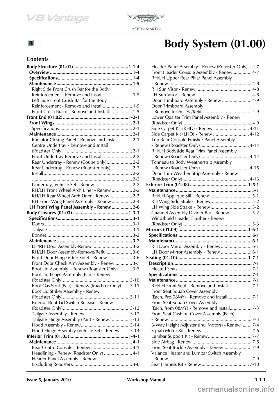
Contents
Body Structure (01.01)........................................... 1-1-4Overview ................................................................ 1-4
Specifications.......................................................... 1-4
Maintenance ........................................................... 1-5Right Side Front Crush Bar for the Body
Reinforcement - Remove and Install ....................... 1-5
Left Side Front Crush Bar for the Body
Reinforcement - Remove and Install ....................... 1-5
Front Crush Brace - Remove and Install .................. 1-5
Front End (01.02) ................................................... 1-2-1 Front Wings ............................................................ 2-1Specifications ......................................................... 2-1
Maintenance ........................................................... 2-1 Radiator Closing Panel - Remove and Install ........... 2-1
Centre Undertray - Remove and Install
(Roadster Only) ..................................................... 2-1
Front Undertray-Remove and Install ....................... 2-2
Rear Undertray - Renew (Coupe only).................... 2-2
Rear Undertray - Renew (Roadster only) ................ 2-2
Install ..................................................................... 2-2.............................................................................. 2-2
Undertray, Vehicle Set - Renew ............................. 2-2
RH/LH Front Wheel Arch Liner - Renew ................ 2-2
RH/LH Rear Wheel Arch Liner - Renew ................. 2-3
RH Front Wing Panel Assembly - Renew ................ 2-4
LH Front Wing Panel Assembly - Renew ................ 2-6
Body Closures (01.03) ........................................... 1-3-1 Specifications.......................................................... 3-1Doors .................................................................... 3-1
Tailgate .................................................................. 3-1
Bonnet................................................................... 3-2
Maintenance ........................................................... 3-2 LH/RH Door Assembly-Renew ............................... 3-2
RH/LH Door Assembly-Remove/Refit ..................... 3-6
Front Door Hinge (One Side) - Renew ................... 3-6
Front Door Check Arm Assembly - Renew ............. 3-7
Boot Lid Assembly - Renew (Roadster Only) ........... 3-7
Boot Lid Hinge Assembly (Pair) - Renew
(Roadster Only) .................................................... 3-10
Boot Gas Strut (Pair) - Renew (Roadster Only) ...... 3-11
Boot Lid Striker Assembly - Renew
(Roadster Only) .................................................... 3-11
Exterior Boot Lid Switch Release - Renew
(Roadster Only) .................................................... 3-12
Tailgate Assembly - Renew ................................... 3-12
Tailgate Hinge Assembly (Pair) - Renew ................ 3-13
Hood Assembly - Renew ...................................... 3-14
Hood Hinge Assembly (Vehicle Set) - Renew ....... 3-14
Interior Trim (01.05).............................................. 1-4-1 Maintenance ........................................................... 4-1Rear Centre Console - Renew ................................ 4-1
Headlining - Renew (Roadster Only) ...................... 4-1
Header Panel As sembly - Renew
(Excluding Roadster)............................................... 4-6 Header Panel Assembly - Renew (Roadster Only)... 4-7
Front Header Console Assembly - Renew............... 4-7
RH/LH Upper Rear Pillar Panel Assembly
- Renew ................................................................. 4-8
RH Sun Visor - Renew ........................................... 4-8
LH Sun Visor - Renew ............................................ 4-8
Door Trimboard Assembly - Renew ....................... 4-9
Door Trimboard Assembly
- Remove for Access/Refit ...................................... 4-9
Lower Quarter Trim Panel Assembly - Renew
(Roadster Only)...................................................... 4-9
Side Carpet Kit (RHD) - Renew ............................ 4-11
Side Carpet Kit (LHD) - Renew ............................ 4-12
Top Rear Console Fini
sher Panel Assembly
- Renew (Roadster Only) ...................................... 4-14
RH/LH Bodyside Rear Trim Panel Assembly
- Renew (Roadster Only) ...................................... 4-14
Tonneau to Body Weatherstrip Assembly
- Renew (Roadster Only) ...................................... 4-15
Door Trim Weather Strip Assembly - Renew
(Roadster Only).................................................... 4-16
Exterior Trim (01.08) ............................................. 1-5-1 Maintenance ........................................................... 5-1RH/LH Applique Sill - Renew ................................. 5-1
RH Wing Side Strake - Renew................................ 5-2
LH Wing Side Strake - Renew ................................ 5-2
Channel Assembly Divider Bar - Renew ................. 5-2
Windshield Header Finisher - Renew
(Roadster Only)...................................................... 5-3
Mirrors (01.09) ...................................................... 1-6-1 Specifications ......................................................... 6-1
Maintenance ........................................................... 6-1RH Door Mirror Assembly - Renew ........................ 6-1
LH Door Mirror Assembly - Renew ........................ 6-1
Seating (01.10)....................................................... 1-7-1 Description ............................................................. 7-1Heated Seats ......................................................... 7-1
Specifications ........................................................ 7-1
Maintenance ........................................................... 7-1 RH/LH Front Seat - Remove and Install .................. 7-1
Front Seat Squab Cover Assembly
(Each, Pre-08MY) - Remove and Install .................. 7-1
Front Seat Squab Cover Assembly
(Each, from 08MY) - Remove and Install................. 7-3
Front Seat Cushion Cover Assembly (Each)
- Renew ................................................................. 7-3
6-Way Height Adjuster (Inc. Motors) - Renew ........ 7-4
Squab Motor Kit - Renew....................................... 7-6
Lumbar Support Kit - Renew .................................. 7-7
Side Airbag - Renew .............................................. 7-8
Front Seat Buckle Assembly - Renew...................... 7-9
Valance Heater and Lumbar Switch Assembly
- Renew ................................................................. 7-9
Seat Harness Kit - Renew ..................................... 7-10
Page 14 of 947
1-1-2 Workshop Manual Issue 5, January 2010
RH/LH Seat Switchpack Assembly - Renew...........7-13
Lumbar Pump for the Front Seat (From 08MY)
- Remove and Install.............................................7-13
Lumbar Valve for the Front Seat (From 08MY)
- Remove and Install.............................................7-14
Lumbar Bladder for the Front Seat (From 08MY)
- Remove and Install.............................................7-14
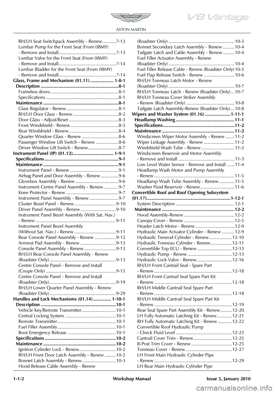
Glass, Frame and Mechanism (01.11) .................. 1-8-1 Description .............................................................8-1 Frameless doors......................................................8-1
Specifications .........................................................8-1
Maintenance ...........................................................8-1 Glass Regulator - Renew .........................................8-1
RH/LH Door Glass - Renew ....................................8-2
Door Glass - Adjust/Reset .......................................8-3
Front Windshield - Renew ......................................8-3
Rear Windshield - Renew .......................................8-4
Quarter Window Glass - Renew .............................8-6
Passenger Window Lift Switch - Renew ..................8-6
Driver Window Lift Switch - Renew........................8-7
Instrument Panel (IP) (01.12)................................ 1-9-1 Specifications ..........................................................9-1
Maintenance ...........................................................9-1 Instrument Panel - Renew ......................................9-1
Airbag Panel and Door Assembly - Renew ..............9-6
Glovebox Assembly - Renew ..................................9-6
Instrument Centre Panel Asse mbly - Renew............9-7
Knee Protector - Renew .........................................9-7
Instrument Panel As sembly - Renew .......................9-7
Cluster Bezel Panel - Renew .................................9-10
Driver Panel Assembly - Renew ............................9-10
Instrument Panel Bezel A ssembly (With Sat. Nav.)
- Renew ...............................................................9-11
Instrument Panel Bezel Assembly
(Without Sat. Nav.) - Renew .................................9-11
Rear Console Panel Assembly - Renew .................9-12
Armrest Pad Assembly - Renew ............................9-13
Console Panel Assembly - Renew .........................9-13
RH/LH Rear Console Pa nel Assembly - Renew
(Roadster Only) ....................................................9-13
Centre Console Panel - Remove and Install
(Coupe Only) .......................................................9-15
Centre Console Panel - Remove and Install
(Roadster Only) ....................................................9-19
RH/LH Lower Quarter Panel Assembly - Renew
(Roadster Only) ....................................................9-29
Handles and Lock Mechanisms (01.14) .............. 1-10-1 Description ...........................................................10-1 Vehicle Key/Remote Transmitter...........................10-1
Central Locking System ........................................10-1
Remote Transmitter ..............................................10-1
Fuel Filler Assembly ..............................................10-1
Boot Emergency Release ....... ...............................10-1
Specifications ........................................................10-2
Maintenance .........................................................10-2 Ignition Cylinder Lock - Re new.............................10-2
RH/LH Front Door Latch As sembly - Renew .........10-2
Bonnet Latch Assembly - Renew...........................10-3
Hood Release Cable Assembly - Renew (Roadster Only) .................................................... 10-3
Bonnet Secondary Latch Asse
mbly - Renew ......... 10-4
Tailgate Latch and Cable Assembly - Renew ......... 10-4
Fuel Filler Actuator Assembly - Renew
(Roadster Only) .................................................... 10-4
Fuel Filler Release Cable - Renew (Roadster Only) 10-5
Fuel Flap Release Switch - Renew ........................ 10-6
RH/LH Tonneau Latch Motor - Renew
(Roadster Only) .................................................... 10-7
RH/LH Tonneau Latch - Renew (Roadster Only) ... 10-7
RH/LH Tonneau Cover Striker Assembly
- Renew (Roadster Only) ...................................... 10-8
Tailgate Latch Assembly-Renew (Roadster Only) ... 10-8
Wipers and Washer System (01.16) ....................1-11-1 Headlamp Washing .............................................. 11-1
Specifications ........................................................ 11-2
Maintenance ......................................................... 11-2 Windscreen Wiper Motor As sembly - Renew ....... 11-2
Wiper Linkage Assembly - Renew ........................ 11-2
Windshield Wash Tube - Renew .......................... 11-2
Windscreen Reservoir and Motor Assembly
- Remove and Install ............................................ 11-3
Low Level Water Sensor - Remove and Install ...... 11-4
Headlamp Wash Motor and Pump Assembly
- Renew ............................................................... 11-5
Headlamp Wash Tube Assembly - Renew ............ 11-5
Washer Fluid Reservoir - Renew........................... 11-6
Convertible Roof and Roof Opening Subsystem
(01.17)..................................................................1-12-1 System Description .............................................. 12-1
Maintenance ......................................................... 12-2 Hood Assembly-Renew ........................................ 12-2
Canopy Cover - Renew ........................................ 12-5
Header Latch Motor - Renew ............................... 12-9
Hydraulic Main Actuator Cy linder - Renew .......... 12-9
Hydraulic Tensrod Cylinder - Renew .................. 12-10
Hydraulic Tonneau Cylinder - Renew................. 12-11
Convertible Top ECU - Renew ........................... 12-13
Hydraulic Pump - Renew ................................... 12-13
Hydraulic Lock Valve - Renew............................ 12-16
RH/LH Front Cantrail Seal - Spare Part
- Renew ............................................................. 12-18
RH/LH Front Cantrail Seal Spare Part Kit
- Renew ............................................................. 12-18
RH/LH Middle Cantrail Seal Spare Part
- Renew ............................................................. 12-18
RH/LH Middle Cantrail Seal Spare Part Kit
- Renew ............................................................. 12-19
Rear Seal Spare Part Assembly Kit - Renew ......... 12-20
LH Fully Automatic Latching Kit - Renew............ 12-21
RH Fully Automatic Latching Kit - Renew ........... 12-22
Convertible Roof Hydraulic Pump
- Check Fluid Level ............................................ 12-23
Cantrail Cover Trim - Renew .............................. 12-25
B-Post Trim Cover - Renew ................................ 12-25
Tonneau Cover - Renew .................................... 12-27
LH Front Main Hydraulic Cylinder Pipe
- Renew ............................................................. 12-29
LH Rear Main Hydraulic Cylinder Pipe
Page 40 of 947
Body Closures (01.03)
Body System (01.00)1-3-14 Workshop Manual May 2007
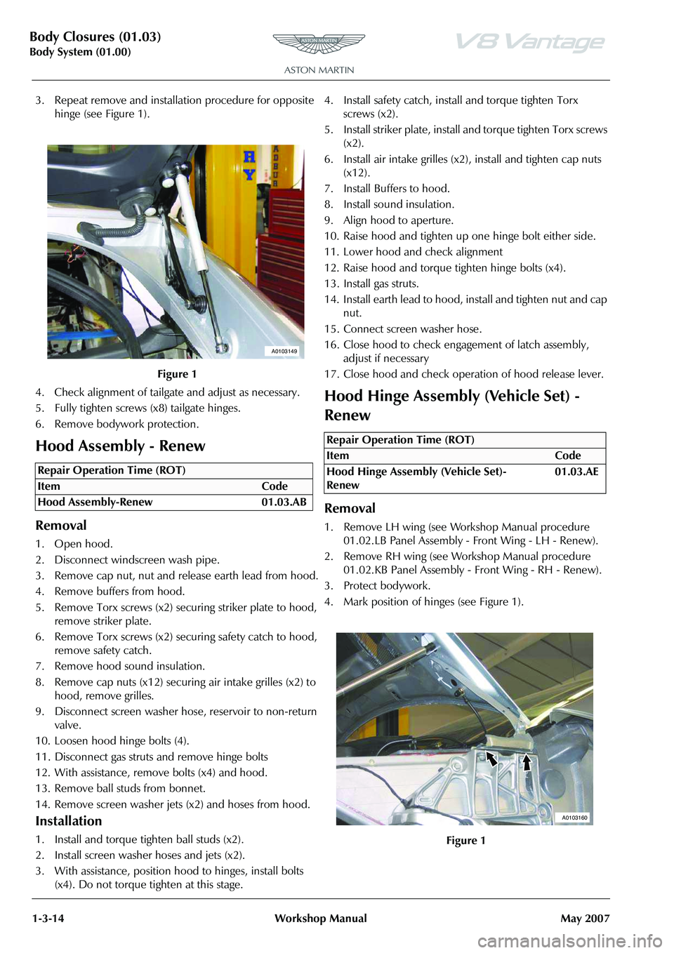
3. Repeat remove and installa tion procedure for opposite
hinge (see Figure 1).
4. Check alignment of tailgate and adjust as necessary.
5. Fully tighten screws (x8) tailgate hinges.
6. Remove bodywork protection.
Hood Assembly - Renew
Removal
1. Open hood.
2. Disconnect windscreen wash pipe.
3. Remove cap nut, nut and release earth lead from hood.
4. Remove buffers from hood.
5. Remove Torx screws (x2) se curing striker plate to hood,
remove striker plate.
6. Remove Torx screws (x2) se curing safety catch to hood,
remove safety catch.
7. Remove hood sound insulation.
8. Remove cap nuts (x12) securing air intake grilles (x2) to
hood, remove grilles.
9. Disconnect screen washer hos e, reservoir to non-return
valve.
10. Loosen hood hinge bolts (4).
11. Disconnect gas struts and remove hinge bolts
12. With assistance, remove bolts (x4) and hood.
13. Remove ball studs from bonnet.
14. Remove screen washer jets (x2) and hoses from hood.
Installation
1. Install and torque tighten ball studs (x2).
2. Install screen washer hoses and jets (x2).
3. With assistance, position hood to hinges, install bolts
(x4). Do not torque tighten at this stage. 4. Install safety catch, install and torque tighten Torx
screws (x2).
5. Install striker plate, install and torque tighten Torx screws (x2).
6. Install air intake grilles (x2), install and tighten cap nuts (x12).
7. Install Buffers to hood.
8. Install sound insulation.
9. Align hood to aperture.
10. Raise hood and tighten up one hinge bolt either side.
11. Lower hood and check alignment
12. Raise hood and torque tighten hinge bolts (x4).
13. Install gas struts.
14. Install earth lead to hood, install and tighten nut and cap nut.
15. Connect screen washer hose.
16. Close hood to check enga gement of latch assembly,
adjust if necessary
17. Close hood and check operation of hood release lever.
Hood Hinge Assembly (Vehicle Set) -
Renew
Removal
1. Remove LH wing (see Workshop Manual procedure 01.02.LB Panel Assembly - Front Wing - LH - Renew).
2. Remove RH wing (see Workshop Manual procedure 01.02.KB Panel Assembly - Front Wing - RH - Renew).
3. Protect bodywork.
4. Mark position of hinges (see Figure 1).
Figure 1
Repair Operation Time (ROT)
A0103149
Repair Operation Time (ROT)
ItemCode
Hood Hinge Assembly (Vehicle Set)-
Renew 01.03.AE
Figure 1
A0103160
Page 46 of 947
Interior Trim (01.05)
Body System (01.00)1-4-4 Workshop Manual Issue 5, January 2010
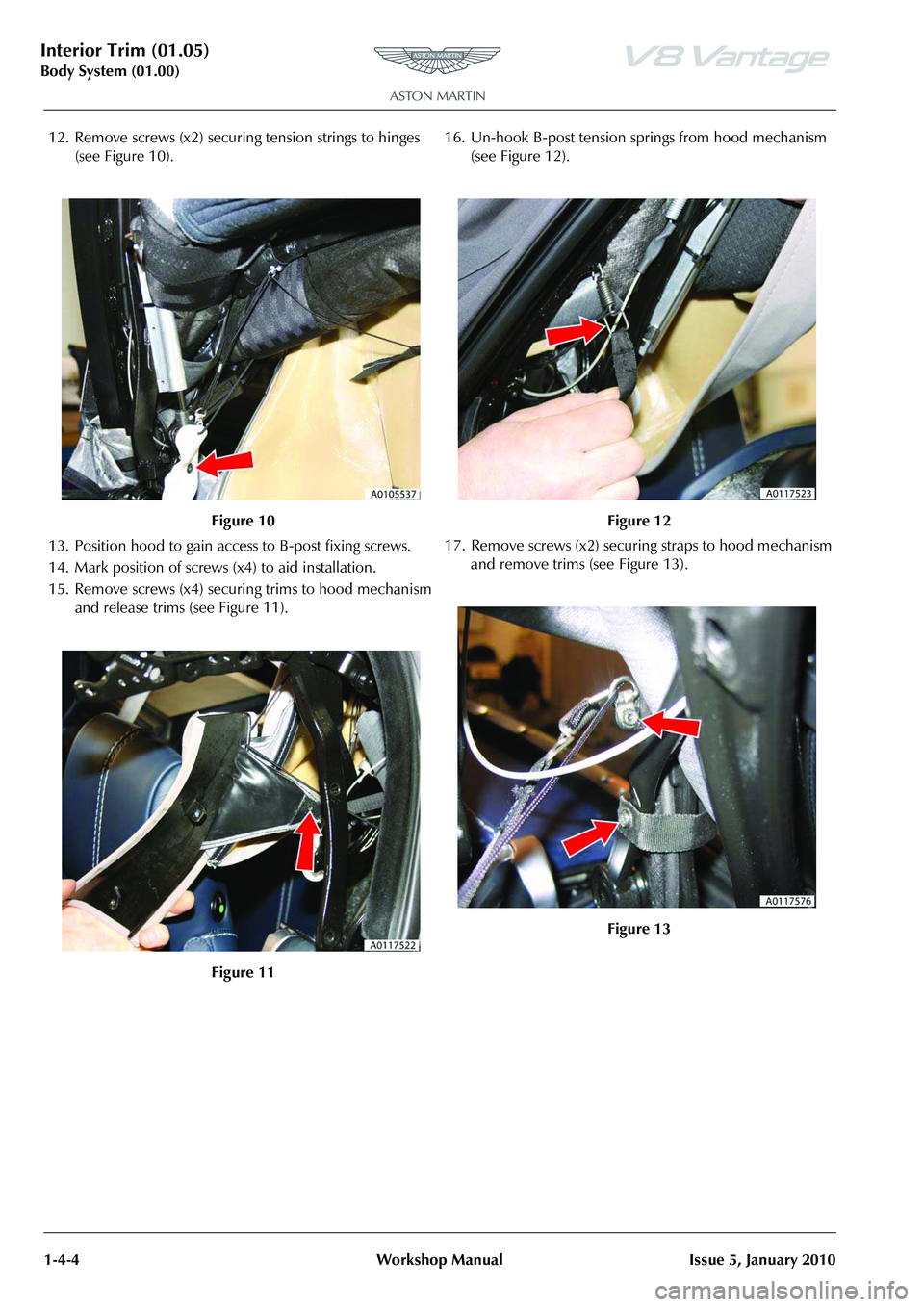
12. Remove screws (x2) securing tension strings to hinges (see Figure 10).
13. Position hood to gain acce ss to B-post fixing screws.
14. Mark position of screws (x4) to aid installation.
15. Remove screws (x4) securi ng trims to hood mechanism
and release trims (see Figure 11). 16. Un-hook B-post tension springs from hood mechanism
(see Figure 12).
17. Remove screws (x2) securi ng straps to hood mechanism
and remove trims (see Figure 13).
Figure 10
Figure 11
Figure 12
Figure 13
Page 47 of 947

Interior Trim (01.05)
Body System (01.00)
Issue 5, January 2010 Workshop Manual 1-4-5
18. Remove screws (x5) securing headlining to second cross bar (see Figure 14).
19. Remove screws (x2) securi ng headlining straps and
tension strings to hood me chanism (see Figure 15).
20. Remove screws (x5) securing headlining to first cross
bar. 21. Remove screws (x2) secu
ring tension strings to
underside of header rail (see Figure 16).
22. Release front of headlini ng from mounting rail and
remove headlining (see Figure 17).
23. Remove headlining bows from pockets.
Installation
1. Install headlining bows to pockets.
2. Install headlining and mount to front rail. Ensure an equal amount of overhang on each side.
3. Secure tension strings to un derside of header rail using
screws.
4. Secure headlining to first cross bar using screws (start
with the middle screw and work outboard).
5. Secure headlining straps and tension strings to hood
mechanism with screws.
6. Secure headlining to second cross bar using screws (start
with the middle screw and work outboard).
Figure 14
Figure 15
Figure 16
Figure 17
Page 79 of 947
Seating (01.10)
Body System (01.00)
Issue 4, November 2008 Workshop Manual 1-7-13
11. Secure cover to bottom of seat back shell.
12. Secure cover to seat back shell (studs and velcro).
13. Install airbag module (bolt x1) (torque).
14. Install multiplug bracket fixing.
15. Connect airbag multiplu g and secure to bracket.
16. Install lever cover.
17. Install release lever.
18. Install seat 6 way height adjuster (see Workshop Manual procedure 01.10.AE 6 Way Height Adjuster - Inc.
Motors - Renew).
RH/LH Seat Switchpack Assembly -
Renew
Removal
1. Remove instrument panel bezel assembly (see Workshop Manual procedure 01.12.AV Bezel Assembly
- Instrument Panel - Remove for Access and Refit).
2. Remove console panel assembly (see Workshop Manual procedure 01.12.DB Panel Assembly Console - Renew).
3. Remove instrument cluster hood (6 clips)
4. Remove passenger upper ou ter panel assembly (see
Workshop Manual procedure 01.12.AE Panel Assembly
- IP - Upper - Passenger - Renew).
5. Remove passenger panel assembly (4 clips and 4 screws)
6. Remove driver's upper inner panel assembly (5 clips)
7. Remove driver's upper outer panel assembly (4 clips)
8. Remove driver's panel assembly (4 clips and 3 screws)
9. Remove receiver and audio media system panel screws (x4), disconnect multiplugs (x12).
10. Pull back carpet and disconnect seat adjust switch multiplugs (x6), release harness clip (x2)
11. Remove instrument centre panel assembly
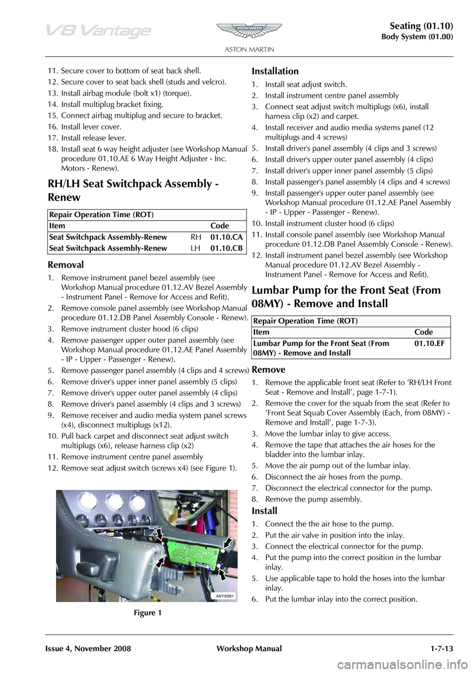
12. Remove seat adjust switch (screws x4) (see Figure 1).
Installation
1. Install seat adjust switch.
2. Install instrument centre panel assembly
3. Connect seat adjust switch multiplugs (x6), install
harness clip (x2) and carpet.
4. Install receiver and audio media systems panel (12 multiplugs and 4 screws)
5. Install driver's panel asse mbly (4 clips and 3 screws)
6. Install driver's upper oute r panel assembly (4 clips)
7. Install driver's upper inne r panel assembly (5 clips)
8. Install passenger's panel assembly (4 clips and 4 screws)
9. Install passenger's upper outer panel assembly (see
Workshop Manual procedure 01.12.AE Panel Assembly
- IP - Upper - Passenger - Renew).
10. Install instrument cluster hood (6 clips)
11. Install console panel assemb ly (see Workshop Manual
procedure 01.12.DB Panel Assembly Console - Renew).
12. Install instrument panel be zel assembly (see Workshop
Manual procedure 01.12.AV Bezel Assembly -
Instrument Panel - Remove for Access and Refit).
Lumbar Pump for the Front Seat (From
08MY) - Remove and Install
Remove
1. Remove the applicable front seat (Refer to ’RH/LH Front Seat - Remove and Install’, page 1-7-1).
2. Remove the cover for the squab from the seat (Refer to ’Front Seat Squab Cover Assembly (Each, from 08MY) -
Remove and Install’, page 1-7-3).
3. Move the lumbar inlay to give access.
4. Remove the tape that attaches the air hoses for the bladder into the lumbar inlay.
5. Move the air pump out of the lumbar inlay.
6. Disconnect the air hoses from the pump.
7. Disconnect the electrical connector for the pump.
8. Remove the pump assembly.
Install
1. Connect the the air hose to the pump.
2. Put the air valve in position into the inlay.
3. Connect the electrical connector for the pump.
4. Put the pump into the correct position in the lumbar inlay.
5. Use applicable tape to hold the hoses into the lumbar inlay.
6. Put the lumbar inlay into the correct position.
Repair Operation Time (ROT)
A0110231
Repair Operation Time (ROT)
Page 95 of 947
Instrument Panel (IP) (01.12)
Body System (01.00)
Issue 5, January 2010 Workshop Manual 1-9-7
Instrument Centre Panel Assembly -
Renew
1. Remove instrument panel bezel assembly (see Workshop Manual procedure 01.12.AV Bezel Assembly
- Instrument Panel - Remove for Access and Refit).
2. Remove console panel assembly (see Workshop Manual procedure 01.12.DB Panel Assembly Console - Renew).
3. Remove instrument cluster hood (6 clips)
4. Remove passenger upper ou ter panel assembly (see
Workshop Manual procedure 01.12.AE Panel Assembly
- IP - Upper - Passenger - Renew).
5. Remove passenger panel assembly (4 clips and 4 screws)
6. Remove driver's upper inner panel assembly (5 clips)
7. Remove driver's upper outer panel assembly (4 clips)
8. Remove driver's panel assembly (4 clips and 3 screws)
9. Remove receiver and audio media system panel screws (x4), disconnect multiplugs (x12).
10. Pull back carpet and disconnect seat adjust switch multiplugs (x6), release harness clip (x2)
11. Remove instrument centre panel assembly
12. Remove seat adjust switches (screws x8).
Installation
1. Install seat adjust switches (screws x8).
2. Install instrument centre panel assembly
3. Connect seat adjust switch multiplugs (x6), install harness clip (x2) and carpet.
4. Install receiver and audio media systems panel (12 multiplugs and 4 screws)
5. Install driver's panel assembly (4 clips and 3 screws)
6. Install driver's upper oute r panel assembly (4 clips)
7. Install driver's upper inne r panel assembly (5 clips)
8. Install passenger's panel assembly (4 clips and 4 screws)
9. Install passenger's upper outer panel assembly (see Workshop Manual procedure 01.12.AE Panel Assembly
- IP - Upper - Passenger - Renew).
10. Install instrument cl uster hood (6 clips)
11. Install console panel asse mbly (see Workshop Manual
procedure 01.12.DB Panel Assembly Console - Renew).
12. Install instrument panel be zel assembly (see Workshop
Manual procedure 01.12.AV Bezel Assembly -
Instrument Panel - Remove for Access and Refit).
Knee Protector - Renew
Removal
1. Remove driver's lower panel assembly (7 clips) and disconnect air temperature pipe.
2. Disconnect footwell light and remove unit from panel.
3. Mark one socket for relocation and remove diagnostic sockets (x2) from panel.
4. Remove pop-rivets (x5), sc rews (x4) and remove panel.
Installation
1. Align knee protector panel in position and secure with
screws (x4).
2. Install pop-rivets (x5).
3. Install diagnostic sockets (x2) (ensure marked socket is in correct location).
4. Install footwell light and reconnect multiplug.
5. Install driver's lower panel assembly (7 clips) and connect air temperature pipe.
Instrument Panel Assembly - Renew
Removal
1. Remove Instrument pane l assembly (see Workshop
Manual procedure 01.12.AB Instrument Panel - Facia
Assembly - Remo ve for Access and Refit).
2. Remove steering column (bolts x4, multiplugs x5).
3. Remove passenger air bag module (screws x4).
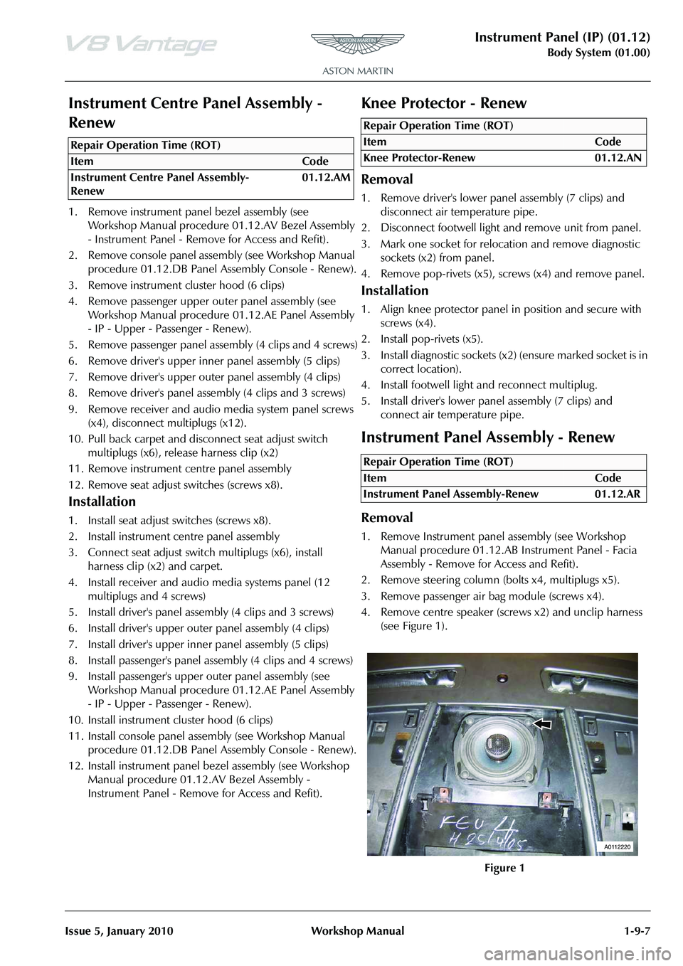
4. Remove centre speaker (screws x2) and unclip harness (see Figure 1).
Repair Operation Time (ROT)
Repair Operation Time (ROT)
Repair Operation Time (ROT)
A0112220
Page 99 of 947

Instrument Panel (IP) (01.12)
Body System (01.00)
Issue 5, January 2010 Workshop Manual 1-9-11
2. Remove driver's upper outer panel assembly (4 clips) (see Figure 2).
3. Remove driver's upper inner panel assembly (5 clips) (see Figure 3).
4. Remove driver's panel assembly (3 screws and 4 clips).
Installation
1. Install driver's panel assembly (3 screws and 4 clips).
2. Install driver's upper inne r panel assembly (5 clips).
3. Install driver's upper oute r panel assembly (4 clips).
4. Install instrument cluster hood assembly (6 clips).
Instrument Panel Bezel Assembly (With
Sat. Nav.) - Renew
Removal
1. Using tool (501 - 108), release instrument panel bezel
assembly clips (x4) from IP (restrain panel movement). 2. Disconnect multiplug (x1)
starter button and remove
panel assembly (s ee Figure 1).
3. Remove starter button from instrument panel bezel assembly.
4. Remove screws (x6) air vent s (x2) to bezel assembly and
remove air vents.
5. Remove screws (x11) satelli te navigation screen panel
from instrument pa nel bezel assembly.
6. Remove Satellite screen panel.
Installation
1. install satellite screen panel (screws x 11) to bezel assembly.
2. Install air vents (x2).
3. Install starter button.
4. Position panel assembly, co nnect multiplug (x1) starter
button.
5. Install panel and secure in clips (x4).
Instrument Panel Bezel Assembly
(Without Sat. Nav.) - Renew
Removal
1. Using tool (501 - 108), release instrument panel bezel assembly clips (x4) from IP (restrain panel movement).
Figure 2
Figure 3
Repair Operation Time (ROT)
Figure 1
Repair Operation Time (ROT)
A0112218
Page 123 of 947
Handles and Lock Mechanisms (01.14)
Body System (01.00)
May 2007 Workshop Manual 1-10-3
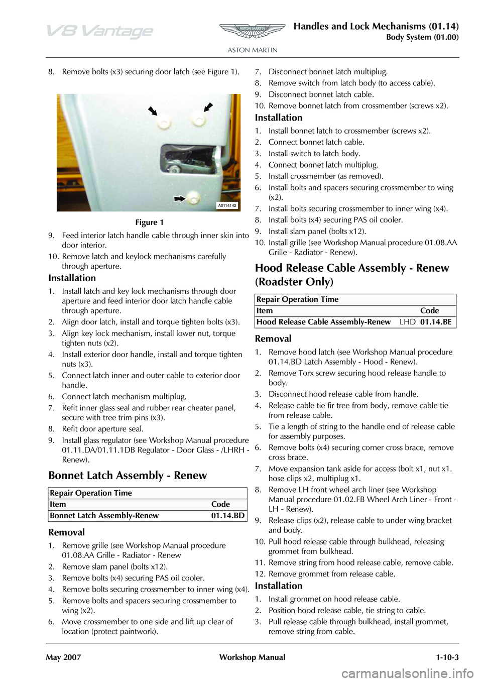
8. Remove bolts (x3) securing door latch (see Figure 1).
9. Feed interior latch handle cable through inner skin into door interior.
10. Remove latch and keylock mechanisms carefully through aperture.
Installation
1. Install latch and key lock mechanisms through door aperture and feed interior door latch handle cable
through aperture.
2. Align door latch, install and torque tighten bolts (x3).
3. Align key lock mechanism, install lower nut, torque tighten nuts (x2).
4. Install exterior door handle, install and torque tighten nuts (x3).
5. Connect latch inner and outer cable to exterior door handle.
6. Connect latch mechanism multiplug.
7. Refit inner glass seal and rubber rear cheater panel, secure with tree trim pins (x3).
8. Refit door aperture seal.
9. Install glass regulator (see Workshop Manual procedure 01.11.DA/01.11.1DB Regulato r - Door Glass - /LHRH -
Renew).
Bonnet Latch Assembly - Renew
Removal
1. Remove grille (see Workshop Manual procedure 01.08.AA Grille - Radiator - Renew
2. Remove slam panel (bolts x12).
3. Remove bolts (x4) securing PAS oil cooler.
4. Remove bolts securing crossmember to inner wing (x4).
5. Remove bolts and spacers securing crossmember to wing (x2).
6. Move crossmember to one side and lift up clear of location (protect paintwork). 7. Disconnect bonnet latch multiplug.
8. Remove switch from latch body (to access cable).
9. Disconnect bonnet latch cable.
10. Remove bonnet latch from
crossmember (screws x2).
Installation
1. Install bonnet latch to crossmember (screws x2).
2. Connect bonnet latch cable.
3. Install switch to latch body.
4. Connect bonnet latch multiplug.
5. Install crossmember (as removed).
6. Install bolts and spacers securing crossmember to wing
(x2).
7. Install bolts securing cros smember to inner wing (x4).
8. Install bolts (x4) securing PAS oil cooler.
9. Install slam panel (bolts x12).
10. Install grille (see Workshop Manual procedure 01.08.AA
Grille - Radiator - Renew).
Hood Release Cable Assembly - Renew
(Roadster Only)
Removal
1. Remove hood latch (see Wo rkshop Manual procedure
01.14.BD Latch Assembly - Hood - Renew).
2. Remove Torx screw securi ng hood release handle to
body.
3. Disconnect hood releas e cable from handle.
4. Release cable tie fir tree fr om body, remove cable tie
from release cable.
5. Tie a length of string to the handle end of release cable for assembly purposes.
6. Remove bolts (x4) securing corner cross brace, remove
cross brace.
7. Move expansion tank aside for access (bolt x1, nut x1. hose clips x2, multiplug x1.
8. Remove LH front wheel arch liner (see Workshop Manual procedure 01.02.FB Wheel Arch Liner - Front -
LH - Renew).
9. Release clips (x2), release cable to under wing bracket and body.
10. Pull hood release cable th rough bulkhead, releasing
grommet from bulkhead.
11. Remove string from hood release cable, remove cable.
12. Remove grommet from release cable.
Installation
1. Install grommet on hood release cable.
2. Position hood release cable, tie string to cable.
3. Pull release cable through bulkhead, install grommet, remove string from cable.
Figure 1
Repair Operation Time
ItemCode
Bonnet Latch Assembly-Renew 01.14.BD
A0114142
Repair Operation Time
ItemCode
Hood Release Cable Assembly-Renew LHD01.14.BE
Page 124 of 947
Handles and Lock Mechanisms (01.14)
Body System (01.00)1-10-4 Workshop Manual May 2007
4. Connect release cable to hand le, position handle, install
and tighten Torx screw.
5. Install and secure hood release cable with fir tree clip.
6. Install hood latch assembly (see Workshop Manual procedure 01.14.BD Latch Assembly - Hood - Renew).
7. Install and secure hood release cable with fir tree clips to under wing bracket and body.
8. Install expansion tank (bolt x1, nut x1, hose clips x2, multiplug x1.
9. Install corner cross brace, install bolts (x4)(torque tighten bolts with vehicle on level floor).
10. Install LH front wheel arch liner (see Workshop Manual
procedure 01.02.FB Wheel Arch Liner - Front - LH -
Renew).
11. Top-up cooling system.
Bonnet Secondary Latch Assembly -
Renew
Removal
1. Open bonnet.
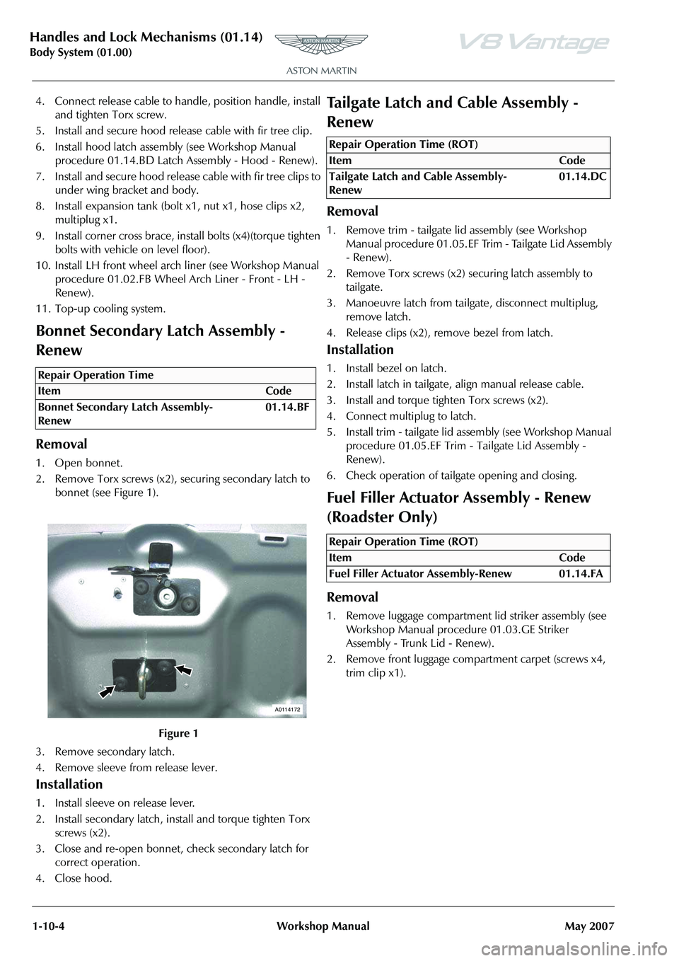
2. Remove Torx screws (x2), securing secondary latch to bonnet (see Figure 1).
3. Remove secondary latch.
4. Remove sleeve from release lever.
Installation
1. Install sleeve on release lever.
2. Install secondary latch, install and torque tighten Torx screws (x2).
3. Close and re-open bonnet, check secondary latch for correct operation.
4. Close hood.
Tailgate Latch and Cable Assembly -
Renew
Removal
1. Remove trim - tailgate lid assembly (see Workshop Manual procedure 01.05.EF Trim - Tailgate Lid Assembly
- Renew).
2. Remove Torx screws (x2) securing latch assembly to
tailgate.
3. Manoeuvre latch from tailgate, disconnect multiplug, remove latch.
4. Release clips (x2), remove bezel from latch.
Installation
1. Install bezel on latch.
2. Install latch in tailgate, align manual release cable.
3. Install and torque tighten Torx screws (x2).
4. Connect multiplug to latch.
5. Install trim - tailgate lid assembly (see Workshop Manual procedure 01.05.EF Trim - Tailgate Lid Assembly -
Renew).
6. Check operation of tailgate opening and closing.
Fuel Filler Actuator Assembly - Renew
(Roadster Only)
Removal
1. Remove luggage compartment lid striker assembly (see Workshop Manual procedure 01.03.GE Striker
Assembly - Trunk Lid - Renew).
2. Remove front luggage compartment carpet (screws x4, trim clip x1).
Repair Operation Time
ItemCode
Bonnet Secondary Latch Assembly-
Renew 01.14.BF
Figure 1
A0114172
Repair Operation Time (ROT)
ItemCode
Tailgate Latch and Cable Assembly-
Renew 01.14.DC
Repair Operation Time (ROT)
ItemCode
Fuel Filler Actuator Assembly-Renew 01.14.FA