relay ASTON MARTIN V8 VANTAGE 2010 User Guide
[x] Cancel search | Manufacturer: ASTON MARTIN, Model Year: 2010, Model line: V8 VANTAGE, Model: ASTON MARTIN V8 VANTAGE 2010Pages: 947, PDF Size: 43.21 MB
Page 693 of 947
Wiring and Circuit Protection (18.01)
Electric Distribution/E lectronic Control (18.00)
18-1-4 Workshop Manual May 2007
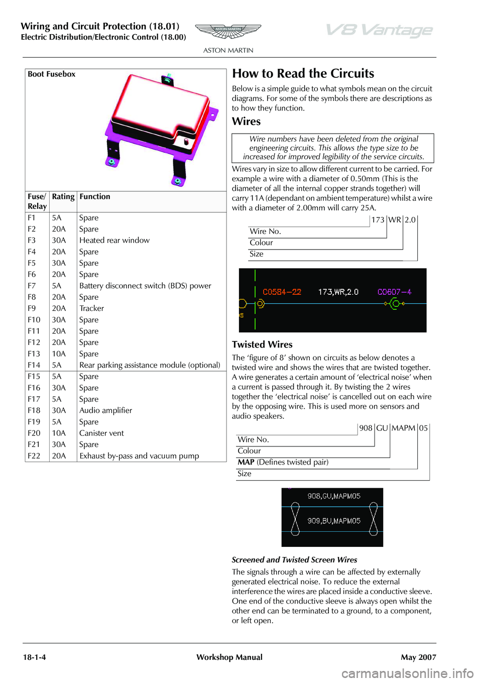
How to Read the Circuits
Below is a simple guide to what symbols mean on the circuit
diagrams. For some of the symbols there are descriptions as
to how they function.
Wires
Wires vary in size to allow diffe rent current to be carried. For
example a wire with a diamet er of 0.50mm (This is the
diameter of all the internal copper strands together) will
carry 11A (dependant on ambient temperature) whilst a wire
with a diameter of 2.00mm will carry 25A.
Twisted Wires
The ‘figure of 8’ shown on circuits as below denotes a
twisted wire and shows the wires that are twisted together.
A wire generates a certain amount of ‘electrical noise’ when
a current is passed through it. By twisting the 2 wires
together the ‘electrical noise’ is cancelled out on each wire
by the opposing wire. This is used more on sensors and
audio speakers.
Screened and Twisted Screen Wires
The signals through a wire can be affected by externally
generated electrical noise. To reduce the external
interference the wires are placed inside a conductive sleeve.
One end of the conductive sleeve is always open whilst the
other end can be terminated to a ground, to a component,
or left open.
Boot Fusebox
Fuse/
RelayRatingFunction
F1 5A Spare
F2 20A Spare
F3 30A Heated rear window
F4 20A Spare
F5 30A Spare
F6 20A Spare
F7 5A Battery disconnect switch (BDS) power
F8 20A Spare
F9 20A Tracker
F10 30A Spare
F11 20A Spare
F12 20A Spare
F13 10A Spare
F14 5A Rear parking assistance module (optional)
F15 5A Spare
F16 30A Spare
F17 5A Spare
F18 30A Audio amplifier
F19 5A Spare
F20 10A Canister vent
F21 30A Spare
F22 20A Exhaust by-pass and vacuum pump
Wire numbers have been deleted from the original
engineering circuits. This al lows the type size to be
increased for improved legibil ity of the service circuits.
173 WR 2.0
Wire No.
Colour
Size
908 GU MAPM 05
Wire No.
Colour
MAP (Defines twisted pair)
Size
Page 697 of 947
Wiring and Circuit Protection (18.01)
Electric Distribution/E lectronic Control (18.00)
18-1-8 Workshop Manual May 2007
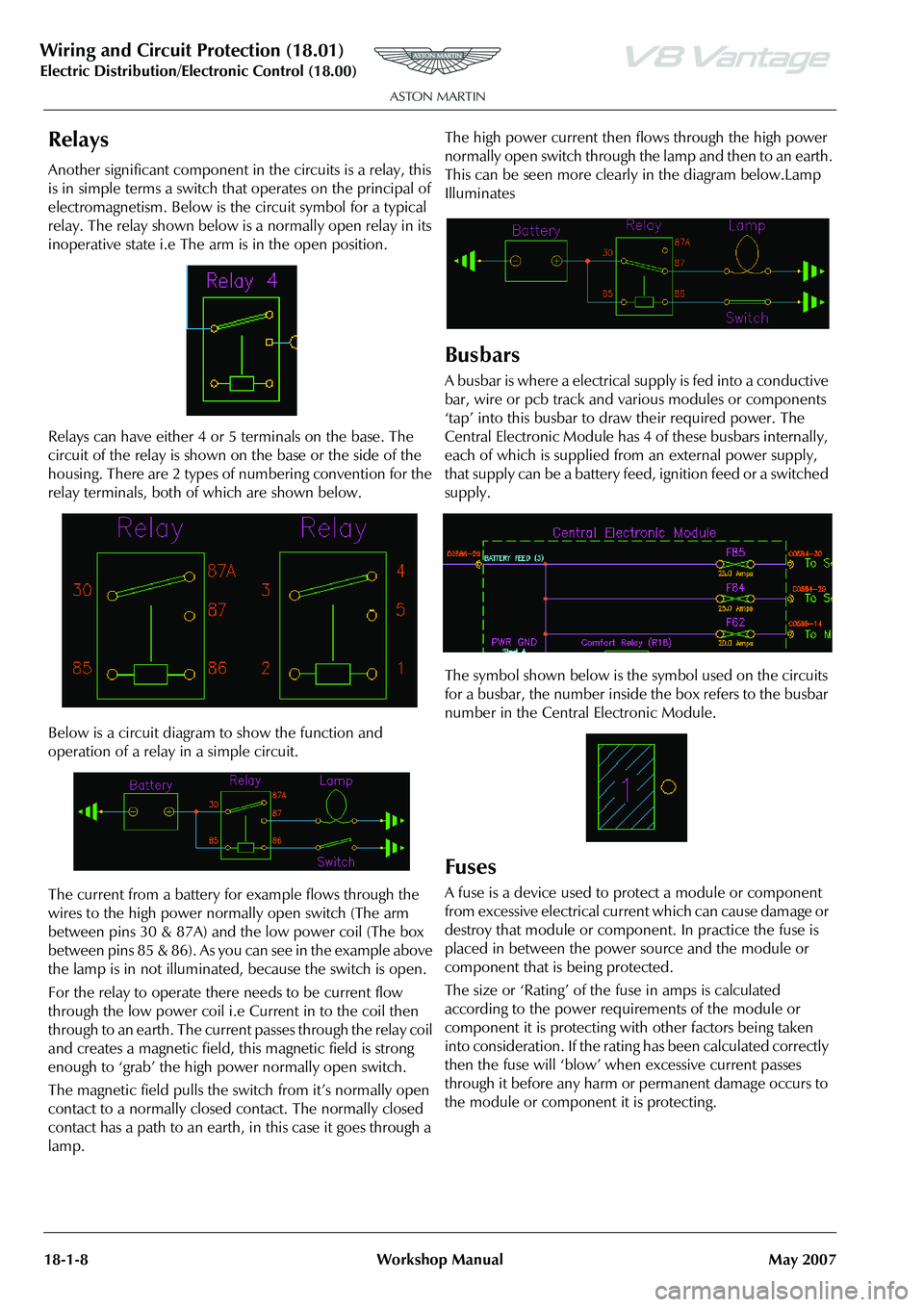
Relays
Another significant component in the circuits is a relay, this
is in simple terms a switch that operates on the principal of
electromagnetism. Below is the circuit symbol for a typical
relay. The relay shown below is a normally open relay in its
inoperative state i.e The arm is in the open position.
Relays can have either 4 or 5 terminals on the base. The
circuit of the relay is shown on the base or the side of the
housing. There are 2 types of numbering convention for the
relay terminals, both of which are shown below.
Below is a circuit diagram to show the function and
operation of a relay in a simple circuit.
The current from a battery for example flows through the
wires to the high power normally open switch (The arm
between pins 30 & 87A) and the low power coil (The box
between pins 85 & 86). As you can see in the example above
the lamp is in not illuminated, because the switch is open.
For the relay to operate there needs to be current flow
through the low power coil i.e Current in to the coil then
through to an earth. The current passes through the relay coil
and creates a magnetic field, this magnetic field is strong
enough to ‘grab’ the high power normally open switch.
The magnetic field pulls the switch from it’s normally open
contact to a normally closed contact. The normally closed
contact has a path to an earth, in this case it goes through a
lamp. The high power current then flows through the high power
normally open switch through the lamp and then to an earth.
This can be seen more clearly in the diagram below.Lamp
Illuminates
Busbars
A busbar is where a electrical
supply is fed into a conductive
bar, wire or pcb track and various modules or components
‘tap’ into this busbar to draw their required power. The
Central Electronic Module has 4 of these busbars internally,
each of which is supplied from an external power supply,
that supply can be a battery feed, ignition feed or a switched
supply.
The symbol shown below is the symbol used on the circuits
for a busbar, the number inside the box refers to the busbar
number in the Central Electronic Module.
Fuses
A fuse is a device used to protect a module or component
from excessive electrical current which can cause damage or
destroy that module or component. In practice the fuse is
placed in between the power source and the module or
component that is being protected.
The size or ‘Rating’ of the fuse in amps is calculated
according to the power requirements of the module or
component it is protecting with other factors being taken
into consideration. If the rating has been calculated correctly
then the fuse will ‘blow’ when excessive current passes
through it before any harm or permanent damage occurs to
the module or component it is protecting.
Page 709 of 947

Wiring and Circuit Protection (18.01)
Electric Distribution/E lectronic Control (18.00)
18-1-20 Workshop Manual May 2007
41. Remove harness/pipe cable ties (see Fig. 22).
42. Disconnect pump multiplug (see Fig. 23).43. Disconnect pump mult
iplug (see Fig. 24).
44. Remove pump relays.
45. Remove end cover (locating tabs x2).
46. Disconnect pump lucar conne ctors (x2) (see Fig. 25).
47. Remove harness from vehicle.
Installation
1. Install harness to approximate route on vehicle.
2. Connect pump lucar connectors.
3. Install pump end cover.
4. Connect pump multiplugs (x2).
5. Install pump relays (x2).
6. Install pump casing and secure velcro.
7. Install harness/pipe cable ties.
8. Install motor and casing under tonneau onto location posts.
9. Install cylinder pivot bracket and connect cylinder to bracket.
Fig. 22
Fig. 23
Fig. 24
Fig. 25
Page 820 of 947

Electronics Training Programme
INPUTS
The Bluetooth system relies on a number of signals it receives either from the car (via hard wiring) or
the users phone (via wireless Bluetooth communication network).
The Bluetooth system will only function if the us ers mobile phone has Bluetooth enabled and it is
‘paired’ to the car. For more information refer to the user’s guide for your mobile phone.
V8 Vantage Power Supplies
Description Supplied From Source Protection
Wakeup signal Central Electronic Module Comfort Relay F68 (5 Amp)
Power supply 1 Central Electronic Module Interior Lights Relay F46 (5Amp)
Power supply 2 Central Electronic Module Interior Lights Relay F46 (5Amp)
DB9 Power Supplies
Description Supplied From Source Protection
Wakeup signal Central Electronic Module Comfort Relay F69 (5 Amp)
Power supply 1 Central Electronic Module Interior Lights Relay F46 (5Amp)
Power supply 2 Central Electronic Module Interior Lights Relay F46 (5Amp)
V8 Vantage Signal Inputs
Input Description Signal Characteristic
MIC In Input signal from microphone Varying current signal direct from microphone
Keypad Steering wheel controls input Variable resistance to earth signal
DB9 Signal Inputs
Input Description Signal Characteristic
MIC In + Input signal from microphone Varying current signal supplied via amplifier
MIC In - Input signal from microphone Varying current signal supplied via amplifier
Keypad Steering wheel controls inpu t Variable resistance to earth
Screens
Some of the signals in and out of the Bluetooth modu le require screening to avoid interference being
picked up. A signal screen is a single wire running along side t he signal wire(s) which will absorb
electro magnetic interference (EMI).
The Bluetooth module on the V8 Vantage features only one screen so as to protect the signal from the
microphone. This screen wire is simply an earth but it is also used as a datum from which to reference
the microphone signal.
The Bluetooth module used on DB9’s features two screens. One is as on the V8 Vantage but is used
only as a screen (because the microphone signal from the amplifie r has two signal wires) and no
datum is required. The second screen on the module is used to screen the ‘Lineout’ signals to the
amplifier. As with the microphone scr een this wire is connected to earth.
15
Page 836 of 947
Electronics Training Programme
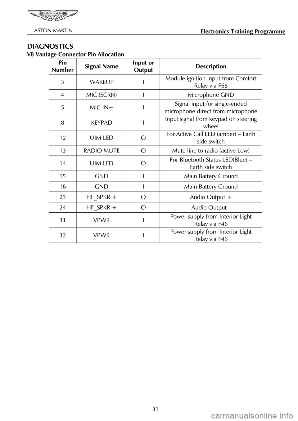
DIAGNOSTICS
V8 Vantage Connector Pin Allocation
Pin
Number Signal Name Input or
Output Description
3 WAKEUP I Module ignition input from Comfort
Relay via F68
4 MIC (SCRN) I Microphone GND
5 MIC IN+ I Signal input for single-ended
microphone direct from microphone
8 KEYPAD I Input signal from keypad on steering wheel
12 UIM LED O For Active Call LED (amber) – Earth
side switch
13 RADIO MUTE O Mute line to radio (active Low)
14 UIM LED O For Bluetooth Status LED(Blue) – Earth side switch
15 GND I Main Battery Ground
16 GND I Main Battery Ground
23 HF_SPKR + O Audio Output +
24 HF_SPKR + O Audio Output -
31 VPWR I Power supply from Interior Light Relay via F46
32 VPWR I Power supply from Interior Light Relay via F46
31
Page 837 of 947
Electronics Training Programme
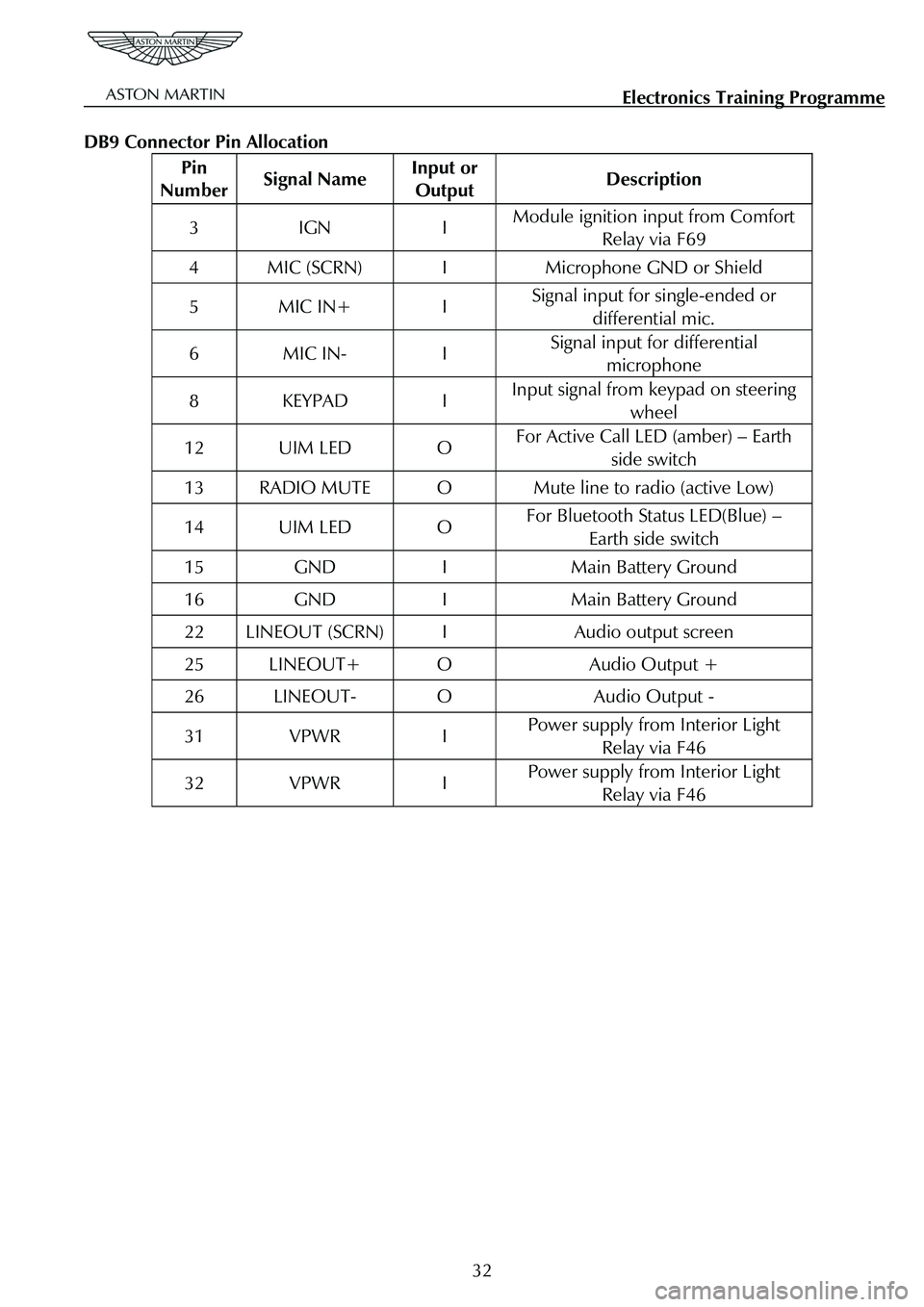
DB9 Connector Pin Allocation
Pin
Number Signal Name Input or
Output Description
3 IGN I Module ignition input from Comfort
Relay via F69
4 MIC (SCRN) I Microphone GND or Shield
5 MIC IN+ I Signal input for single-ended or
differential mic.
6 MIC IN- I Signal input for differential microphone
8 KEYPAD I Input signal from keypad on steering
wheel
12 UIM LED O For Active Call LED (amber) – Earth side switch
13 RADIO MUTE O Mute line to radio (active Low)
14 UIM LED O For Bluetooth Status LED(Blue) – Earth side switch
15 GND I Main Battery Ground
16 GND I Main Battery Ground
22 LINEOUT (SCRN) I Audio output screen
25 LINEOUT+ O Audio Output +
26 LINEOUT- O Audio Output -
31 VPWR I Power supply from Interior Light Relay via F46
32 VPWR I Power supply from Interior Light Relay via F46
32
Page 886 of 947

AML EOBD System Operation Summary
Rory O’Curry Aston Martin Lagonda CONFIDENTIAL 1 May 2009
[email protected] AML EOBD Monitors 07 ROC.doc Page 41 of 43
X P1431 Misfire Monitor Disabled; unable to Learn Trigger Wheel Profile
P1432 Thermostat Heater Control Circuit
P1460 Wide Open Throttle A/C Cut-out Circuit
P1461 A/C Pressure Sensor Circuit High Input
P1462 A/C Pressure Sensor Circuit Low Input
P1463 A/C Pressure Sensor Insufficient Pressure Change
P1464 A/C Demand Out of Self Test Range
P1500 Vehicle Speed Sensor
P1501 Vehicle Speed Sensor Out of Self Test Range
P1549 Intake Manifold Communica tion Control Circuit (Bank 1)
P1572 Brake system input failure (BLS failed then BPS failed)
P1610 Interactive Reprogramming Code – Replace Module
P1611 Interactive Reprogramming Code – Diagnose Further
P1615 Interactive Reprogramming Code – Erase Error
P1616 Interactive Reprogramming Code – Erase Error, Low Voltage
P1617 Interactive Reprogramming Code – Block Program Error
P1618 Interactive Reprogramming Code – Block Program Error, Low Voltage
P1631 Main Relay (Power Hold)
X P1633 Keep Alive Power Voltage too Low
P1635 Tyre/Axle Out of Acceptable Range
P1639 Vehicle Identification (VID) Block Corrupted. Not Programmed
X P1656 CAN Link PCM/PCM Circuit/Network
P1703 Brake switch out of self test range
P1709 Park/Neutral Position Switch Out of Self Test Range
X P2008 Intake Manifold Runner Control Open (Bank 1)
X P2100 Throttle Actuator Control Motor Circuit Open
X P2101 Throttle Actuator Control Motor Circuit Range/Performance
X P2107 Throttle actuator control motor processor
X P2110 Forced limit RPM mode
X P2111 Throttle actuator control system – stuck closed
X P2112 Throttle actuator control system – stuck open
P2121 Pedal position sensor D circuit range/performance
P2122 Pedal position sensor D circuit low input
P2123 Pedal position sensor D circuit high input
P2124 Pedal position sensor D circuit intermittent
P2126 Pedal position sensor E circuit range/performance
P2127 Pedal position sensor E circuit low input
P2128 Pedal position sensor E circuit high input
P2129 Pedal position sensor E circuit intermittent
P2135 Throttle position sensor A/B voltage correlation
P2138 Pedal position sensor D/E voltage correlation
X P2195 Lack of Heated Oxygen Sensor (Bank 1, Sensor 1) Switches, Sensor Indicates Lean
X P2196 Lack of Heated Oxygen Sensor (Bank 2, Sensor 1) Switches, Sensor Indicates Lean
X P2197 Lack of Heated Oxygen Sensor (Bank 1, Sensor 1) Switches, Sensor Indicates Rich
X P2198 Lack of Heated Oxygen Sensor (Bank 2, Sensor 1) Switches, Sensor Indicates Rich
Note.
X MIL codes
* Can be non-mil if below EOBD threshold.
Page 892 of 947
Aston Martin V8 Vantage 2009 MY EOBD DocumentationAston Martin/Ford Confidential
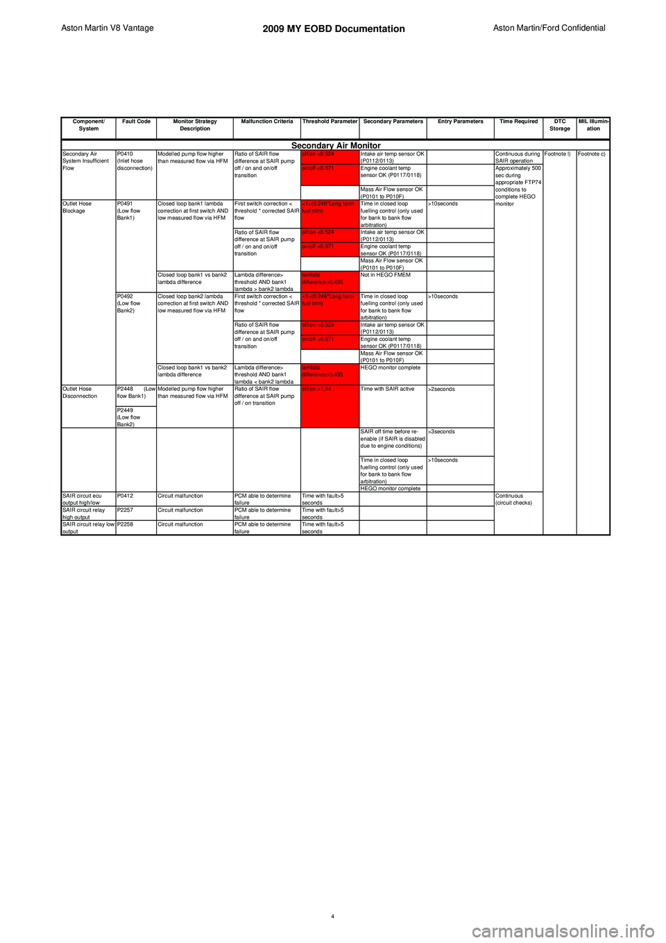
Component/ System Fault Code Monitor Strategy
Description Malfunction Criteria Threshold Parameter Secondary Parameters Entry Parameters Time Required DTC
StorageMIL Illumin-
ation
off/on <0.524 Intake air temp sensor OK (P0112/0113) Continuous during
SAIR operation
on/off <0.671 Engine coolant temp sensor OK (P0117/0118)
Mass Air Flow sensor OK
(P0101 to P010F)
First switch correction <
threshold * corrected SAIR
flow <1+(0.246*Long term
fuel trim)
Time in closed loop
fuelling control (only used
for bank to bank flow
arbitration) >10seconds
off/on <0.524 Intake air temp sensor OK (P0112/0113)
on/off <0.671 Engine coolant temp sensor OK (P0117/0118)
Mass Air Flow sensor OK
(P0101 to P010F)
Closed loop bank1 vs bank2
lambda difference Lambda difference>
threshold AND bank1
lambda > bank2 lambdalambda
difference>0.435
Not in HEGO FMEM
First switch correction <
threshold * corrected SAIR
flow <1+(0.246*Long term
fuel trim)
Time in closed loop
fuelling control (only used
for bank to bank flow
arbitration) >10seconds
off/on <0.524 Intake air temp sensor OK (P0112/0113)
on/off <0.671 Engine coolant temp sensor OK (P0117/0118)
Mass Air Flow sensor OK
(P0101 to P010F)
Closed loop bank1 vs bank2
lambda difference Lambda difference>
threshold AND bank1
lambda < bank2 lambdalambda
difference>0.435
HEGO monitor complete
P2448 (Low
flow Bank1)
P2449
(Low flow
Bank2) SAIR off time before re-
enable (if SAIR is disabled
due to engine conditions)>3seconds
Time in closed loop
fuelling control (only used
for bank to bank flow
arbitration) >10seconds
HEGO monitor complete
SAIR circuit ecu
output high/low P0412 Circuit malfunction
PCM able to determine
failure Time with fault>5
seconds
SAIR circuit relay
high output P2257 Circuit malfunction
PCM able to determine
failure Time with fault>5
seconds
SAIR circuit relay low
output P2258 Circuit malfunction
PCM able to determine
failure Time with fault>5
seconds
Ratio of SAIR flow
difference at SAIR pump
off / on and on/off
transition
Modelled pump flow higher
than measured flow via HFM
Ratio of SAIR flow
difference at SAIR pump
off / on and on/off
transition
Ratio of SAIR flow
difference at SAIR pump
off / on and on/off
transition
>2secondsFootnote c)
Approximately 500
sec during
appropriate FTP74
conditions to
complete HEGO
monitorSecondary Air Monitor
Modelled pump flow higher
than measured flow via HFM Ratio of SAIR flow
difference at SAIR pump
off / on transitionoff/on >1.44
Outlet Hose
Disconnection Footnote l)
Continuous
(circuit checks)
Outlet Hose
Blockage
P0492
(Low flow
Bank2)
P0410
(Inlet hose
disconnection)
Secondary Air
System Insufficient
Flow
Closed loop bank1 lambda
correction at first switch AND
low measured flow via HFM
Closed loop bank2 lambda
correction at first switch AND
low measured flow via HFM
P0491
(Low flow
Bank1)
Time with SAIR active
4
Page 909 of 947
Aston Martin V8 Vantage2009MY OBDII Documentation 4.7L Aston Martin Confidential
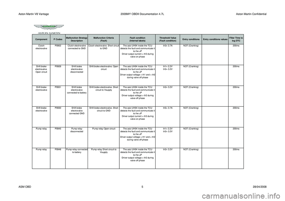
Component P CodesMalfunction Strategy
Description Malfunction Criteria
(Fault) Fault condition
(Internal labels) Threshold Value
(Fault condition) Entry conditions Entry conditions values Filter Time to
log DTCClutch
electrovalve P0902 Clutch electrovalve
connected to GND Clutch electrovalve. Short circuit
to GND The asic UH04 inside the TCU
detects the fault and communicate it to the uP
Driver output current > th3 during valve on phase th3= 3.7A
NOT (Cranking) 200ms
Shift brake
electrovalve. Open circuit P0928 Shift brake
electrovalve
disconnected Shift brake electrovalve. Open
circuit The asic UH04 inside the TCU
detects the fault and communicate it to the uP
Driver output voltage > th1 and < th2 during valve off phase th1= 2.2V
th2= 3.2V
NOT (Cranking)
200ms
Shift brake
electrovalve P0931 Shift brake
electrovalve
connected to battery Shift brake electrovalve. Short
circuit to Vsupply The asic UH04 inside the TCU
detects the fault and communicate it to the uP
Driver output voltage > th2 during valve off phase th2= 3.2V
NOT (Cranking) 200ms
Shift brake
electrovalve P0930 Shift brake
electrovalve
connected GND Shift brake electrovalve. Short
circuit to GND The asic UH04 inside the TCU
detects the fault and communicate it to the uP
Driver output current > th3 during valve on phase th3= 3.7A
NOT (Cranking) 200ms
Pump relay P0945 Pump relay disconnectedPump relay Open circuit The asic UH04 inside the TCU
detects the fault and communicate it to the uP
Driver output voltage > th1 and < th2 during valve off phase th1= 2.2V
th2= 3.2V
NOT (Cranking)
200ms
Pump relay P0948 Pump relay connected to batteryPump relay Short circuit to
Vsupply The asic UH04 inside the TCU
detects the fault and communicate it to the uP
Driver output voltage > th2 during valve off phase th2= 3.2V
NOT (Cranking) 200ms
ASM OBD 528/04/2008
Page 910 of 947

Aston Martin V8 Vantage2009MY OBDII Documentation 4.7L Aston Martin Confidential
Component P CodesMalfunction Strategy
Description Malfunction Criteria
(Fault) Fault condition
(Internal labels) Threshold Value
(Fault condition) Entry conditions Entry conditions values Filter Time to
log DTCPump relay P0947 Pump relay connected GNDPump relay Short circuit to GND The asic UH04 inside the TCU
detects the fault and communicate it to the uP
Driver output current > th3 during valve on phase th3= 3.7A
NOT (Cranking) 200ms
Clutch system P186D Clutch or actuator or valve damagedClutch not opening before gear
shifting Clutch not open in a timeout timeout = 500ms (Gear shifting in
progress) AND
(Clutch opening
Gear Box system P1734 Mechanical or hydraulic problemGear Box. Disengage failed
(mechanical causes) Gear not disengaged in a timeout timeout = 500ms (Gear shifting phase)
AND (disengage phase)
Gear Box system P1701 Mechanical or hydraulic problemGear Box. Wrong gear
engagement The gear which is going to be
engaged is not the requested one (Gear shifting phase)
Hydraulic circuit P0868 Hydraulic leakage Hydraulic circuit. Pressure low Comparison between sensor pressure signal and threshold = f(oil temperature)
pressure < th Th= 25 bar @ -30°C
Th= 40 bar @120°C linear interpolation (Engine ON) AND
NOT (cranking) 200ms
Power grounds P1710 Power grounds. Disconnection both ground pins Power grounds. Disconnection
both ground pins The diagnosis is based on the batter
y
voltage modification during the
activation of the clutch electrovalve. Ubatt < Ubatt0 - DltUbatt Ubatt0 = Ubatt before
starting the testDltUbatt = 2,5V Wake-up phase
ASM OBD
628/04/2008