open hood ASTON MARTIN V8 VANTAGE 2010 Workshop Manual
[x] Cancel search | Manufacturer: ASTON MARTIN, Model Year: 2010, Model line: V8 VANTAGE, Model: ASTON MARTIN V8 VANTAGE 2010Pages: 947, PDF Size: 43.21 MB
Page 14 of 947
1-1-2 Workshop Manual Issue 5, January 2010
RH/LH Seat Switchpack Assembly - Renew...........7-13
Lumbar Pump for the Front Seat (From 08MY)
- Remove and Install.............................................7-13
Lumbar Valve for the Front Seat (From 08MY)
- Remove and Install.............................................7-14
Lumbar Bladder for the Front Seat (From 08MY)
- Remove and Install.............................................7-14
Glass, Frame and Mechanism (01.11) .................. 1-8-1 Description .............................................................8-1 Frameless doors......................................................8-1
Specifications .........................................................8-1
Maintenance ...........................................................8-1 Glass Regulator - Renew .........................................8-1
RH/LH Door Glass - Renew ....................................8-2
Door Glass - Adjust/Reset .......................................8-3
Front Windshield - Renew ......................................8-3
Rear Windshield - Renew .......................................8-4
Quarter Window Glass - Renew .............................8-6
Passenger Window Lift Switch - Renew ..................8-6
Driver Window Lift Switch - Renew........................8-7
Instrument Panel (IP) (01.12)................................ 1-9-1 Specifications ..........................................................9-1
Maintenance ...........................................................9-1 Instrument Panel - Renew ......................................9-1
Airbag Panel and Door Assembly - Renew ..............9-6
Glovebox Assembly - Renew ..................................9-6
Instrument Centre Panel Asse mbly - Renew............9-7
Knee Protector - Renew .........................................9-7
Instrument Panel As sembly - Renew .......................9-7
Cluster Bezel Panel - Renew .................................9-10
Driver Panel Assembly - Renew ............................9-10
Instrument Panel Bezel A ssembly (With Sat. Nav.)
- Renew ...............................................................9-11
Instrument Panel Bezel Assembly
(Without Sat. Nav.) - Renew .................................9-11
Rear Console Panel Assembly - Renew .................9-12
Armrest Pad Assembly - Renew ............................9-13
Console Panel Assembly - Renew .........................9-13
RH/LH Rear Console Pa nel Assembly - Renew
(Roadster Only) ....................................................9-13
Centre Console Panel - Remove and Install
(Coupe Only) .......................................................9-15
Centre Console Panel - Remove and Install
(Roadster Only) ....................................................9-19
RH/LH Lower Quarter Panel Assembly - Renew
(Roadster Only) ....................................................9-29
Handles and Lock Mechanisms (01.14) .............. 1-10-1 Description ...........................................................10-1 Vehicle Key/Remote Transmitter...........................10-1
Central Locking System ........................................10-1
Remote Transmitter ..............................................10-1
Fuel Filler Assembly ..............................................10-1
Boot Emergency Release ....... ...............................10-1
Specifications ........................................................10-2
Maintenance .........................................................10-2 Ignition Cylinder Lock - Re new.............................10-2
RH/LH Front Door Latch As sembly - Renew .........10-2
Bonnet Latch Assembly - Renew...........................10-3
Hood Release Cable Assembly - Renew (Roadster Only) .................................................... 10-3
Bonnet Secondary Latch Asse
mbly - Renew ......... 10-4
Tailgate Latch and Cable Assembly - Renew ......... 10-4
Fuel Filler Actuator Assembly - Renew
(Roadster Only) .................................................... 10-4
Fuel Filler Release Cable - Renew (Roadster Only) 10-5
Fuel Flap Release Switch - Renew ........................ 10-6
RH/LH Tonneau Latch Motor - Renew
(Roadster Only) .................................................... 10-7
RH/LH Tonneau Latch - Renew (Roadster Only) ... 10-7
RH/LH Tonneau Cover Striker Assembly
- Renew (Roadster Only) ...................................... 10-8
Tailgate Latch Assembly-Renew (Roadster Only) ... 10-8
Wipers and Washer System (01.16) ....................1-11-1 Headlamp Washing .............................................. 11-1
Specifications ........................................................ 11-2
Maintenance ......................................................... 11-2 Windscreen Wiper Motor As sembly - Renew ....... 11-2
Wiper Linkage Assembly - Renew ........................ 11-2
Windshield Wash Tube - Renew .......................... 11-2
Windscreen Reservoir and Motor Assembly
- Remove and Install ............................................ 11-3
Low Level Water Sensor - Remove and Install ...... 11-4
Headlamp Wash Motor and Pump Assembly
- Renew ............................................................... 11-5
Headlamp Wash Tube Assembly - Renew ............ 11-5
Washer Fluid Reservoir - Renew........................... 11-6
Convertible Roof and Roof Opening Subsystem
(01.17)..................................................................1-12-1 System Description .............................................. 12-1
Maintenance ......................................................... 12-2 Hood Assembly-Renew ........................................ 12-2
Canopy Cover - Renew ........................................ 12-5
Header Latch Motor - Renew ............................... 12-9
Hydraulic Main Actuator Cy linder - Renew .......... 12-9
Hydraulic Tensrod Cylinder - Renew .................. 12-10
Hydraulic Tonneau Cylinder - Renew................. 12-11
Convertible Top ECU - Renew ........................... 12-13
Hydraulic Pump - Renew ................................... 12-13
Hydraulic Lock Valve - Renew............................ 12-16
RH/LH Front Cantrail Seal - Spare Part
- Renew ............................................................. 12-18
RH/LH Front Cantrail Seal Spare Part Kit
- Renew ............................................................. 12-18
RH/LH Middle Cantrail Seal Spare Part
- Renew ............................................................. 12-18
RH/LH Middle Cantrail Seal Spare Part Kit
- Renew ............................................................. 12-19
Rear Seal Spare Part Assembly Kit - Renew ......... 12-20
LH Fully Automatic Latching Kit - Renew............ 12-21
RH Fully Automatic Latching Kit - Renew ........... 12-22
Convertible Roof Hydraulic Pump
- Check Fluid Level ............................................ 12-23
Cantrail Cover Trim - Renew .............................. 12-25
B-Post Trim Cover - Renew ................................ 12-25
Tonneau Cover - Renew .................................... 12-27
LH Front Main Hydraulic Cylinder Pipe
- Renew ............................................................. 12-29
LH Rear Main Hydraulic Cylinder Pipe
Page 40 of 947
Body Closures (01.03)
Body System (01.00)1-3-14 Workshop Manual May 2007
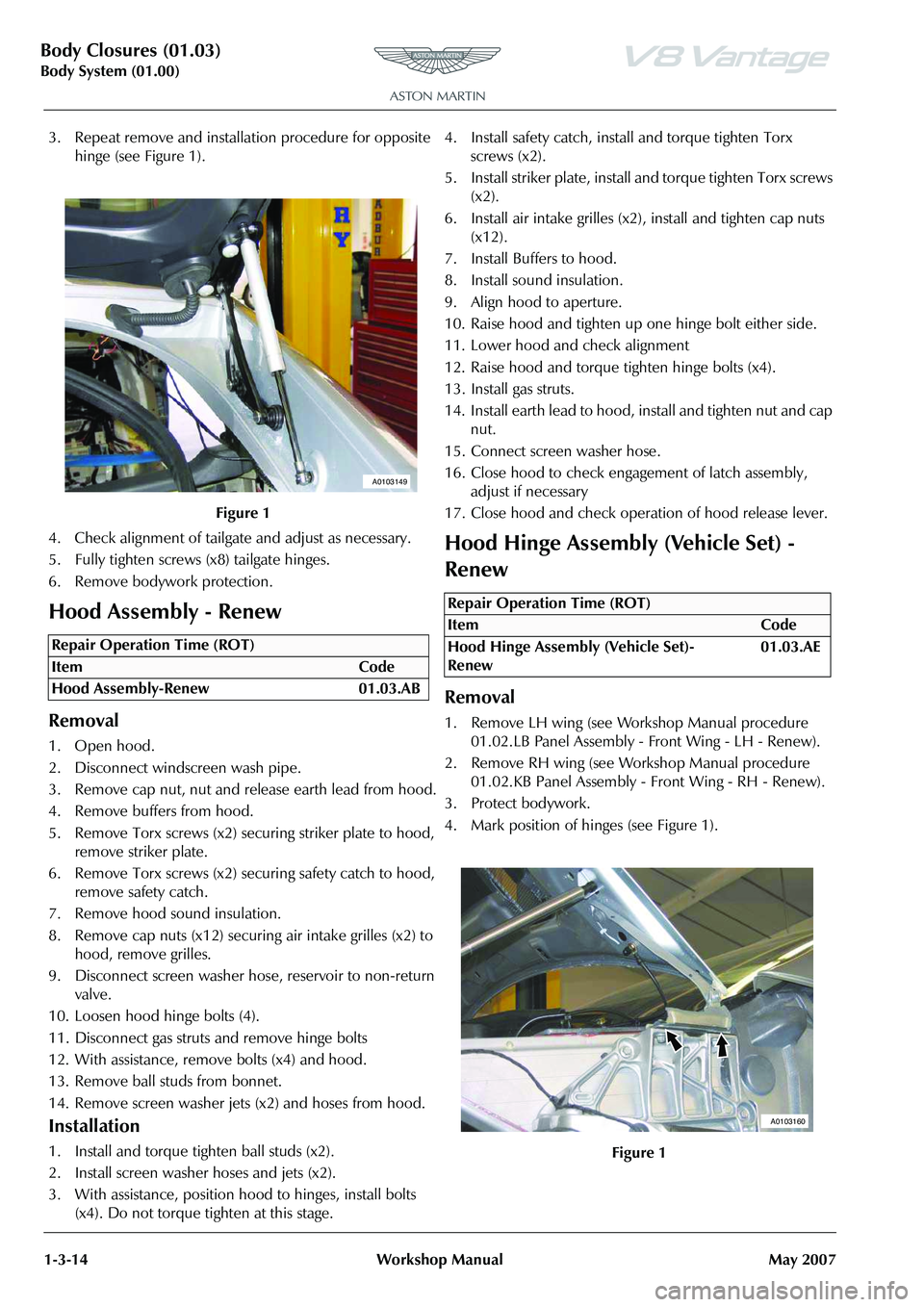
3. Repeat remove and installa tion procedure for opposite
hinge (see Figure 1).
4. Check alignment of tailgate and adjust as necessary.
5. Fully tighten screws (x8) tailgate hinges.
6. Remove bodywork protection.
Hood Assembly - Renew
Removal
1. Open hood.
2. Disconnect windscreen wash pipe.
3. Remove cap nut, nut and release earth lead from hood.
4. Remove buffers from hood.
5. Remove Torx screws (x2) se curing striker plate to hood,
remove striker plate.
6. Remove Torx screws (x2) se curing safety catch to hood,
remove safety catch.
7. Remove hood sound insulation.
8. Remove cap nuts (x12) securing air intake grilles (x2) to
hood, remove grilles.
9. Disconnect screen washer hos e, reservoir to non-return
valve.
10. Loosen hood hinge bolts (4).
11. Disconnect gas struts and remove hinge bolts
12. With assistance, remove bolts (x4) and hood.
13. Remove ball studs from bonnet.
14. Remove screen washer jets (x2) and hoses from hood.
Installation
1. Install and torque tighten ball studs (x2).
2. Install screen washer hoses and jets (x2).
3. With assistance, position hood to hinges, install bolts
(x4). Do not torque tighten at this stage. 4. Install safety catch, install and torque tighten Torx
screws (x2).
5. Install striker plate, install and torque tighten Torx screws (x2).
6. Install air intake grilles (x2), install and tighten cap nuts (x12).
7. Install Buffers to hood.
8. Install sound insulation.
9. Align hood to aperture.
10. Raise hood and tighten up one hinge bolt either side.
11. Lower hood and check alignment
12. Raise hood and torque tighten hinge bolts (x4).
13. Install gas struts.
14. Install earth lead to hood, install and tighten nut and cap nut.
15. Connect screen washer hose.
16. Close hood to check enga gement of latch assembly,
adjust if necessary
17. Close hood and check operation of hood release lever.
Hood Hinge Assembly (Vehicle Set) -
Renew
Removal
1. Remove LH wing (see Workshop Manual procedure 01.02.LB Panel Assembly - Front Wing - LH - Renew).
2. Remove RH wing (see Workshop Manual procedure 01.02.KB Panel Assembly - Front Wing - RH - Renew).
3. Protect bodywork.
4. Mark position of hinges (see Figure 1).
Figure 1
Repair Operation Time (ROT)
A0103149
Repair Operation Time (ROT)
ItemCode
Hood Hinge Assembly (Vehicle Set)-
Renew 01.03.AE
Figure 1
A0103160
Page 108 of 947
Instrument Panel (IP) (01.12)
Body System (01.00)1-9-20 Workshop Manual Issue 5, January 2010
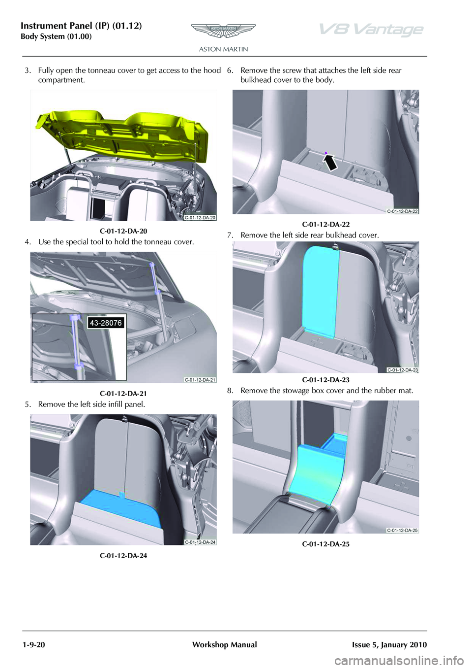
3. Fully open the tonneau cover to get access to the hood compartment.
C-01-12-DA-20
4. Use the special tool to hold the tonneau cover.
C-01-12-DA-21
5. Remove the left side infill panel.
C-01-12-DA-24
6. Remove the screw that attaches the left side rear bulkhead cover to the body.
C-01-12-DA-22
7. Remove the left side rear bulkhead cover.
C-01-12-DA-23
8. Remove the stowage box cover and the rubber mat.
C-01-12-DA-25
Page 124 of 947
Handles and Lock Mechanisms (01.14)
Body System (01.00)1-10-4 Workshop Manual May 2007
4. Connect release cable to hand le, position handle, install
and tighten Torx screw.
5. Install and secure hood release cable with fir tree clip.
6. Install hood latch assembly (see Workshop Manual procedure 01.14.BD Latch Assembly - Hood - Renew).
7. Install and secure hood release cable with fir tree clips to under wing bracket and body.
8. Install expansion tank (bolt x1, nut x1, hose clips x2, multiplug x1.
9. Install corner cross brace, install bolts (x4)(torque tighten bolts with vehicle on level floor).
10. Install LH front wheel arch liner (see Workshop Manual
procedure 01.02.FB Wheel Arch Liner - Front - LH -
Renew).
11. Top-up cooling system.
Bonnet Secondary Latch Assembly -
Renew
Removal
1. Open bonnet.
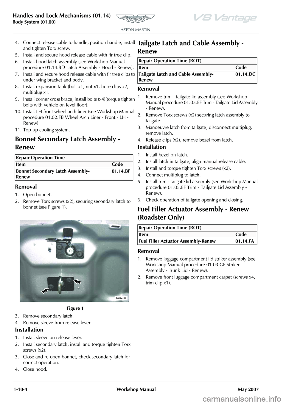
2. Remove Torx screws (x2), securing secondary latch to bonnet (see Figure 1).
3. Remove secondary latch.
4. Remove sleeve from release lever.
Installation
1. Install sleeve on release lever.
2. Install secondary latch, install and torque tighten Torx screws (x2).
3. Close and re-open bonnet, check secondary latch for correct operation.
4. Close hood.
Tailgate Latch and Cable Assembly -
Renew
Removal
1. Remove trim - tailgate lid assembly (see Workshop Manual procedure 01.05.EF Trim - Tailgate Lid Assembly
- Renew).
2. Remove Torx screws (x2) securing latch assembly to
tailgate.
3. Manoeuvre latch from tailgate, disconnect multiplug, remove latch.
4. Release clips (x2), remove bezel from latch.
Installation
1. Install bezel on latch.
2. Install latch in tailgate, align manual release cable.
3. Install and torque tighten Torx screws (x2).
4. Connect multiplug to latch.
5. Install trim - tailgate lid assembly (see Workshop Manual procedure 01.05.EF Trim - Tailgate Lid Assembly -
Renew).
6. Check operation of tailgate opening and closing.
Fuel Filler Actuator Assembly - Renew
(Roadster Only)
Removal
1. Remove luggage compartment lid striker assembly (see Workshop Manual procedure 01.03.GE Striker
Assembly - Trunk Lid - Renew).
2. Remove front luggage compartment carpet (screws x4, trim clip x1).
Repair Operation Time
ItemCode
Bonnet Secondary Latch Assembly-
Renew 01.14.BF
Figure 1
A0114172
Repair Operation Time (ROT)
ItemCode
Tailgate Latch and Cable Assembly-
Renew 01.14.DC
Repair Operation Time (ROT)
ItemCode
Fuel Filler Actuator Assembly-Renew 01.14.FA
Page 133 of 947
Wipers and Washer System (01.16)
Body System (01.00)
Issue 4, November, 2008 Workshop Manual 1-11-3
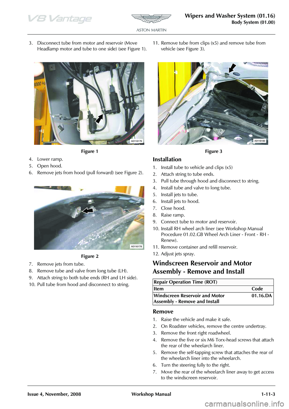
3. Disconnect tube from motor and reservoir (Move Headlamp motor and tube to one side) (see Figure 1).
4. Lower ramp.
5. Open hood.
6. Remove jets from hood (pull forward) (see Figure 2).
7. Remove jets from tube.
8. Remove tube and valve from long tube (LH).
9. Attach string to both tube ends (RH and LH side).
10. Pull tube from hood and disconnect to string. 11. Remove tube from clips (x5) and remove tube from
vehicle (see Figure 3).
Installation
1. Install tube to vehicle and clips (x5)
2. Attach string to tube ends.
3. Pull tube through hood and disconnect to string.
4. Install tube and valve to long tube.
5. Install jets to tube.
6. Install jets to hood.
7. Close hood.
8. Raise ramp.
9. Connect tube to motor and reservoir.
10. Install RH wheel arch liner (see Workshop Manual Procedure 01.02.GB Wheel Arch Liner - Front - RH -
Renew).
11. Remove container and refill reservoir.
12. Adjust jets spray.
Windscreen Reservoir and Motor
Assembly - Remove and Install
Remove
1. Raise the vehicle and make it safe.
2. On Roadster vehicles, re move the centre undertray.
3. Remove the front right roadwheel.
4. Remove the five or six M6 Torx-head screws that attach the rear of the wheelarch liner.
5. Remove the self-tapping screw that attaches the rear of the wheelarch liner into the wheelarch.
6. Turn the steering fully to the right.
7. Move the rear of the wheelarch liner away to get access to the windscreen reservoir.
Figure 1
Figure 2
A0116179
A0116178
Figure 3
Repair Operation Time (ROT)
A0116183
Page 136 of 947
Wipers and Washer System (01.16)
Body System (01.00)1-11-6 Workshop Manual Issue 4,November, 2008
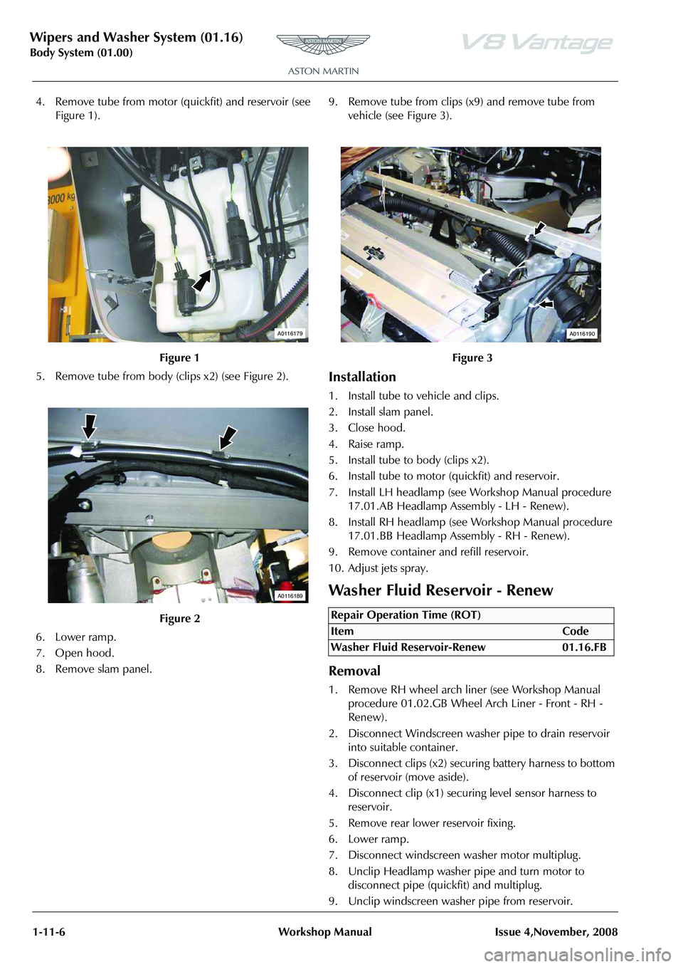
4. Remove tube from motor (quickfit) and reservoir (see Figure 1).
5. Remove tube from body (c lips x2) (see Figure 2).
6. Lower ramp.
7. Open hood.
8. Remove slam panel. 9. Remove tube from clips (x9) and remove tube from
vehicle (see Figure 3).
Installation
1. Install tube to vehicle and clips.
2. Install slam panel.
3. Close hood.
4. Raise ramp.
5. Install tube to body (clips x2).
6. Install tube to motor (quickfit) and reservoir.
7. Install LH headlamp (see Workshop Manual procedure 17.01.AB Headlamp As sembly - LH - Renew).
8. Install RH headlamp (see Workshop Manual procedure
17.01.BB Headlamp Assembly - RH - Renew).
9. Remove container and refill reservoir.
10. Adjust jets spray.
Washer Fluid Reservoir - Renew
Removal
1. Remove RH wheel arch liner (see Workshop Manual procedure 01.02.GB Wheel Arch Liner - Front - RH -
Renew).
2. Disconnect Windscreen wash er pipe to drain reservoir
into suitable container.
3. Disconnect clips (x2) securing battery harness to bottom of reservoir (move aside).
4. Disconnect clip (x1) securi ng level sensor harness to
reservoir.
5. Remove rear lower reservoir fixing.
6. Lower ramp.
7. Disconnect windscreen washer motor multiplug.
8. Unclip Headlamp washer pipe and turn motor to disconnect pipe (quickfit) and multiplug.
9. Unclip windscreen washer pipe from reservoir.
Figure 1
Figure 2
A0116179
A0116189
Figure 3
Repair Operation Time (ROT)
ItemCode
Washer Fluid Reservoir-Renew 01.16.FB
A0116190
Page 140 of 947
Convertible Roof (01.17)
Body System (01.00)1-12-2 Workshop Manual May 2007
Maintenance
Hood Assembly-Renew
Removal
1. Remove Tonneau well liner (see Workshop Manual procedure 01.17.DB Tonneau Well Liner - Renew).
2. Remove Panel assembly body side LH (see Workshop
Manual procedure 01.05.DY Panel Assembly - Bodyside
Trim - Rear - LH - Renew).
3. Remove Panel assembly body side RH (see Workshop Manual procedure 01.05.DX Panel Assembly - Bodyside
Trim - Rear - RH - Renew).
4. Remove Tonneau cover (see Workshop Manual procedure 01.17.CA Cover - Tonneau - Renew).
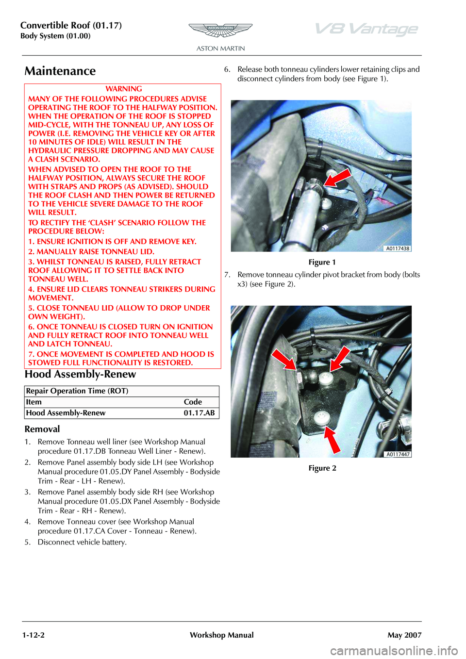
5. Disconnect vehicle battery. 6. Release both tonneau cylinders lower retaining clips and
disconnect cylinders from body (see Figure 1).
7. Remove tonneau cylinder pivot bracket from body (bolts x3) (see Figure 2).
WAR NI NG
MANY OF THE FOLLOWING PROCEDURES ADVISE
OPERATING THE ROOF TO THE HALFWAY POSITION.
WHEN THE OPERATION OF THE ROOF IS STOPPED
MID-CYCLE, WITH THE TO NNEAU UP, ANY LOSS OF
POWER (I.E. REMOVING THE VEHICLE KEY OR AFTER
10 MINUTES OF IDLE) WILL RESULT IN THE
HYDRAULIC PRESSURE DROPPING AND MAY CAUSE
A CLASH SCENARIO.
WHEN ADVISED TO OPEN THE ROOF TO THE
HALFWAY POSITION, ALWA YS SECURE THE ROOF
WITH STRAPS AND PROPS (AS ADVISED). SHOULD
THE ROOF CLASH AND THEN POWER BE RETURNED
TO THE VEHICLE SEVERE DAMAGE TO THE ROOF
WILL RESULT.
TO RECTIFY THE ‘CLASH’ SCENARIO FOLLOW THE
PROCEDURE BELOW:
1. ENSURE IGNITION IS OFF AND REMOVE KEY.
2. MANUALLY RAISE TONNEAU LID.
3. WHILST TONNEAU IS RAISED, FULLY RETRACT
ROOF ALLOWING IT TO SETTLE BACK INTO
TONNEAU WELL.
4. ENSURE LID CLEARS TONNEAU STRIKERS DURING
MOVEMENT.
5. CLOSE TONNEAU LID (ALLOW TO DROP UNDER
OWN WEIGHT).
6. ONCE TONNEAU IS CLOSED TURN ON IGNITION
AND FULLY RETRACT ROOF INTO TONNEAU WELL
AND LATCH TONNEAU.
7. ONCE MOVEMENT IS COMPLETED AND HOOD IS
STOWED FULL FUNCTIONALITY IS RESTORED.
Repair Operation Time (ROT)
Figure 1
Figure 2
Page 143 of 947
Convertible Roof (01.17)
Body System (01.00)
May 2007 Workshop Manual 1-12-5
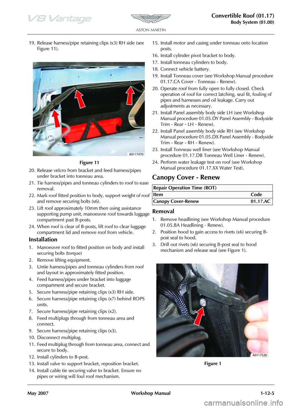
19. Release harness/pipe retaining clips (x3) RH side (see Figure 11).
20. Release velcro from bracket and feed harness/pipes under bracket into tonneau area.
21. Tie harness/pipes and tonneau cylinders to roof to ease removal.
22. Mark roof fitted position to body, support weight of roof and remove securing bolts (x6).
23. Lift roof approximately 10mm then using assistance
supporting pump unit, manoeuvre roof towards luggage
compartment past B-posts.
24. When roof is clear of B-post s, lift roof to clear luggage
compartment lid and remove roof from vehicle.
Installation
1. Manoeuvre roof to fitted position on body and install securing bolts (torque)
2. Remove lifting equipment.
3. Untie harness/pipes and tonneau cylinders from roof and layout in approximately fitted position.
4. Feed harness/pipes under bracket into luggage compartment and secure bracket.
5. Secure harness/pipe retaining clips (x3) RH side.
6. Secure harness/pipe retaining clips (x7) behind ROPS units.
7. Secure harness/pipe retaining clips (x2).
8. Feed multiplugs through from tonneau area and connect.
9. Secure harness/pipe retaining clips (x3).
10. Disconnect multiplug.
11. Feed multiplug through from tonneau area, connect and secure to body.
12. Install cylinders to B-post.
13. Install valve to support bracket, reposition bracket.
14. Install cable tie securing valve to bracket. Ensure no pipes or wiring will foul roof mechanism. 15. Install motor and casing under tonneau onto location
posts.
16. Install cylinder pivot bracket to body.
17. Install tonneau cylinders to body.
18. Connect vehicle battery.
19. Install Tonneau cover (see Workshop Manual procedure 01.17.CA Cover - Tonneau - Renew).
20. Operate roof from fully open to fully closed. Check operation of roof for correct latching, seal fit, fouling of
pipes and harnesses and oil leakage. Carry out
adjustments as necessary.
21. Install Panel assembly bo dy side LH (see Workshop
Manual procedure 01.05.DY Panel Assembly - Bodyside
Trim - Rear - LH - Renew).
22. Install Panel assembly body side RH (see Workshop Manual procedure 01.05.DX Pa nel Assembly - Bodyside
Trim - Rear - RH - Renew).
23. Install Tonneau well line r (see Workshop Manual
procedure 01.17.DB Tonneau Well Liner - Renew).
24. Perform water leakage test on roof (see Workshop Manual procedure 01.17.XX Water Test).
Canopy Cover - Renew
Removal
1. Remove headlining (see Workshop Manual procedure
01.05.BA Headlining - Renew).
2. Position hood to gain access to rivets (x6) securing B- post seal to hood.
3. Drill out rivets (x6) secu ring B-post seal to hood
mechanism and release seal (see Figure 1).
Figure 11
Repair Operation Time (ROT)
Page 147 of 947
Convertible Roof (01.17)
Body System (01.00)
May 2007 Workshop Manual 1-12-9
20. Secure canopy straps to third cross bar using screws.
21. Position hood to gain access to B-post seal fixings.
22. Remove self tapping screws and secure B-post seal to hood mechanism using rivets starting with the lowest
hole first.
23. Restore roof to original position, raise door glass and
check alignment of front seals.
24. Install headlining (see Workshop Manual procedure
01.05.BA Headlining - Renew).
25. Check operation and fit of hood.
Header Latch Motor - Renew
Removal
1. Remove left-hand header latch flex shaft (see Workshop Manual procedure 01.17.EF Flex Shaft - LH - Renew).
2. Remove right-hand header latch flex shaft (see Workshop Manual procedure 01.17.EG Flex Shaft - RH
- Renew).
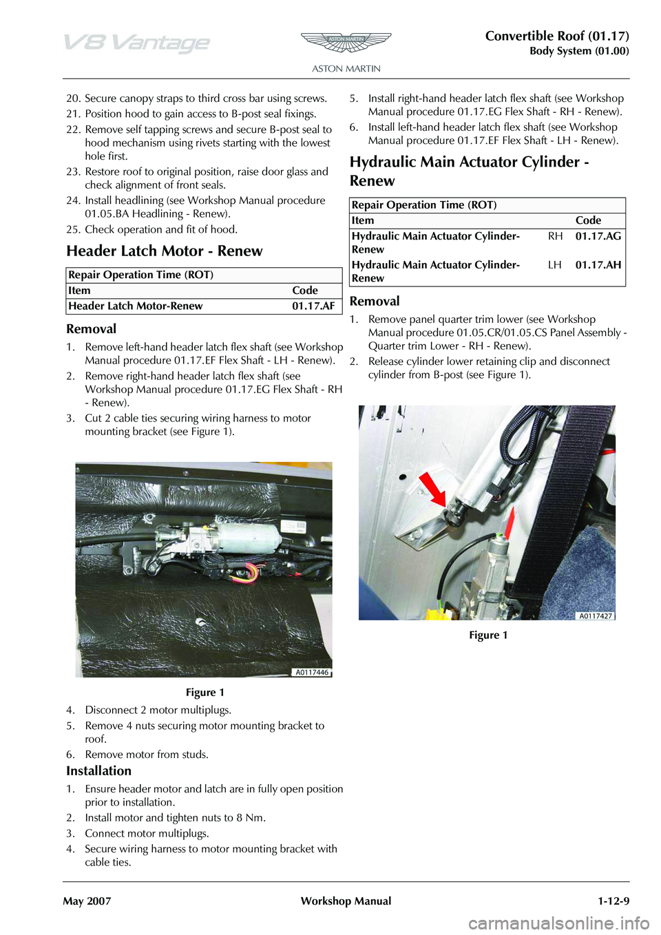
3. Cut 2 cable ties securing wiring harness to motor mounting bracket (see Figure 1).
4. Disconnect 2 motor multiplugs.
5. Remove 4 nuts securing motor mounting bracket to roof.
6. Remove motor from studs.
Installation
1. Ensure header motor and latch are in fully open position prior to installation.
2. Install motor and tighten nuts to 8 Nm.
3. Connect motor multiplugs.
4. Secure wiring harness to motor mounting bracket with cable ties. 5. Install right-hand header la
tch flex shaft (see Workshop
Manual procedure 01.17.EG Flex Shaft - RH - Renew).
6. Install left-hand header latc h flex shaft (see Workshop
Manual procedure 01.17.EF Flex Shaft - LH - Renew).
Hydraulic Main Actuator Cylinder -
Renew
Removal
1. Remove panel quarter trim lower (see Workshop
Manual procedure 01.05.CR/01.05.CS Panel Assembly -
Quarter trim Lower - RH - Renew).
2. Release cylinder lower retaining clip and disconnect cylinder from B-post (see Figure 1).
Repair Operation Time (ROT)
Repair Operation Time (ROT)
Page 167 of 947
Convertible Roof (01.17)
Body System (01.00)
May 2007 Workshop Manual 1-12-29
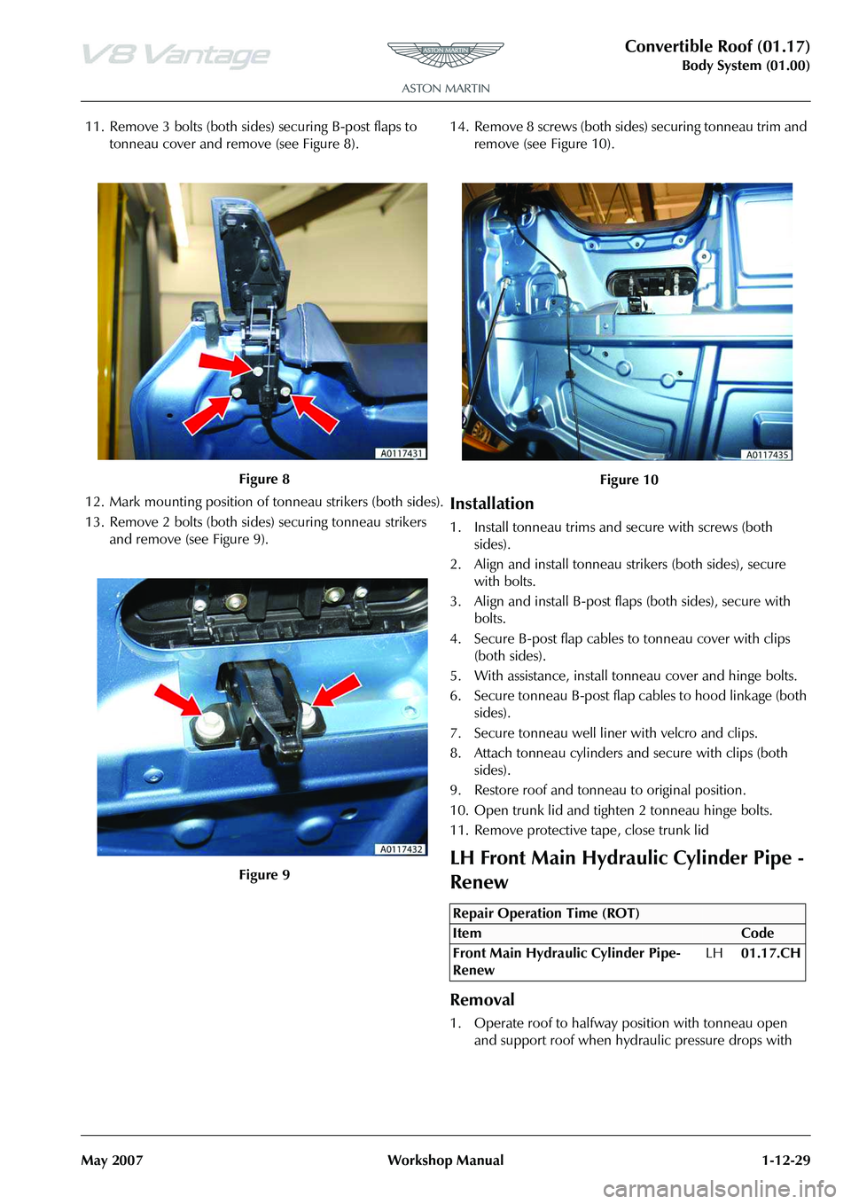
11. Remove 3 bolts (both sides) securing B-post flaps to tonneau cover and remove (see Figure 8).
12. Mark mounting position of tonneau strikers (both sides).
13. Remove 2 bolts (both sides) securing tonneau strikers and remove (see Figure 9). 14. Remove 8 screws (both sides
) securing tonneau trim and
remove (see Figure 10).
Installation
1. Install tonneau trims and secure with screws (both sides).
2. Align and install tonneau st rikers (both sides), secure
with bolts.
3. Align and install B-post flaps (both sides), secure with bolts.
4. Secure B-post flap cables to tonneau cover with clips (both sides).
5. With assistance, install tonneau cover and hinge bolts.
6. Secure tonneau B-post flap cables to hood linkage (both sides).
7. Secure tonneau well liner with velcro and clips.
8. Attach tonneau cylinders and secure with clips (both sides).
9. Restore roof and tonneau to original position.
10. Open trunk lid and tighten 2 tonneau hinge bolts.
11. Remove protective tape, close trunk lid
LH Front Main Hydraulic Cylinder Pipe -
Renew
Removal
1. Operate roof to halfway position with tonneau open and support roof when hydraulic pressure drops with
Figure 8
Figure 9
Figure 10
Repair Operation Time (ROT)