tyres ASTON MARTIN V8 VANTAGE 2010 User Guide
[x] Cancel search | Manufacturer: ASTON MARTIN, Model Year: 2010, Model line: V8 VANTAGE, Model: ASTON MARTIN V8 VANTAGE 2010Pages: 947, PDF Size: 43.21 MB
Page 457 of 947
Road Wheels and Tyres (04.04)
Suspension (04.00)
May 2007 Workshop Manual 4-4-7
Repairs
In view of the high performance capability of the vehicle,
damaged tyres should be renewed and not repaired.
Care of Alloy Road Wheels
Aluminium alloy road wheels are covered with a protective
coating. To prevent corrosion it is essential that this coating
is not damaged. When removing or installing tyres only
equipment utilizing spigot or stud hole clamping must be
used. The equipment must not have any moving parts which
contact the road wheel, and ty re levers must not be used.
To clean road wheels use warm soapy water; stubborn stains
can be removed using a soft brush or by using a proprietary
alloy road wheel cleaner.
Road Wheel Alignment
It is important that correct road wheel alignment be
maintained. Misalignment causes tyre tread to be scrubbed
off laterally because the natural direction of the road wheel
differs from that of the vehicle.
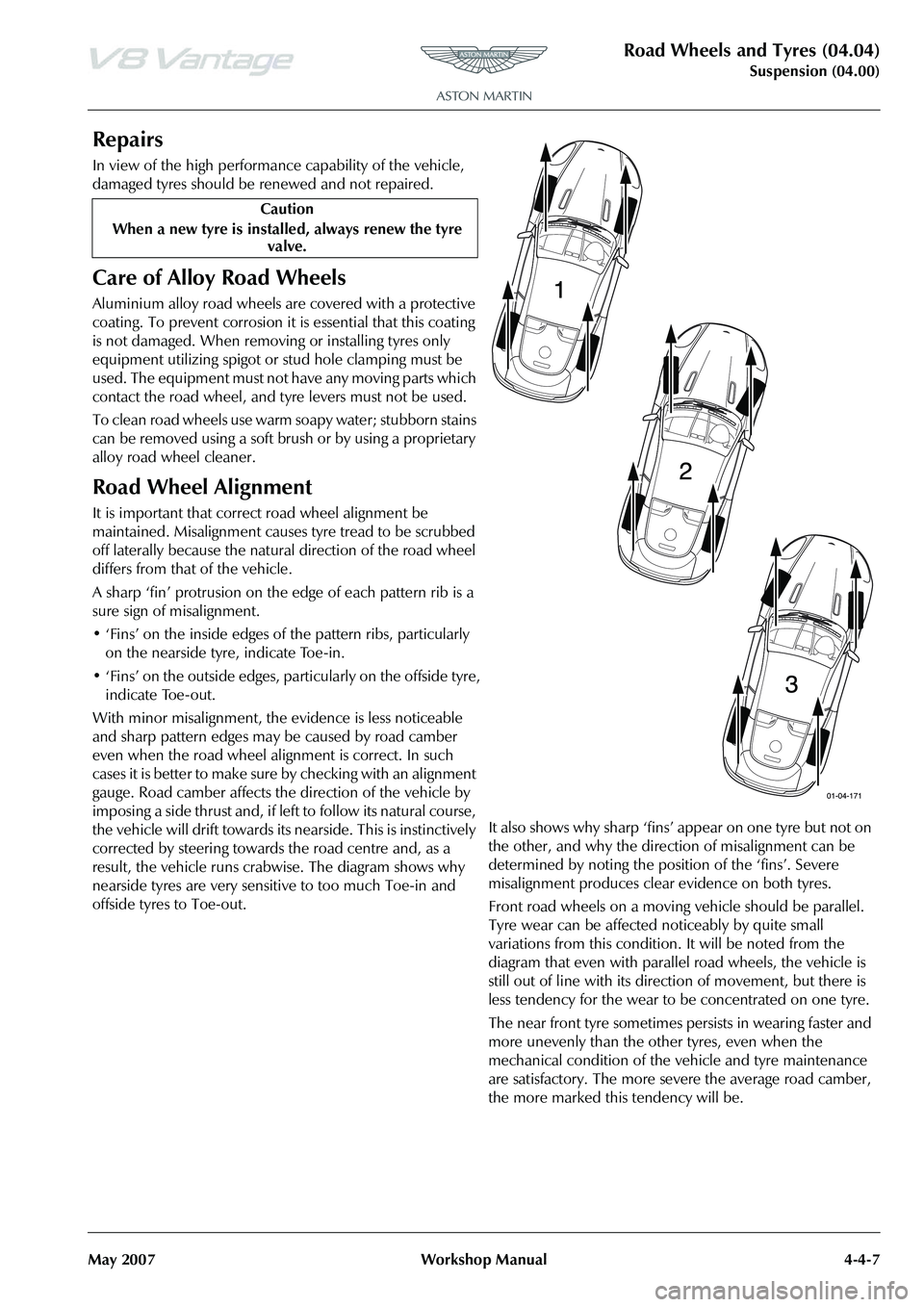
A sharp ‘fin’ protrusion on the edge of each pattern rib is a
sure sign of misalignment.
• ‘Fins’ on the inside edges of the pattern ribs, particularly on the nearside tyre, indicate Toe-in.
• ‘Fins’ on the outside edges, particularly on the offside tyre, indicate Toe-out.
With minor misalignment, the ev idence is less noticeable
and sharp pattern edges may be caused by road camber
even when the road wheel alignment is correct. In such
c a s e s i t i s b e t t e r t o m a k e s u r e b y c h e c k i n g w i t h a n a l i g n m e n t
gauge. Road camber affects the direction of the vehicle by
imposing a side thrus t and , if le ft to follow its natural cou rs e,
the vehicle will drift towards its nearside. This is instinctively
corrected by steering towards the road centre and, as a
result, the vehicle runs crab wise. The diagram shows why
nearside tyres are very sensitive to too much Toe-in and
offside tyres to Toe-out. It also shows why sharp ‘fins’ appear on one tyre but not on
the other, and why the direction of misalignment can be
determined by noting the position of the ‘fins’. Severe
misalignment produces clea
r evidence on both tyres.
Front road wheels on a moving vehicle should be parallel.
Tyre wear can be affected noticeably by quite small
variations from this condition. It will be noted from the
diagram that even with parallel road wheels, the vehicle is
still out of line with its dire ction of movement, but there is
less tendency for the wear to be concentrated on one tyre.
The near front tyre sometimes persists in wearing faster and
more unevenly than the other tyres, even when the
mechanical condition of the vehicle and tyre maintenance
are satisfactory. The more severe the average road camber,
the more marked this tendency will be.
Caution
When a new tyre is installe d, always renew the tyre
valve.
Page 458 of 947
Road Wheels and Tyres (04.04)
Suspension (04.00)4-4-8 Workshop Manual May 2007
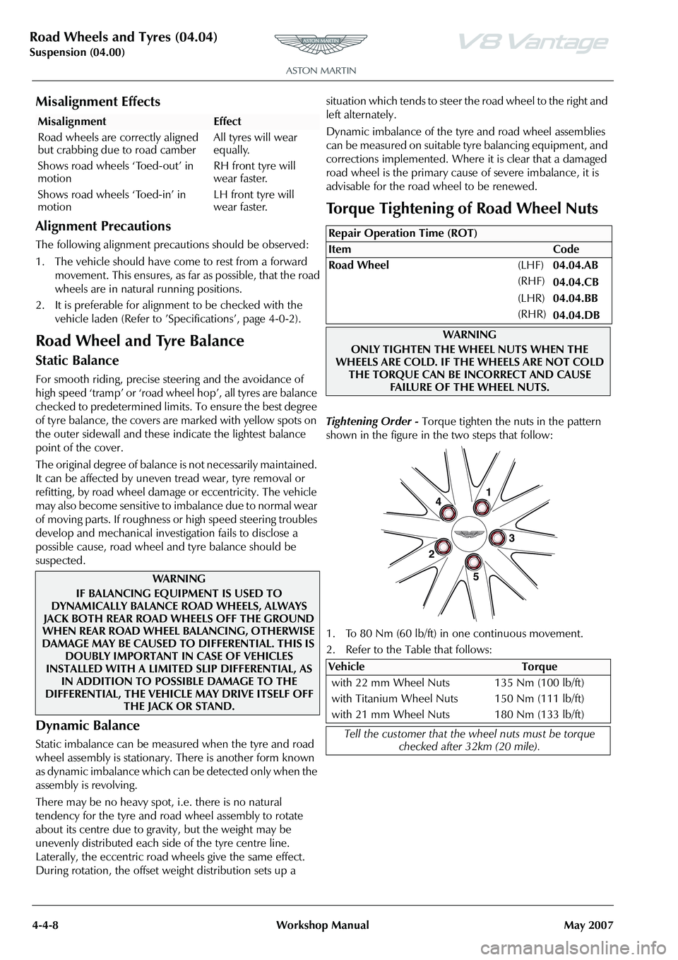
Misalignment Effects
Alignment Precautions
The following alignment precau tions should be observed:
1. The vehicle should have come to rest from a forward movement. This ensures, as fa r as possible, that the road
wheels are in natura l running positions.
2. It is preferable for alignment to be checked with the vehicle laden (Refer to
Page 459 of 947
Road Wheels and Tyres (04.04)
Suspension (04.00)
May 2007 Workshop Manual 4-4-9
Tyre Pressure Sensing (Option)
Tyre pressure sensing monitors the vehicle tyre pressures
and feeds-back this info rmation to the driver.
Each road wheel is installed with a tyre pressure sensing
device which sends tyre pressu re information to a control
unit mounted in the centre, rear wall of the boot.
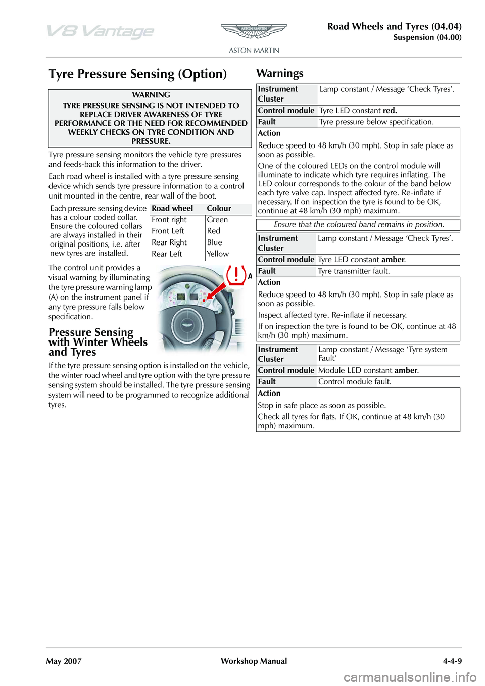
The control unit provides a
visual warning by illuminating
the tyre pressure warning lamp
(A) on the instrument panel if
any tyre pressure falls below
specification.
Pressure Sensing
with Winter Wheels
and Tyres
If the tyre pressure sensing option is installed on the vehicle,
the winter road wheel and tyre option with the tyre pressure
sensing system should be installed. The tyre pressure sensing
system will need to be programmed to recognize additional
tyres.
Wa r n i n g s
WAR NI NG
TYRE PRESSURE SENSING IS NOT INTENDED TO REPLACE DRIVER AWARENESS OF TYRE
PERFORMANCE OR THE NEED FOR RECOMMENDED WEEKLY CHECKS ON TYRE CONDITION AND
PRESSURE.
Each pressure sensing device
has a colour coded collar.
Ensure the coloured collars
are always installed in their
original positions, i.e. after
new tyres are installed.
Road wheelColour
Front right
Front Left
Rear Right
Rear Left Green
Red
Blue
Yellow
Instrument
Cluster
Lamp constant / Message ‘Check Tyres’.
Fault
Tyre pressure below specification.
Action
Reduce speed to 48 km/h (30 mph). Stop in safe place as
soon as possible.
One of the coloured LEDs on the control module will
illuminate to indicate which tyre requires inflating . The
LED colour corresponds to th e colour of the band below
each tyre valve cap. Inspect affected tyre. Re-inflate if
necessary. If on inspection the tyre is found to be OK,
continue at 48 km/h (30 mph) maximum.
Ensure that the coloured band remains in position.
Instrument
Cluster Lamp constant / Message ‘Check Tyres’.
Fault
Tyre transmitter fault.
Action
Reduce speed to 48 km/h (30 mph). Stop in safe place as
soon as possible.
Inspect affected tyre. Re-inflate if necessary.
If on inspection the tyre is found to be OK, continue at 48
km/h (30 mph) maximum.
Instrument
Cluster Lamp constant / Message ‘Tyre system
Fault’
Fault
Control module fault.
Action
Stop in safe place as soon as possible.
Check all tyres for flats. If OK, continue at 48 km/h (30
mph) maximum.
Page 460 of 947
Road Wheels and Tyres (04.04)
Suspension (04.00)4-4-10 Workshop Manual May 2007
Display Unit
The display unit provides additional features when correctly
connected to a previously installed ‘Smartire’ system. The
display unit connects directly to the front of the basic
‘Smartire’ receiver and is powered from the vehicle circuits.
The display will be fully illu minated during use but will go
into ‘Energy Saver’ mode when no activity is detected.
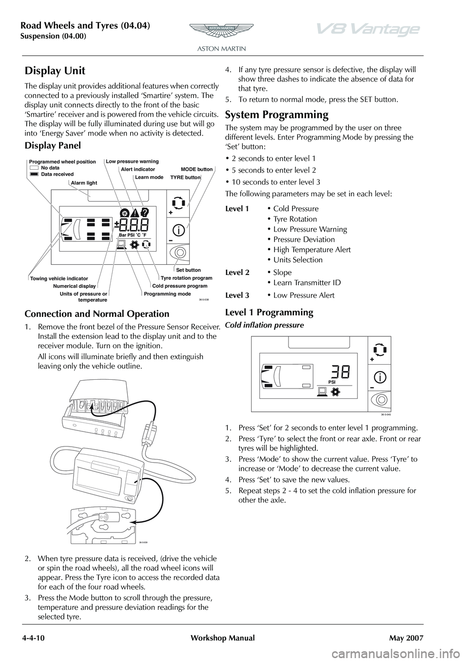
Display Panel
Connection and Normal Operation
1. Remove the front bezel of the Pressure Sensor Receiver. Install the extension lead to the display unit and to the
receiver module. Turn on the ignition.
All icons will illuminate briefly and then extinguish
leaving only the vehicle outline.
2. When tyre pressure data is received, (drive the vehicle
or spin the road wheels), all the road wheel icons will
appear. Press the Tyre icon to access the recorded data
for each of the four road wheels.
3. Press the Mode button to scroll through the pressure, temperature and pressure deviation readings for the
selected tyre. 4. If any tyre pressure sensor is defective, the display will
show three dashes to indicate the absence of data for
that tyre.
5. To return to normal mode, press the SET button.
System Programming
The system may be programmed by the user on three
different levels. Enter Progra mming Mode by pressing the
‘Set’ button:
• 2 seconds to enter level 1
• 5 seconds to enter level 2
• 10 seconds to enter level 3
The following parameters ma y be set in each level:
Level 1 Programming
Cold inflation pressure
1. Press ‘Set’ for 2 seconds to enter level 1 programming .
2. Press ‘Tyre’ to select the front or rear axle. Front or rear
tyres will be highlighted.
3. Press ‘Mode’ to show the current value. Press ‘Tyre’ to increase or ‘Mode’ to decrease the current value.
4. Press ‘Set’ to save the new values.
5. Repeat steps 2 - 4 to set the cold inflation pressure for other the axle.
Programmed wheel position No data
Data received
Alarm light Low pressure warning
Alert indicatorLearn mode MODE button
Set button
Tyre rotation program
Cold pressure program
Programming mode
Towing vehicle indicator
Numerical display
Units of pressure or temperature TYRE button
36-5-038
36-5-039
Level 1
• Cold Pressure
• Tyre Rotation
• Low Pressure Warning
• Pressure Deviation
• High Temperature Alert
•Units Selection
Level 2 •Slope
• Learn Transmitter ID
Level 3 • Low Pressure Alert
PSI
36-5-045
Page 461 of 947
Road Wheels and Tyres (04.04)
Suspension (04.00)
May 2007 Workshop Manual 4-4-11
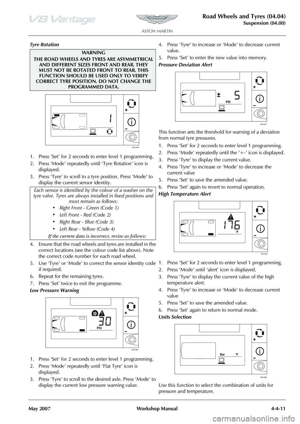
Tyre Rotation
1. Press ‘Set’ for 2 seconds to enter level 1 programming .
2. Press ‘Mode’ repeatedly until ‘Tyre Rotation’ icon is displayed.
3. Press ‘Tyre’ to scroll to a tyre position. Press ‘Mode’ to display the current sensor identity.
4. Ensure that the road wheels and tyres are installed in the correct locations (see the colour code list above). Note
the correct code number for each road wheel.
5. Use ‘Tyre’ or ‘Mode’ to co rrect the sensor identity code
if required.
6. Repeat for the remaining tyres.
7. Press ‘Set’ twice to exit the programme.
Low Pressure Warning
1. Press ‘Set’ for 2 seconds to enter level 1 programming .
2. Press ‘Mode’ repeatedly until ‘Flat Tyre’ icon is displayed.
3. Press ‘Tyre’ to scroll to th e desired axle. Press ‘Mode’ to
display the current low pressure warning value. 4. Press ‘Tyre’ to increase or
‘Mode’ to decrease current
value.
5. Press ‘Set’ to enter the new value into memory.
Pressure Deviation Alert
This function sets the threshold for warning of a deviation
from normal tyre pressures.
1. Press ‘Set’ for 2 seconds to enter level 1 programming .
2. Press ‘Mode’ repeatedly until the ‘+-’ icon is displayed.
3. Press ‘Tyre’ to display the current value.
4. Press ‘Tyre’ to increase or ‘Mode’ to decrease the
current value
5. Press ‘Set’ to save the amended value.
6. Press ‘Set’ again to revert to normal operation.
High Temperature Alert
1. Press ‘Set’ for 2 seconds to enter level 1 programming .
2. Press ‘Mode’ until ‘ale rt’ icon is displayed.
3. Press ‘Tyre’ to display the current value of the high temperature alert.
4. Press ‘Tyre’ to increase or ‘Mode’ to decrease current
value
5. Press ‘Set’ to save the amended value.
6. Press ‘Set’ again to return to normal mode.
Units Selection
Use this function to select the combination of units for
pressure and temperature.
WAR NI N G
THE ROAD WHEELS AND TYRES ARE ASYMMETRICAL AND DIFFERENT SIZES FRONT AND REAR. THEY
MUST NOT BE ROTATED FRONT TO REAR. THIS FUNCTION SHOULD BE USED ONLY TO VERIFY
CORRECT TYRE POSITION. DO NOT CHANGE THE PROGRAMMED DATA.
Each sensor is identified by th e colour of a washer on the
tyre valve. Tyres are always in stalled in fixed positions and
must remain as follows:
• Right Front - Green (Code 1)
• Left Front - Red (Code 2)
Page 462 of 947
Road Wheels and Tyres (04.04)
Suspension (04.00)4-4-12 Workshop Manual May 2007
1. Press ‘Set’ for 2 seconds to enter level 1 programming .
2. Press ‘Mode’ until pressure / temperature units are displayed.
3. Press ‘Tyre’ to enter ‘Units Selection’ mode.
4. Use ‘Tyre’ or ‘Mode’ to scroll through four combinations of pressure / temperature units.
5. Press ‘Set’ to save the selected combination of units.
6. Press the ‘Set’ button again to revert to normal mode.
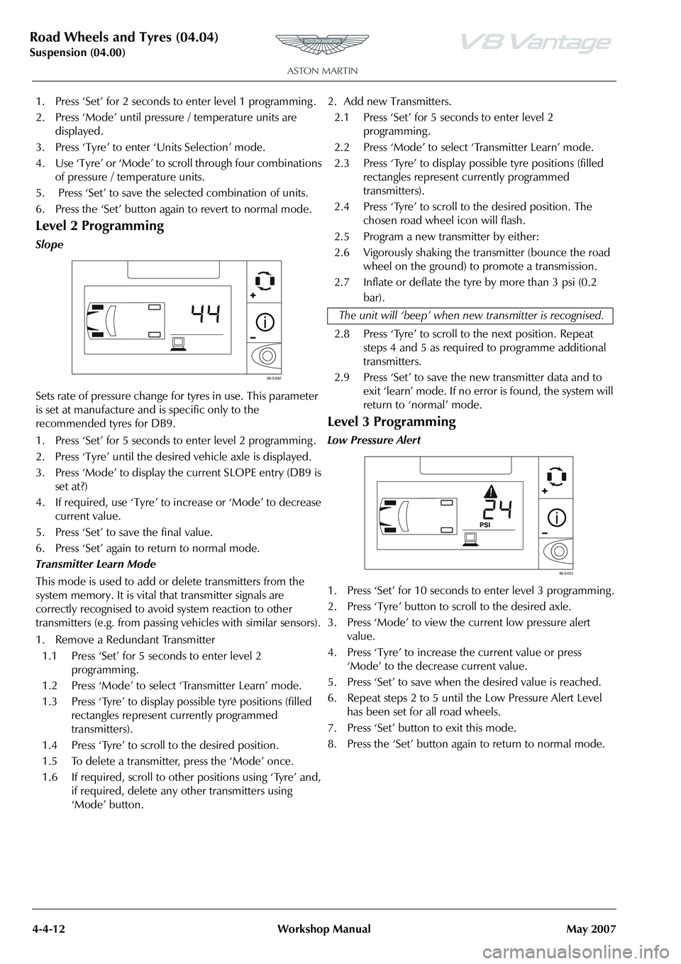
Level 2 Programming
Slope
Sets rate of pressure change for tyres in use. This parameter
is set at manufacture and is specific only to the
recommended tyres for DB9.
1. Press ‘Set’ for 5 seconds to enter level 2 programming .
2. Press ‘Tyre’ until the desired vehicle axle is displayed.
3. Press ‘Mode’ to display the current SLOPE entry (DB9 is set at?)
4. If required, use ‘Tyre’ to increase or ‘Mode’ to decrease current value.
5. Press ‘Set’ to save the final value.
6. Press ‘Set’ again to return to normal mode.
Transmitter Learn Mode
This mode is used to add or delete transmitters from the
system memory. It is vital that transmitter signals are
correctly recognised to avoid system reaction to other
transmitters (e.g. from passing vehicles with similar sensors).
1. Remove a Redundant Transmitter 1.1 Press ‘Set’ for 5 seconds to enter level 2 programming .
1.2 Press ‘Mode’ to select ‘Transmitter Learn’ mode.
1.3 Press ‘Tyre’ to display possible tyre positions (filled rectangles represent currently programmed
transmitters).
1.4 Press ‘Tyre’ to scroll to the desired position.
1.5 To delete a transmitter, press the ‘Mode’ once.
1.6 If required, scroll to other positions using ‘Tyre’ and, if required, delete any other transmitters using
‘Mode’ button. 2. Add new Transmitters.
2.1 Press ‘Set’ for 5 seconds to enter level 2 programming .
2.2 Press ‘Mode’ to select ‘Transmitter Learn’ mode.
2.3 Press ‘Tyre’ to display possible tyre positions (filled rectangles represent currently programmed
transmitters).
2.4 Press ‘Tyre’ to scroll to the desired position. The chosen road wheel icon will flash.
2.5 Program a new transmitter by either:
2.6 Vigorously shaking the transmitter (bounce the road wheel on the ground) to promote a transmission.
2.7 Inflate or deflate the tyre by more than 3 psi (0.2 bar).
2.8 Press ‘Tyre’ to scroll to the next position. Repeat steps 4 and 5 as required to programme additional
transmitters.
2.9 Press ‘Set’ to save the new transmitter data and to exit ‘learn’ mode. If no error is found, the system will
return to ‘normal’ mode.
Level 3 Programming
Low Pressure Alert
1. Press ‘Set’ for 10 seconds to enter level 3 programming .
2. Press ‘Tyre’ button to scroll to the desired axle.
3. Press ‘Mode’ to view the current low pressure alert value.
4. Press ‘Tyre’ to increase the current value or press ‘Mode’ to the decrease current value.
5. Press ‘Set’ to save when the desired value is reached.
6. Repeat steps 2 to 5 until the Low Pressure Alert Level has been set for all road wheels.
7. Press ‘Set’ button to exit this mode.
8. Press the ‘Set’ button again to return to normal mode.
36-5-052
The unit will ‘beep’ when ne w transmitter is recognised.
36-5-051
Page 507 of 947
Anti-lock Braking System (ABS) (06.09)
Brake system (06.00)
Issue 4, November 2008 Workshop Manual 6-9-1
Brake system (06.00)
Anti-lock Braking System (ABS) (06.09)
The anti-lock braking system (ABS) is a four-channel system
having independent inputs from all four-wheel speed
sensors.
The ABS module, monitors signals from the sensors to
calculate, brake slip and the acceleration / deceleration of
individual wheels. When the brake pedal is depressed, and
the ABS module detects incipient wheel lock-up from the
incoming signals, it triggers the re-circulation pump inside
the module’s hydraulic modulator, and the solenoid valves
for the wheel(s) concerned. Brake pressure, is then
modulated to increase / decrease or remain constant at the
wheel(s) concerned until whee l lock-up is eliminated. The
ABS provides self-diagnosis and any malfunction within the
system will be indicated to the dr iver by the illumination of
the brake warning light and ‘ABS FAULT’ displayed in the
message centre right. Should a fault develop within the ABS,
the brake system will operate conventionally and with the
same standard of performanc e as a vehicle not equipped
with ABS.
Dynamic Stability Control
Dynamic Stability Control (DSC ) is a closed-loop system
designed to enhance driving safety by improving vehicle
handling when the tyres are at the limits of their grip
capabilities. This is achieved through instantaneous,
electronically controlled, reduction of engine torque and
strategic application of the brakes at individual wheels.
By using the principle that by controlling the brakes
individually it is possible, to an extent, to steer the vehicle.
This principle can be used to enhance driving safety by
correcting the vehicle’s yaw moment (turning force), when
the vehicle fails to follow th e driver’s steering inputs.
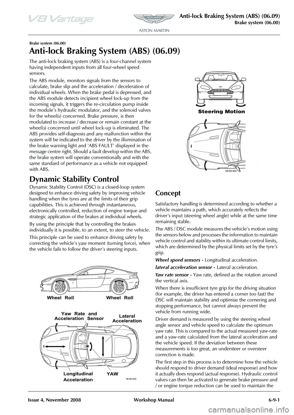
Concept
Satisfactory handling is determined according to whether a
vehicle maintains a path, wh ich accurately reflects the
driver
Page 602 of 947
Steering Gear (11.01)
Steering (11.00)
Issue 5, January 2010 Workshop Manual 11-1-3
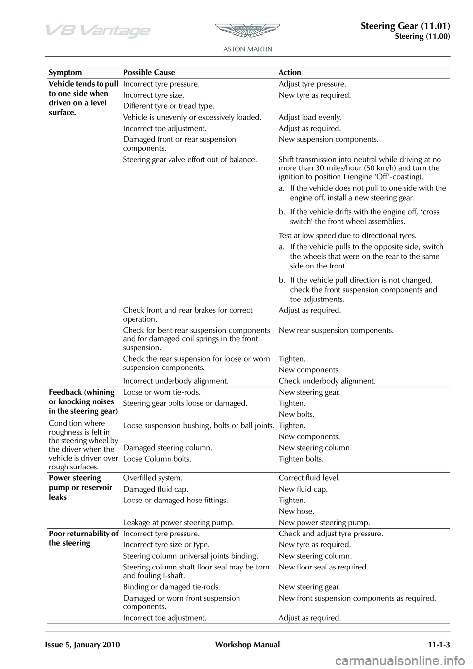
Vehicle tends to pull
to one side when
driven on a level
surface. Incorrect tyre pressure. Adjust tyre pressure.
Incorrect tyre size.
Different tyre or tread type.
New tyre as required.
Vehicle is unevenly or excessively loaded. Adjust load evenly.
Incorrect toe adjustment. Adjust as required.
Damaged front or rear suspension
components. New suspension components.
Steering gear valve effort out of balance. Shift transmission into neutral while driving at no more than 30 miles/hour (50 km/h) and turn the
ignition to position I (engine ‘Off’-coasting).
a. If the vehicle does not pull to one side with the
engine off, install a new steering gear.
b. If the vehicle drifts with the engine off, ‘cross switch’ the front wheel assemblies.
Test at low speed due to directional tyres.
a. If the vehicle pulls to the opposite side, switch the wheels that were on the rear to the same
side on the front.
b. If the vehicle pull direction is not changed, check the front suspension components and
toe adjustments.
Check front and rear brakes for correct
operation. Adjust as required.
Check for bent rear suspension components
and for damaged coil springs in the front
suspension. New rear suspension components.
Check the rear suspension for loose or worn
suspension components. Tighten.
New components.
Incorrect underbody alignment. Check underbody alignment.
Feedback (whining
or knocking noises
in the steering gear)
Condition where
roughness is felt in
the steering wheel by
the driver when the
vehicle is driven over
rough surfaces. Loose or worn tie-rods. New steering gear.
Steering gear bolts loose or damaged. Tighten.
New bolts.
Loose suspension bushing , bolts or ball joints. Tighten.
New components.
Damaged steering column.
Loose Column bolts. New steering column.
Tighten bolts.
Power steering
pump or reservoir
leaks Overfilled system. Correct fluid level.
Damaged fluid cap. New fluid cap.
Loose or damaged hose fittings. Tighten.
New hose.
Leakage at power steering pump. New power steering pump.
Poor returnability of
the steering Incorrect tyre pressure. Check
and adjust tyre pressure.
Incorrect tyre size or ty pe. New tyre as required.
Steering column universal joints binding . New steering column.
Steering column shaft floor seal may be torn
and fouling I-shaft. New floor seal as required.
Binding or damaged tie-rods. New steering gear.
Damaged or worn front suspension
components. New front suspension components as required.
Incorrect toe adjustment. Adjust as required.
SymptomPossible CauseAction
Page 605 of 947
Power Steering (11.02)
Steering (11.00)11-2-2 Workshop Manual Issue 5, January 2010
Maintenance
Power Steering System - Bleed
Procedure
1. Do a check of the fluid level in the PAS fluid reservoir. Add fluid if necessary.
2. Start the engine and let it idle for 20 seconds.
3. Operate the steering fully to the left and then the right through three cycles.
4. Stop the engine.
5. Wait for five minutes then do a check of the fluid level in the PAS fluid reservoir again.
6. Add fluid if necessary.
7. Install the PAS fluid reservoir cap.
Power Steering Pump-Renew
Removal
1. Remove A/C compressor (see Workshop Manual procedure 03.05.BE Compre ssor - Air Conditioning -
Renew).
2. Coolant drain (see Workshop Manual procedure 03.03.AD Coolant - Drain & Refill).
3. Remove PAS fluid from reservoir.
4. Disconnect HP union from PAS pump pipe.
5. Remove bolt P-clip suction hose to body.
6. Remove bolt (x1) HP pump pipe to engine.
7. Remove bolts (x3) PAS pump to engine.
8. Disconnect bottom hose and move aside.
9. Unclip (x1) harness from cylinder head for access.
10. Manouvre pump forward and up.
11. Disconnect suction hose (cut off clip) and remove pump.
12. Remove HP union pipe from pump (mark position on
pump).
Installation
1. Install HP union pipe to pump (align correctly), fit new O-ring.
2. Install pump to vehicle connect suction pipe to PAS pump, align timing marks and fit new clip.
3. Manouvre pump into position.
4. Install bolts (x3) PAS pump to engine (torque).
5. Install bolt (x1) HP pump pipe to engine (torque).
6. Connect bottom hose.
7. Clip (x1) harness from cylinder head for access. 8. Install bolt P-clip suction hose to body (torque).
9. Connect HP union to PAS pump pipe, replace O-ring
(torque).
10. Coolant refill (see Workshop Manual procedure 03.03.AD Coolant - Drain & Refill).
11. Install A/C compressor (see Workshop Manual procedure 03.05.BE Compre ssor - Air Conditioning -
Renew).
12. Top-up PAS fluid.
13. Start and run engine, operate steering lock to lock x2.
14. Top-up PAS fluid.
Power Assisted Steering (PAS) Rack -
Remove and Install
Removal
1. Disconnect the battery ground cable.
2. Remove the front undertray (refer to Workshop Manual Procedure 01.02.NB - Front Undertray).
3. Remove the front wheels and tyres (refer to Workshop Manual Procedure 04.04.ED - Wheel and Tyre - Pair).
4. Remove the front right side wheel-arch liner (refer to Workshop Manual Procedure 01.02.GB - Front Right
Side Wheel-Arch Liner).
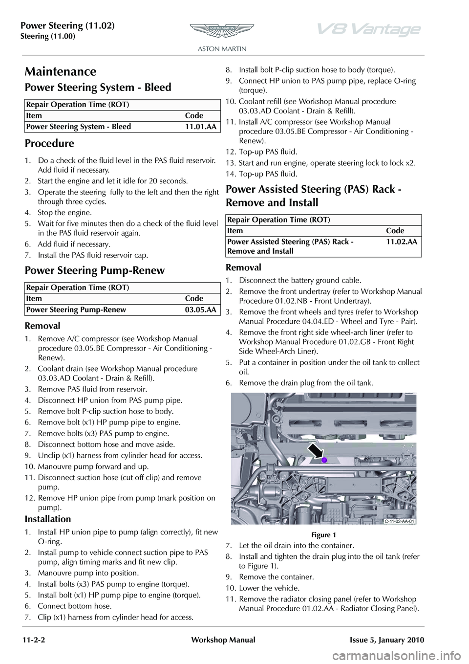
5. Put a container in position under the oil tank to collect oil.
6. Remove the drain plug from the oil tank.
Figure 1
7. Let the oil drain into the container.
8. Install and tighten the drain plug into the oil tank (refer to Figure 1).
9. Remove the container.
10. Lower the vehicle.
11. Remove the radiator closing panel (refer to Workshop Manual Procedure 01.02.AA - Radiator Closing Panel).
Repair Operation Time (ROT)
Repair Operation Time (ROT)
Repair Operation Time (ROT)
ItemCode
Power Assisted Steering (PAS) Rack -
Remove and Install 11.02.AA
Page 614 of 947
Power Steering (11.02)
Steering (11.00)
Issue 5, January 2010 Workshop Manual 11-2-11
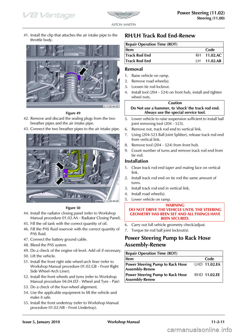
41. Install the clip that attaches the air intake pipe to the throttle body.
Figure 49
42. Remove and discard the sealing plugs from the two breather pipes and the air intake pipe.
43. Connect the two breather pipes to the air intake pipe.
Figure 50
44. Install the radiator closing panel (refer to Workshop Manual procedure 01.02.AA - Radiator Closing Panel).
45. Fill the oil tank with the correct quantity of oil.
46. Fill the PAS fluid reservoir with the correct quantity of
PAS fluid.
47. Connect the battery ground cable.
48. Bleed the PAS system.
49. Do a check of the engine oi l level. Add oil if necessary.
50. Lift the vehicle.
51. Install the front right side wheel-arch liner (refer to Workshop Manual procedure 01.02.GB - Front Right
Side Wheel-Arch Liner).
52. Install the front wheels and tyres (refer to Workshop Manual procedure 04.04.ED - Wheel and Tyre - Pair)
53. Do a check of the four-wheel alignment.
54. Use the applicable equipment to lift the vehicle and make it safe.
55. Install the front undertray (refer to Workshop Manual procedure 01.02.NB - Front Undertray).
RH/LH Track Rod End-Renew
Removal
1. Raise vehicle on ramp.
2. Remove road wheel(s).
3. Loosen tie rod locknut.
4. Install tool (204 - 524) on front hub, install and tighten
wheel nuts.
5. Lower vehicle to raise suspension sufficient to install ball joint removing tool (204 - 523).
6. Remove nut, track rod end to vertical link.
7. Using (204-523 Ball Joint Sp litter), release track rod end
from vertical link.
8. Remove tool (204 - 524) from front hub.
9. Count number of turns and remove track rod end from tie rod.
Installation
1. Clean track rod end taper and mating face on vertical link.
2. Install track rod end on tie rod the same amount of turns.
3. Install track rod end in vertical link.
4. Install road wheel(s).
5. Lower vehicle on ramp.
6. Carry out full vehicle geometry check/adjust.
7. Torque tie rod ball joint locknut(s).
Power Steering Pump to Rack Hose
Assembly-Renew
Repair Operation Time (ROT)
Repair Operation Time (ROT)