heater ASTON MARTIN V8 VANTAGE 2010 Workshop Manual
[x] Cancel search | Manufacturer: ASTON MARTIN, Model Year: 2010, Model line: V8 VANTAGE, Model: ASTON MARTIN V8 VANTAGE 2010Pages: 947, PDF Size: 43.21 MB
Page 3 of 947
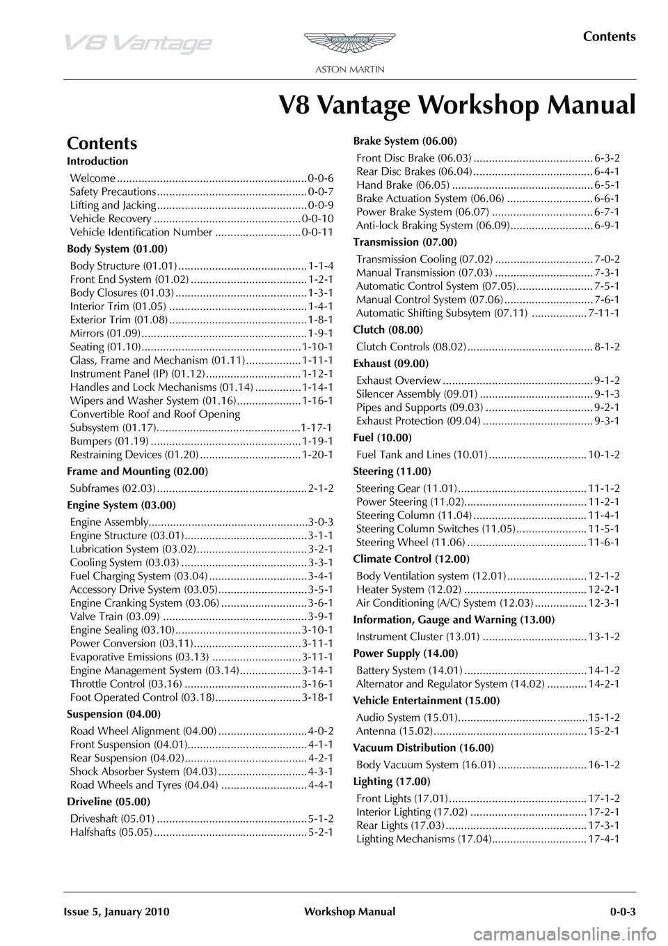
Contents
Issue 5, January 2010 Workshop Manual 0-0-3
V8 Vantage Workshop Manual
Contents
IntroductionWelcome .............................................................. 0-0-6
Safety Precautions ................................................. 0-0-7
Lifting and Jacking ................................................. 0-0-9
Vehicle Recovery ................................................ 0-0-10
Vehicle Identification Number ............................ 0-0-11
Body System (01.00) Body Structure (01.01) .......................................... 1-1-4
Front End System (01.02) ...................................... 1-2-1
Body Closures (01.03) ........................................... 1-3-1
Interior Trim (01.05) ............................................. 1-4-1
Exterior Trim (01.08) ............................................. 1-8-1
Mirrors (01.09) ...................................................... 1-9-1
Seating (01.10).................................................... 1-10-1
Glass, Frame and Mechanism (01.11) .................. 1-11-1
Instrument Panel (IP) (01.12) . .............................. 1-12-1
Handles and Lock Mechanisms (01.14) ............... 1-14-1
Wipers and Washer System (01.16)..................... 1-16-1
Convertible Roof and Roof Opening
Subsystem (01.17)................ ...............................1-17-1
Bumpers (01.19) ................................................. 1-19-1
Restraining Devices (01.20) .... ............................. 1-20-1
Frame and Mounting (02.00) Subframes (02.03) ................................................. 2-1-2
Engine System (03.00) Engine Assembly....................................................3-0-3
Engine Structure (03.01)........................................ 3-1-1
Lubrication System (03.02).................................... 3-2-1
Cooling System (03.03) ......................................... 3-3-1
Fuel Charging System (03.04) ................................ 3-4-1
Accessory Drive System (03.05)............................. 3-5-1
Engine Cranking System (03. 06) ............................ 3-6-1
Valve Train (03.09) ............................................... 3-9-1
Engine Sealing (03.10)......................................... 3-10-1
Power Conversion (03.11)................................... 3-11-1
Evaporative Emissions (03.13) ............................. 3-11-1
Engine Management System (0 3.14).................... 3-14-1
Throttle Control (03.16) ...... ................................ 3-16-1
Foot Operated Control (03.18)............................ 3-18-1
Suspension (04.00) Road Wheel Alignment (04.00) ............................. 4-0-2
Front Suspension (04.01)....................................... 4-1-1
Rear Suspension (04.02)........................................ 4-2-1
Shock Absorber System (04.03) ............................. 4-3-1
Road Wheels and Tyres (04.04) ............................ 4-4-1
Driveline (05.00) Driveshaft (05.01) ................................................. 5-1-2
Halfshafts (05.05) .................................................. 5-2-1 Brake System (06.00)
Front Disc Brake (06.03) ....................................... 6-3-2
Rear Disc Brakes (06.04) ....................................... 6-4-1
Hand Brake (06.05) .............................................. 6-5-1
Brake Actuation System (06.06 ) ............................ 6-6-1
Power Brake System (06.07) ................................. 6-7-1
Anti-lock Braking System (06.09)........................... 6-9-1
Transmission (07.00) Transmission Cooling (07.02) ................................ 7-0-2
Manual Transmission (07.03) ................................ 7-3-1
Automatic Control System (07.05)......................... 7-5-1
Manual Control System (07.06) ............................. 7-6-1
Automatic Shifting Subsytem (07.11) .................. 7-11-1
Clutch (08.00) Clutch Controls (08.02) ......................................... 8-1-2
Exhaust (09.00) Exhaust Overview ................................................. 9-1-2
Silencer Assembly (09.01) ..................................... 9-1-3
Pipes and Supports (09.03) ................................... 9-2-1
Exhaust Protection (09.04) .................................... 9-3-1
Fuel (10.00) Fuel Tank and Lines (10.01) ................................ 10-1-2
Steering (11.00) Steering Gear (11.01) .......................................... 11-1-2
Power Steering (11.02)........................................ 11-2-1
Steering Column (11.04) ..................................... 11-4-1
Steering Column Switches (1 1.05) ....................... 11-5-1
Steering Wheel (11.06) ....................................... 11-6-1
Climate Control (12.00) Body Ventilation system (12.01) .......................... 12-1-2
Heater System (12.02) ........................................ 12-2-1
Air Conditioning (A/C) System (12.03) ................. 12-3-1
Information, Gauge and Warning (13.00) Instrument Cluster (13.01) .................................. 13-1-2
Power Supply (14.00) Battery System (14.01) ........................................ 14-1-2
Alternator and Regulator System (14.02) ............. 14-2-1
Vehicle Entertainment (15.00) Audio System (15.01)................................ ..........15-1-2
Antenna (15.02).................................................. 15-2-1
Vacuum Distribution (16.00) Body Vacuum System (16.01) ............................. 16-1-2
Lighting (17.00) Front Lights (17.01) ............................................. 17-1-2
Interior Lighting (17.02) ...................................... 17-2-1
Rear Lights (17.03) .............................................. 17-3-1
Lighting Mechanisms (17.04). .............................. 17-4-1
Page 8 of 947
Safety Precautions
0-0-8 Workshop Manual Issue 5, January 2010
Tools and Equipment
• Do not leave tools, equipment, spilt oil, etc. around or on the work area.
• Ensure that tools and equipment used are in good condition; do not use damaged or defective tools or
equipment.
• Do not apply heat in an attempt to free stiff nuts or fittings; as well as causing damage to protective coatings, the stray
heat may damage electronic equipment, harnesses and
brake lines.
• Use the recommended service tool where instructed to do so.
Used Engine Oil
Prolonged and repeated contact with mineral oil will result
in the removal of natural fats from the skin, leading to
dryness, irritation and dermatitis. In addition, used engine
oil contains potentially harmful contaminants which may
cause skin cancer. Adequate means of skin protection and
washing facilities should be provided.
Health protection precautions
• Avoid prolonged and repeated contact with oils, particularly used engine oil.
• Wear protective clothing , including impervious gloves where practicable.
• Do not put oily rags in pockets.
• Avoid contaminating clothes with oil.
• Overalls must be cleaned regularly. Discard un-washable clothes and oil impregnated footwear.
• First aid treatment should be obtained immediately for open cuts or wounds.
• Use barrier creams, apply before each work period to help the removal of oil from the skin.
• Wash with soap and water to ensure all oil is removed. Preparations containing lanolin replace the natural skin
oils which have been removed.
• Do not use petrol, kerosene, diesel fuel, gas oil, thinners or solvents for washing skin.
• If skin disorders develop, obtain medical advice.
• Where practicable, degrease components prior to handling .
• Where there is a risk of eye contact, eye protection should
be worn. In addition, an ey e wash facility should be
provided.
Environmental Protection
It is illegal to pour used oil on the ground, down sewers or
drains, or into water courses. The burning of used engine oil
in small space heaters or boilers is not recommended unless
emission control equipment is in stalled; in case of doubt,
contact the Local Authority for ad vice on disposal facilities.
Page 13 of 947
Issue 5, January 2010 Workshop Manual 1-1-1
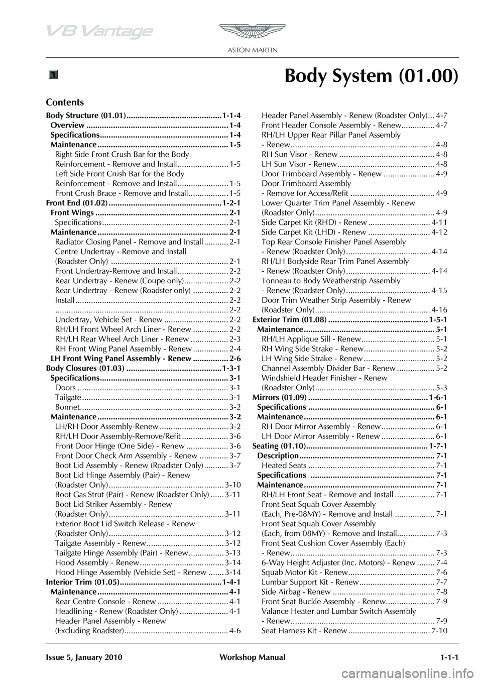
Body System (01.00)
Contents
Body Structure (01.01)........................................... 1-1-4Overview ................................................................ 1-4
Specifications.......................................................... 1-4
Maintenance ........................................................... 1-5Right Side Front Crush Bar for the Body
Reinforcement - Remove and Install ....................... 1-5
Left Side Front Crush Bar for the Body
Reinforcement - Remove and Install ....................... 1-5
Front Crush Brace - Remove and Install .................. 1-5
Front End (01.02) ................................................... 1-2-1 Front Wings ............................................................ 2-1Specifications ......................................................... 2-1
Maintenance ........................................................... 2-1 Radiator Closing Panel - Remove and Install ........... 2-1
Centre Undertray - Remove and Install
(Roadster Only) ..................................................... 2-1
Front Undertray-Remove and Install ....................... 2-2
Rear Undertray - Renew (Coupe only).................... 2-2
Rear Undertray - Renew (Roadster only) ................ 2-2
Install ..................................................................... 2-2.............................................................................. 2-2
Undertray, Vehicle Set - Renew ............................. 2-2
RH/LH Front Wheel Arch Liner - Renew ................ 2-2
RH/LH Rear Wheel Arch Liner - Renew ................. 2-3
RH Front Wing Panel Assembly - Renew ................ 2-4
LH Front Wing Panel Assembly - Renew ................ 2-6
Body Closures (01.03) ........................................... 1-3-1 Specifications.......................................................... 3-1Doors .................................................................... 3-1
Tailgate .................................................................. 3-1
Bonnet................................................................... 3-2
Maintenance ........................................................... 3-2 LH/RH Door Assembly-Renew ............................... 3-2
RH/LH Door Assembly-Remove/Refit ..................... 3-6
Front Door Hinge (One Side) - Renew ................... 3-6
Front Door Check Arm Assembly - Renew ............. 3-7
Boot Lid Assembly - Renew (Roadster Only) ........... 3-7
Boot Lid Hinge Assembly (Pair) - Renew
(Roadster Only) .................................................... 3-10
Boot Gas Strut (Pair) - Renew (Roadster Only) ...... 3-11
Boot Lid Striker Assembly - Renew
(Roadster Only) .................................................... 3-11
Exterior Boot Lid Switch Release - Renew
(Roadster Only) .................................................... 3-12
Tailgate Assembly - Renew ................................... 3-12
Tailgate Hinge Assembly (Pair) - Renew ................ 3-13
Hood Assembly - Renew ...................................... 3-14
Hood Hinge Assembly (Vehicle Set) - Renew ....... 3-14
Interior Trim (01.05).............................................. 1-4-1 Maintenance ........................................................... 4-1Rear Centre Console - Renew ................................ 4-1
Headlining - Renew (Roadster Only) ...................... 4-1
Header Panel As sembly - Renew
(Excluding Roadster)............................................... 4-6 Header Panel Assembly - Renew (Roadster Only)... 4-7
Front Header Console Assembly - Renew............... 4-7
RH/LH Upper Rear Pillar Panel Assembly
- Renew ................................................................. 4-8
RH Sun Visor - Renew ........................................... 4-8
LH Sun Visor - Renew ............................................ 4-8
Door Trimboard Assembly - Renew ....................... 4-9
Door Trimboard Assembly
- Remove for Access/Refit ...................................... 4-9
Lower Quarter Trim Panel Assembly - Renew
(Roadster Only)...................................................... 4-9
Side Carpet Kit (RHD) - Renew ............................ 4-11
Side Carpet Kit (LHD) - Renew ............................ 4-12
Top Rear Console Fini
sher Panel Assembly
- Renew (Roadster Only) ...................................... 4-14
RH/LH Bodyside Rear Trim Panel Assembly
- Renew (Roadster Only) ...................................... 4-14
Tonneau to Body Weatherstrip Assembly
- Renew (Roadster Only) ...................................... 4-15
Door Trim Weather Strip Assembly - Renew
(Roadster Only).................................................... 4-16
Exterior Trim (01.08) ............................................. 1-5-1 Maintenance ........................................................... 5-1RH/LH Applique Sill - Renew ................................. 5-1
RH Wing Side Strake - Renew................................ 5-2
LH Wing Side Strake - Renew ................................ 5-2
Channel Assembly Divider Bar - Renew ................. 5-2
Windshield Header Finisher - Renew
(Roadster Only)...................................................... 5-3
Mirrors (01.09) ...................................................... 1-6-1 Specifications ......................................................... 6-1
Maintenance ........................................................... 6-1RH Door Mirror Assembly - Renew ........................ 6-1
LH Door Mirror Assembly - Renew ........................ 6-1
Seating (01.10)....................................................... 1-7-1 Description ............................................................. 7-1Heated Seats ......................................................... 7-1
Specifications ........................................................ 7-1
Maintenance ........................................................... 7-1 RH/LH Front Seat - Remove and Install .................. 7-1
Front Seat Squab Cover Assembly
(Each, Pre-08MY) - Remove and Install .................. 7-1
Front Seat Squab Cover Assembly
(Each, from 08MY) - Remove and Install................. 7-3
Front Seat Cushion Cover Assembly (Each)
- Renew ................................................................. 7-3
6-Way Height Adjuster (Inc. Motors) - Renew ........ 7-4
Squab Motor Kit - Renew....................................... 7-6
Lumbar Support Kit - Renew .................................. 7-7
Side Airbag - Renew .............................................. 7-8
Front Seat Buckle Assembly - Renew...................... 7-9
Valance Heater and Lumbar Switch Assembly
- Renew ................................................................. 7-9
Seat Harness Kit - Renew ..................................... 7-10
Page 29 of 947

Body Closures (01.03)
Body System (01.00)
May 2007 Workshop Manual 1-3-3
10. Disconnect door speaker multiplug (see Figure 2).
11. Remove bolts (x3), remove door speaker assembly.
12. Remove bolts (x4) securing door control module to door
panel (see Figure 3).
13. Disconnect multiplugs (x3), remove door control module. 14. Remove bolts (x3) securing side impact sensor mounting
plate, disconnect multiplug, remove plate assembly (see
Figure 4).
15. Pull fixed glass upwards and away from cheater panel, releasing rubber surround at top. Remove fixed glass.
16. Mark door glass around rear glass clamp.
17. Remove glass clamp bolts (x2), raise and remove door glass from door frame.
18. Disconnect multiplug from door glass regulator motor
(see Figure 5).
Figure 2
Figure 3
A010808
A191003
Figure 4
Figure 5
A012004
A011139
Page 30 of 947

Body Closures (01.03)
Body System (01.00)1-3-4 Workshop Manual May 2007
19. Remove nuts (x4) and Torx screws (x3) securing door glass regulator to door frame (see Figure 6).
20. Carefully remove regulator mechanism through the larger door frame aperture.
21. Remove door mirror rubber cheater (see Figure 7).
22. Disconnect door mirror mult iplug, release harness fir
tree clips (x2) and self adhe sive clip (see Figure 8). 23. Remove Torx Bolts (x3) and screw from door glass
channel. Remove door mirror assembly.
24. Remove aperture seal from inner door frame.
25. Remove fir tree trim pins (x3), release/remove rear
weatherstrip from door frame/glass channel.
26. Disconnect door latch multiplug.
27. Release inner and outer cable from external door handle (see Figure 9).
28. Remove nuts (x3) securi ng external door handle,
remove door handle (see Figure 10).
29. Loosen upper nut, remove lower nut securing keylock mechanism to door frame.
Figure 6
Figure 7
Figure 8
A011139A
A0108144
A0108143
Figure 9
Figure 10
A0114138A
A0114138
Page 32 of 947
Body Closures (01.03)
Body System (01.00)1-3-6 Workshop Manual May 2007
19. Install inner and outer cable to external door handle.
20. Connect multiplug to door latch.
21. Install rear weatherstrip to glass channel and door frame. Install fir tree trim pins (x3)
22. Install seal to inner door aperture.
23. Position door mirror, install and torque tighten Torx bolts (x3) and screw (glass channel).
24. Connect door mirror multip lug, secure harness with fir
tree clips (x2) and adhesive clip.
25. Install rubber cheater to door frame, secure with fir tree trim pins (x3).
26. Install glass regulator as sembly into door frame.
27. Install and torque tighten nuts (x4) and Torx screws (x3) securing regulator assembly to door frame.
28. Connect multiplug to glass regulator.
29. Install door glass, install clamp bolts (x2), align marks on glass to rear clamp. Do not torque tighten at this stage.
30. Install fixed glass, ensure rubber surround is correctly installed.
31. Connect multiplug to side impact sensor, position
mounting plate, install and torque bolts (x3).
32. Position door control modu le, connect multiplugs (x3).
Install and torque tighten bolts (x4).
33. Position door speaker, install and torque tighten screws (x3). Connect multiplug to speaker.
34. Position door trimboard, connect multiplugs (x2).
35. Install trimboard to door frame, secure in clips.
36. Install and tighten screws (x5).
37. Install LH door assembly (see Workshop Manual procedure 01.03.FA Door Assembly - LH - Remove for
Access and Refit).
38. Battery isolation switch ‘ON’.
39. Glass front door - LH - Adjust and reset (see Workshop Manual procedure 01.11.BD Glass - Front Door - LH -
Adjust and Reset).
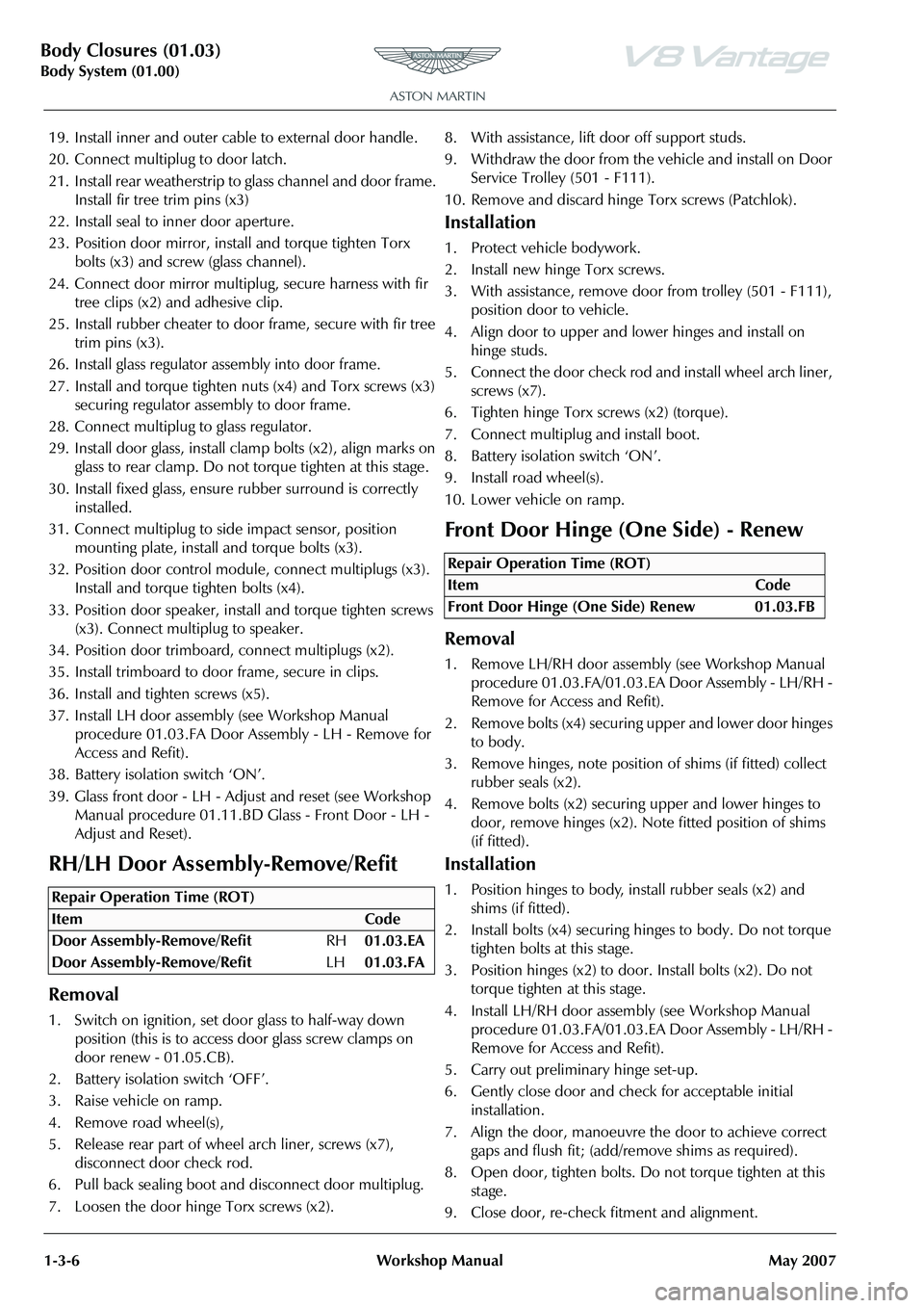
RH/LH Door Assembly-Remove/Refit
Removal
1. Switch on ignition, set door glass to half-way down position (this is to access door glass screw clamps on
door renew - 01.05.CB).
2. Battery isolation switch ‘OFF’.
3. Raise vehicle on ramp.
4. Remove road wheel(s),
5. Release rear part of whee l arch liner, screws (x7),
disconnect door check rod.
6. Pull back sealing boot and disconnect door multiplug.
7. Loosen the door hinge Torx screws (x2). 8. With assistance, lift door off support studs.
9. Withdraw the door from the vehicle and install on Door
Service Trolley (501 - F111).
10. Remove and discard hinge Torx screws (Patchlok).
Installation
1. Protect vehicle bodywork.
2. Install new hinge Torx screws.
3. With assistance, remove door from trolley (501 - F111),
position door to vehicle.
4. Align door to upper and lower hinges and install on hinge studs.
5. Connect the door check rod and install wheel arch liner, screws (x7).
6. Tighten hinge Torx screws (x2) (torque).
7. Connect multiplug and install boot.
8. Battery isolation switch ‘ON’.
9. Install road wheel(s).
10. Lower vehicle on ramp.
Front Door Hinge (One Side) - Renew
Removal
1. Remove LH/RH door assemb ly (see Workshop Manual
procedure 01.03.FA/01.03.EA Door Assembly - LH/RH -
Remove for Access and Refit).
2. Remove bolts (x4) securing upper and lower door hinges to body.
3. Remove hinges, note position of shims (if fitted) collect
rubber seals (x2).
4. Remove bolts (x2) securing upper and lower hinges to door, remove hinges (x2). No te fitted position of shims
(if fitted).
Installation
1. Position hinges to body, install rubber seals (x2) and shims (if fitted).
2. Install bolts (x4) securing hi nges to body. Do not torque
tighten bolts at this stage.
3. Position hinges (x2) to door. Install bolts (x2). Do not torque tighten at this stage.
4. Install LH/RH door assemb ly (see Workshop Manual
procedure 01.03.FA/01.03.EA Door Assembly - LH/RH -
Remove for Access and Refit).
5. Carry out preliminary hinge set-up.
6. Gently close door and check for acceptable initial installation.
7. Align the door, manoeuvre the door to achieve correct gaps and flush fit; (add/remove shims as required).
8. Open door, tighten bolts. Do not torque tighten at this stage.
9. Close door, re-check fitment and alignment.Repair Operation Time (ROT)
Repair Operation Time (ROT)
ItemCode
Front Door Hinge (One Side) Renew 01.03.FB
Page 66 of 947
Mirrors (01.09)
Body System (01.00)1-6-2 Workshop Manual May 2007
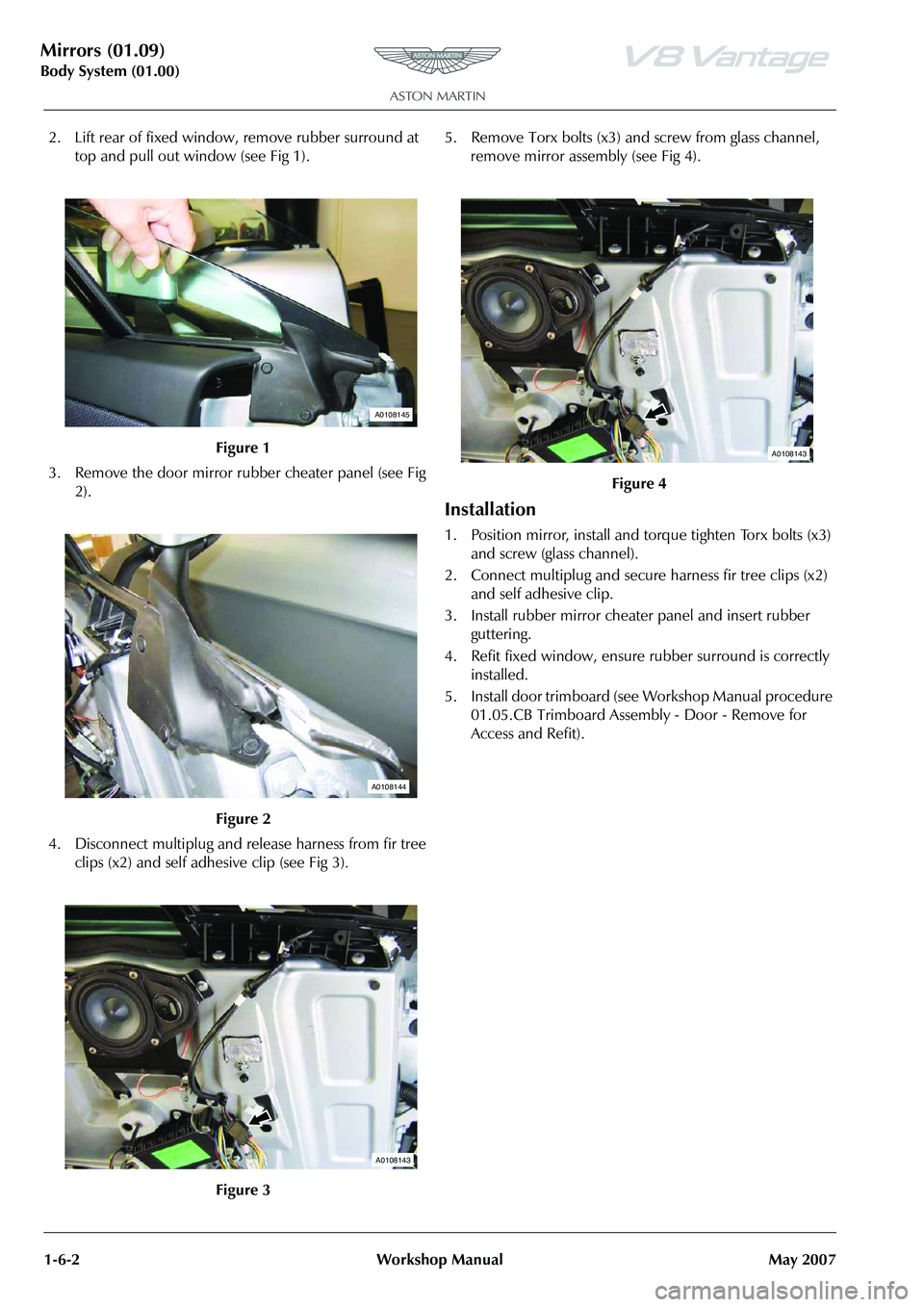
2. Lift rear of fixed window, remove rubber surround at
top and pull out window (see Fig 1).
3. Remove the door mirror rubber cheater panel (see Fig 2).
4. Disconnect multiplug and release harness from fir tree clips (x2) and self adhesive clip (see Fig 3). 5. Remove Torx bolts (x3) and screw from glass channel,
remove mirror assembly (see Fig 4).
Installation
1. Position mirror, install and to rque tighten Torx bolts (x3)
and screw (glass channel).
2. Connect multiplug and secure harness fir tree clips (x2) and self adhesive clip.
3. Install rubber mirror cheater panel and insert rubber guttering.
4. Refit fixed window, ensure rubber surround is correctly installed.
5. Install door trimboard (see Workshop Manual procedure 01.05.CB Trimboard Assembly - Door - Remove for
Access and Refit).
Figure 1
Figure 2
Figure 3
A0108145
A0108144
A0108143
Figure 4
A0108143
Page 67 of 947

Seating (01.10)
Body System (01.00)
Issue 4, November 2008 Workshop Manual 1-7-1
Body System (01.00)
Seating (01.10)
Description
The front seats are installed with the following features:
• Integral side airbags
•Head restraints
• Safety belt reel pretensioner
• Electrically adjustable seat positioning and lumbar support
• Heated seat (optional)
Heated Seats
The heated seat system comprises:
• Heated seat switches
• Backrest heater element
• Cushion heater element and thermostat
The heated seat function permits the electrical heating of the
seat back and cushion on the driver and front passenger
seats. The heating system of each seat is selected by separate
switches located on the inside of each seat base.
Once the heated seat function has been activated, it will
operate until one of the following conditions have been
satisfied:
• A fixed period of time has expired (10 minutes)
• If the engine is not running and the ignition key is removed
• A malfunction is detected by the heated seat module
Confirmation that the heated seat function is active is
indicated by the illumination of an amber light on the
switch.
Specifications Maintenance
RH/LH Front Seat - Remove and Install
Remove
1. Power seat fully forward.
2. Remove bolts (x2), securing rear of seat to seat rails.
3. Power seat fully rearwards.
4. Disconnect vehicle battery.
5. Remove bolt securing se
at belt to seat frame.
6. Remove bolts (x2), securing front of seat to seat rails.
7. Tip the seat forwards and disconnect multiplugs (x4).
8. Protect sill plate and trim prior to seat removal.
9. With assistance, remove seat assembly.
Install
1. With assistance, Install seat in the vehicle.
2. Position seat belt to seat frame, install and torque tighten bolt.
3. Tip the seat forwards and connect multiplugs (x4).
4. Position seat onto seat rails.
5. Remove sill plate protection.
6. Connect vehicle battery.
7. Install front bolts (x2. Power seat forward and install rear bolts (x2). Torque tighten bolts (x4).
Front Seat Squab Cover Assembly (Each,
Pre-08MY) - Remove and Install
Remove
1. Remove seat (see Workshop Manual procedure 01.10.AB Seat Assembly - Front - LH - Remove for
Access and Refit).
Torque Figures
DescriptionNm
Seat mountings 20-25
Seatbelt 15-20
Repair Operation Time (ROT)
Repair Operation Time (ROT)
Page 70 of 947
Seating (01.10)
Body System (01.00)1-7-4 Workshop Manual Issue 4, November 2008
Removal
1. Remove 6 way height adjust er (see Workshop Manual
procedure 01.10.AE 6 Way Height Adjuster - Including
Motors - Renew).
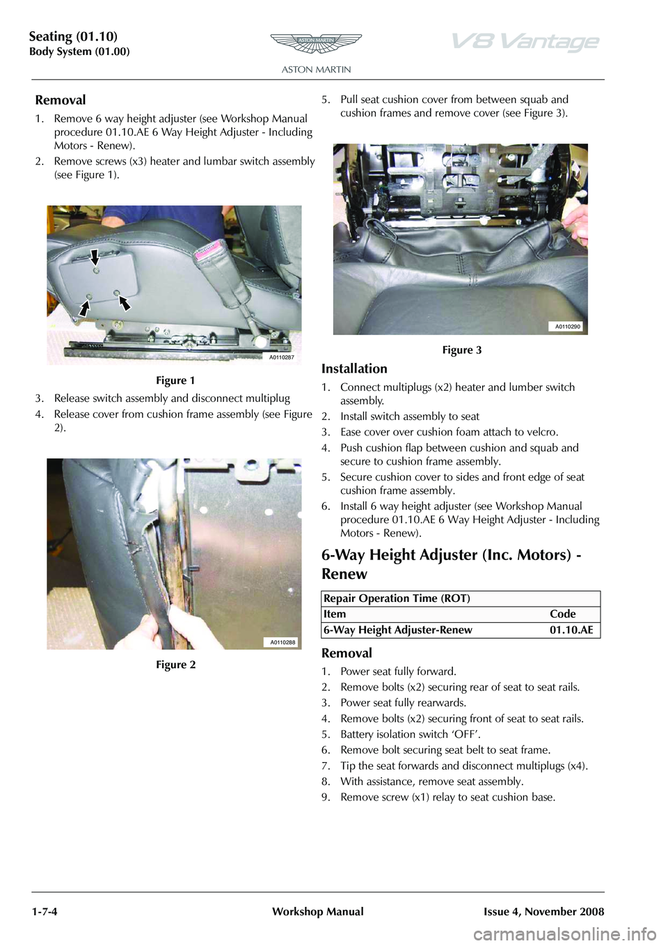
2. Remove screws (x3) heater and lumbar switch assembly
(see Figure 1).
3. Release switch assembly and disconnect multiplug
4. Release cover from cushion frame assembly (see Figure 2). 5. Pull seat cushion cover from between squab and
cushion frames and remove cover (see Figure 3).
Installation
1. Connect multiplugs (x2) heater and lumber switch assembly.
2. Install switch assembly to seat
3. Ease cover over cushion foam attach to velcro.
4. Push cushion flap between cushion and squab and secure to cushion frame assembly.
5. Secure cushion cover to sides and front edge of seat cushion frame assembly.
6. Install 6 way height adjust er (see Workshop Manual
procedure 01.10.AE 6 Way He ight Adjuster - Including
Motors - Renew).
6-Way Height Adjuster (Inc. Motors) -
Renew
Removal
1. Power seat fully forward.
2. Remove bolts (x2) securing rear of seat to seat rails.
3. Power seat fully rearwards.
4. Remove bolts (x2) securing front of seat to seat rails.
5. Battery isolation switch ‘OFF’.
6. Remove bolt securing seat belt to seat frame.
7. Tip the seat forwards and disconnect multiplugs (x4).
8. With assistance, remove seat assembly.
9. Remove screw (x1) relay to seat cushion base.
Figure 1
Figure 2
A0110287
A0110288
Figure 3
Repair Operation Time (ROT)
ItemCode
6-Way Height Adjuster-Renew 01.10.AE
A0110290
Page 72 of 947
Seating (01.10)
Body System (01.00)1-7-6 Workshop Manual Issue 4, November 2008
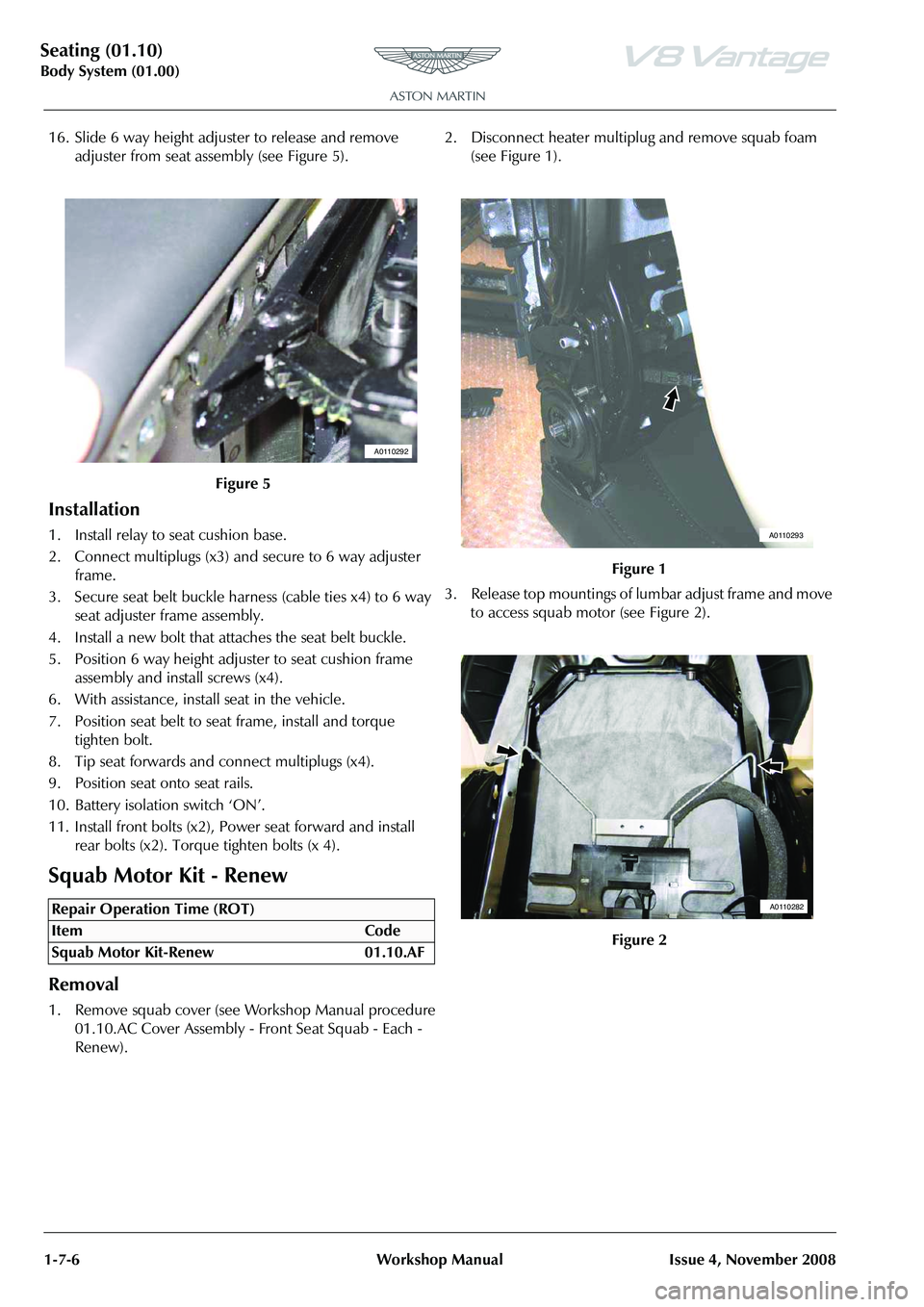
16. Slide 6 way height adjuster to release and remove adjuster from seat assembly (see Figure 5).
Installation
1. Install relay to seat cushion base.
2. Connect multiplugs (x3) and secure to 6 way adjuster frame.
3. Secure seat belt buckle harness (cable ties x4) to 6 way seat adjuster frame assembly.
4. Install a new bolt that attaches the seat belt buckle.
5. Position 6 way height adju ster to seat cushion frame
assembly and install screws (x4).
6. With assistance, install seat in the vehicle.
7. Position seat belt to seat frame, install and torque tighten bolt.
8. Tip seat forwards and connect multiplugs (x4).
9. Position seat onto seat rails.
10. Battery isolation switch ‘ON’.
11. Install front bolts (x2), Power seat forward and install rear bolts (x2). Torque tighten bolts (x 4).
Squab Motor Kit - Renew
Removal
1. Remove squab cover (see Workshop Manual procedure 01.10.AC Cover Assembly - Front Seat Squab - Each -
Renew). 2. Disconnect heater multiplug and remove squab foam
(see Figure 1).
3. Release top mountings of lumbar adjust frame and move to access squab motor (see Figure 2).
Figure 5
Repair Operation Time (ROT)
A0110292
Figure 1
Figure 2
A0110293
A0110282