O2 sensor ASTON MARTIN V8 VANTAGE 2010 Workshop Manual
[x] Cancel search | Manufacturer: ASTON MARTIN, Model Year: 2010, Model line: V8 VANTAGE, Model: ASTON MARTIN V8 VANTAGE 2010Pages: 947, PDF Size: 43.21 MB
Page 924 of 947
Aston Martin V12 Family
2009 MY V12 Family EOBDincl. V12 Vantage
Aston Martin/Ford Confidential
Component/ System Fault Code Monitor Strategy
Description Malfunction Criteria Threshold Parameter Secondary Parameters Entry Parameters Time Required DTC
StorageMIL Illumin-
ation
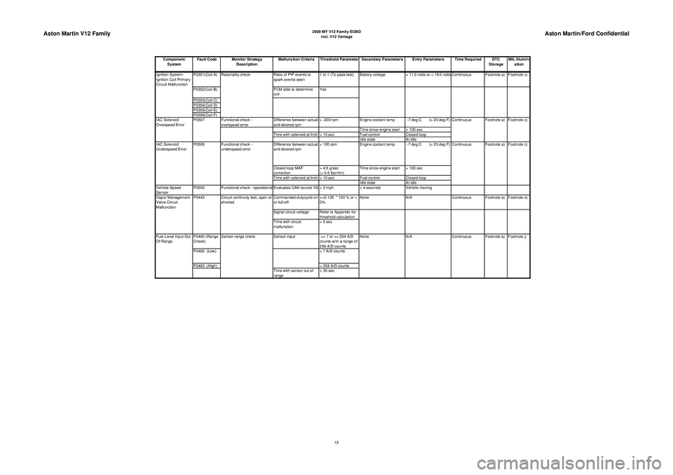
P0351(Coil A) Ratio of PIP events to
spark events seen 1 to 1 (To pass test) Battery voltage
> 11.0 volts or < 18.0 volts Continuous Footnote a) Footnote c)
P0352(Coil B) PCM able to determine
coil Yes
P0353(Coil C)
P0354(Coil D)
P0355(Coil E)
P0356(Coil F) Functional check -
overspeed error Difference between actual
and desired rpm> -200 rpm
Engine coolant temp -7 deg C (> 20 deg F)
Time since engine start > 100 sec
Time with solenoid at limit > 15 sec Fuel controlClosed loop
Idle state At idle
Difference between actual
and desired rpm > 100 rpm
Engine coolant temp -7 deg C (> 20 deg F)
Closed loop MAF
correction > 4.5 g/sec
(> 0.6 lbs/min)Time since engine start > 100 sec
Time with solenoid at limit > 10 sec Fuel controlClosed loop
Idle state At idle
Vehicle Speed
Sensor P0500 Functional check - operational Evaluates CAN source VS > 3 mph
> 4 secondsVehicle moving
Commanded dutycycle on
or full-off >=0.135 * 100 % or =
0%None
N/A Continuous Footnote a) Footnote e)
Signal circuit voltage Refer to Appendix for threshold calculation
Time with circuit
malfunction > 5 sec
P0460 (Range
Check) Sensor input
<= 7 or >= 254 A/D
counts w/in a range of
256 A/D counts
P0462 (Low) < 7 A/D counts
P0463 (High) > 254 A/D counts
Time with sensor out of
range > 30 sec N/A
Continuous Footnote a) Footnote j)
Fuel Level Input Out
Of Range Sensor range check
None
Vapor Management
Valve Circuit
Malfunction
P0443 Circuit continuity test, open or
shorted Footnote a) Footnote c)
IAC Solenoid
Underspeed Error P0506 Functional check -
underspeed error Continuous
IAC Solenoid
Overspeed Error
P0507
Continuous Footnote a) Footnote c)
Ignition System-
Ignition Coil Primary
Circuit Malfunction
Rationality check
13
Page 925 of 947
Aston Martin V12 Family
2009 MY V12 Family EOBDincl. V12 Vantage
Aston Martin/Ford Confidential
Component/ System Fault Code Monitor Strategy
Description Malfunction Criteria Threshold Parameter Secondary Parameters Entry Parameters Time Required DTC
StorageMIL Illumin-
ation
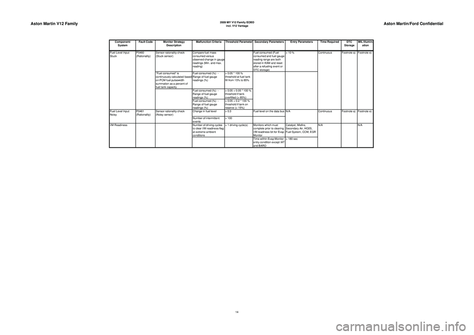
Sensor rationality check
(Stuck sensor) Compare fuel mass
consumed versus
observed change in gaug
e
readings (Min. and max.
reading) Fuel consumed (Fuel
consumed and fuel gauge
reading range are both
stored in KAM and reset
after a refueling event or
DTC storage)> 10 %
"Fuel consumed" is
continuously calculated based
on PCM fuel pulsewidth
summation as a percent of
fuel tank capacity Fuel consumed (%) -
Range of fuel gauge
readings (%)
> 0.05 * 100 %
threshold at fuel tank
fill from 15% to 85%
Fuel consumed (%) -
Range of fuel gauge
readings (%) > 0.05 + 0.05 * 100 %
threshold if tank
overfilled (> 85%)
Fuel consumed (%) -
Range of fuel gauge
readings (%) > 0.05 + 0.2 * 100 %
threshold if tank on
reserve (< 15%)
Change in fuel level > 0.3 Fuel level on the data bus
Number of intermittent
events > 100
Number of driving cycles
to clear I/M readiness flag
at extreme ambient
conditions > 1 driving cycle(s) Monitors which must
complete prior to clearing
I/M readiness bit for Evap
Monitor Catalyst, Misfire,
Secondary Air, HO2S,
Fuel System, CCM, EGR
Time within Evap Monitor
entry condition except IAT
and BARO > 180 sec N/A
I/M Readiness N/AFootnote e)
Fuel Level Input
Noisy P0461
(Rationality)Sensor rationality check
(Noisy sensor) N/A
Continuous Footnote a) Footnote e)
Continuous Footnote a)
Fuel Level Input
Stuck P0460
(Rationality)
14
Page 926 of 947
Aston Martin V12 Family
2009 MY V12 Family EOBDincl. V12 Vantage
Aston Martin/Ford Confidential
Component/ System Fault Code Monitor Strategy
Description Malfunction Criteria Threshold Parameter Secondary Parameters Entry Parameters Time Required DTC
StorageMIL Illumin-
ationTPPC chip failure in
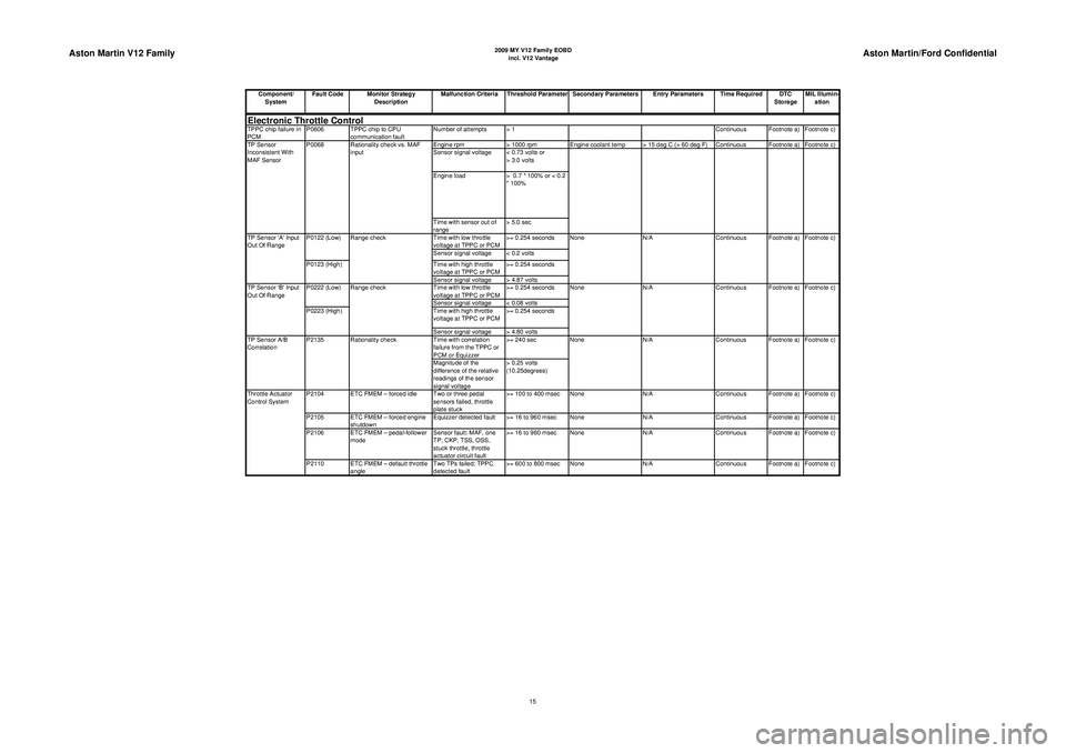
PCM P0606 TPPC chip to CPU
communication fault Number of attempts > 1
Continuous Footnote a) Footnote c)
Engine rpm > 1000 rpmEngine coolant temp > 15 deg C (> 60 deg F) Continuous Footnote a) Footnote c)
Sensor signal voltage < 0.73 volts or > 3.0 volts
Engine load > 0.7 * 100% or < 0.2
* 100%
Time with sensor out of
range > 5.0 sec
Time with low throttle
voltage at TPPC or PCM >= 0.254 seconds
Sensor signal voltage < 0.2 volts
Time with high throttle
voltage at TPPC or PCM >= 0.254 seconds
Sensor signal voltage > 4.87 volts
Time with low throttle
voltage at TPPC or PCM >= 0.254 seconds
Sensor signal voltage < 0.08 volts
Time with high throttle
voltage at TPPC or PCM >= 0.254 seconds
Sensor signal voltage > 4.80 volts
Time with correlation
failure from the TPPC or
PCM or Equizzer >= 240 sec
Magnitude of the
difference of the relative
readings of the sensor
signal voltage > 0.25 volts
(10.25degrees)
P2104 ETC FMEM – forced idle Two or three pedal sensors failed, throttle
plate stuck>= 100 to 400 msec None
N/AContinuous Footnote a) Footnote c)
P2105 ETC FMEM – forced engine shutdown Equizzer detected fault >= 16 to 960 msec None
N/AContinuous Footnote a) Footnote c)
P2106 ETC FMEM – pedal-follower mode Sensor fault: MAF, one
TP, CKP, TSS, OSS,
stuck throttle, throttle
actuator circuit fault>= 16 to 960 msec None
N/AContinuous Footnote a) Footnote c)
P2110 ETC FMEM – default throttle angle Two TPs failed; TPPC
detected fault>= 600 to 800 msec None
N/AContinuous Footnote a) Footnote c)
Throttle Actuator
Control SystemElectronic Throttle ControlTP Sensor A/B
Correlation
P2135 Rationality check None N/A Continuous Footnote a) Footnote c) Footnote c)
TP Sensor 'B' Input
Out Of Range P0222 (Low)
P0223 (High)Range check None N/A Continuous Footnote a) Footnote c) None N/A Continuous Footnote a)
TP Sensor 'A' Input
Out Of Range P0122 (Low)
P0123 (High)Range check
TP Sensor
Inconsistent With
MAF Sensor
P0068 Rationality check vs. MAF
input
15
Page 931 of 947
Aston Martin V12 Family
2009 MY V12 Family EOBDincl. V12 Vantage
Aston Martin/Ford Confidential
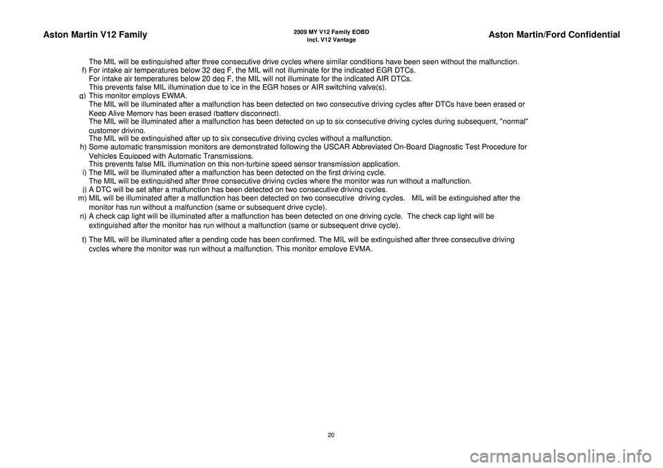
The MIL will be extin
guished after three consecutive drive c
ycles where similar conditions have been seen without the malfunction.
f
)For intake air tem
peratures below 32 de
g F, the MIL will not illuminate for the indicated EGR DTCs.
For intake air tem
peratures below 20 de
g F, the MIL will not illuminate for the indicated AIR DTCs.
This
prevents false MIL illumination due to ice in the EGR hoses or AIR switchin
g valve
(s).
g)
This monitor em
ploys EWMA.
The MIL will be illuminated after a malfunction has been detected on two consecutive driving cycles after DTCs have been erased or
Kee
p Alive Memor
y has been erased
(batter
y disconnect
).
The MIL will be illuminated after a malfunction has been detected on up to six consecutive driving cycles during subsequent, "normal"
customer drivin
g.
The MIL will be extin
guished after u
p to six consecutive drivin
g cycles without a malfunction.
h) Some automatic transmission monitors are demonstrated following the USCAR Abbreviated On-Board Diagnostic Test Procedure for
Vehicles E
quipp
ed with Automatic Transmissions.
This
prevents false MIL illumination on this non-turbine s
peed sensor transmission a
pp
lication.
i
)The MIL will be illuminated after a malfunction has been detected on the first drivin
g cycle.
The MIL will be extin
guished after three consecutive drivin
g cycles where the monitor was run without a malfunction.
j)A DTC will be set after a malfunction has been detected on two consecutive drivin
g cycles.
m) MIL will be illuminated after a malfunction has been detected on two consecutive driving cycles. MIL will be extinguished after the
monitor has run without a malfunction
(same or subse
quent drive c
ycle
).
n) A check cap light will be illuminated after a malfunction has been detected on one driving cycle. The check cap light will be
extinguished after the monitor has run without a malfunction (same or subsequent drive cycle).
t) The MIL will be illuminated after a pending code has been confirmed. The MIL will be extinguished after three consecutive driving c
ycles where the monitor was run without a malfunction. This monitor em
ploye EVMA.
20
Page 933 of 947
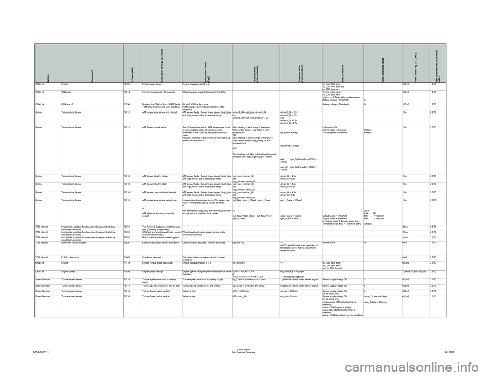
System
Component
P Codes (AML)
Malfunction Strategy Description
Malfunction Criteria
(Fault)
Fault condition
(Internal labels)
Threshold Value
(Fault condition)
Entry conditions
Entry conditions values
Filter Time to log DTC (AML)
EMS controlled MIL Illumination
(AML)
CAN LinkEngine P0725Engine speed signal
Engine Speed signal QF ≠ 3 No CAN BUS error.
No CAN level error and
No EMS timeout.600mS
1 DTC
CAN Link CAN level P0614Incorrect configuration ID received CANid does not match that stored in the TCM Engine not in crank.
No CAN BUS error
Ignition on & Timer after ignition passed.
Battery Voltage > threshold7v250mS
1 DTC
CAN Link CAN bus off P1796Monitors the CAN for Bus or RAM faults.
TCM CAN driver detects CAN bus fault. Bit, stuff, CRC or form error,
(CAN-wiring or CAN-module defective, EMC
radiation.) Battery voltage > Threshold
7v100mS1 DTC
Sensor Temperature Sensor P0711 ATF temperature sensor short circuit ATF sensor faulty - Sensor input signals (Vcgt_plus
and Vcgt_minus) out of acceptable range utmsm2_Gt
utmsm2_Gt
and
utmsm2_Gt =2.3v
utmsm1_Gt =2.7v 1.5s
2 DTC
Sensor Temperature Sensor P0711ATF Sensor - stuck value Stuck Temperature value - ATF temperature is out
of an acceptable range of tolerance when
compared to the TCM chip temperature sensor
value.
Range of tolerance is depending on the heating up
velocity of transmission . [
Fast heating = wide range of tolerance :
Chip sensor temp +/- cgt_tolwt <> ATF
temperature
OR
Slow heating = narrow range of tolerance :
Chip sensor temp +/- cgt_toleng <> ATF
temperature.]
AND
Temperature cgtf_Neu out of allowed range of
tolerance for > zgts_CgtPlausiErr * 100ms cgt_tolwt = 40degC
cgt_toleng = 25degC
AML: zgts_CgtPlausiErr= 6000 ( =
10min)
Jag+LR: zgts_CgtPlausiErr= 9000 ( =
15min)Chip sensor OK
Engine speed > threshold
Turbine speed > threshold
450rpm
450rpm1.5s
2 DTC
Sensor Temperature Sensor P0713ATF Sensor short to battery ATF sensor faulty - Sensor input signals (Vcgt_plus
and Vcgt_minus) out of acceptable range vcgt_plus > utmso_Gt
and
vcgt_minus > utmsu_Gtutmso_Gt = 4.5v
utmsu_Gt =0.5v
1.5s
2 DTC
Sensor Temperature Sensor P0712ATF Sensor short to GND ATF sensor faulty - Sensor input signals (Vcgt_plus
and Vcgt_minus) out of acceptable range vcgt_plus < utmso_Gt
and
vcgt_minus < utmsu_Gtutmso_Gt = 4.5v
utmsu_Gt =0.5v
1.5s
2 DTC
Sensor Temperature Sensor P0714ATF sensor open cct (circuit break) ATF sensor faulty - Sensor input signals (Vcgt_plus
and Vcgt_minus) out of acceptable range vcgt_plus > utmso_Gt
and
vcgt_minus < utmsu_Gtutmso_Gt = 4.5v
utmsu_Gt =0.5v
1.5s
2 DTC
Sensor Temperature Sensor P0713 ATF temperature sensor value jump
or
ATF value not warming up quickly
enough Unacceptable temperature jump (lOld value - new
value <> threshold) within a period of 100ms
or
ATF temperature (cgt_neu) not warming up quickly
enough within a specified time period
|cgt_Neu - cgta1_CUew| > cgtd1_Cuew
or
(cgt_Neu(t=tgtd_CUew) - cgt_Neu(t=0) ) <
cgtd2_Cuewcgtd1_Cuew = 20DegC
cgtd2_Cuew = 4DegC
tgtd_CUEW = 240s
Output speed > Threshold
Engine speed > Threshold
No Output speed & Engine speed error
Temperature cgt_Neu < Threshold at t=0Jag +
AML / LR
800 / 11000rpm
400 / 11000rpm
20DegC1.5s
2 DTC
TCM Internal Impossible substitute functions (monitoring contradictory
substitute functions) P0701
Two Priority 2 faults present at the same
time (Currently not possible) 20ms
2 DTC
TCM Internal Impossible substitute functions (monitoring contradictory
substitute functions) P0701
OSS fault and wheel speed faults present
concurrently (Priority 3) Wheel speed and output speed sensor faults
present concurrently. 20ms
2 DTC
TCM Internal Impossible substitute functions (monitoring contradictory
substitute functions) P0701
Bosch solenoid current monitorin
g fault 20ms 2 DTC
TCM Internal EEPROM Flash emulation P062FEEPROM emulation lifetime exceeded Communication disturbed, lifetime exceeded EEError !=0 =1
400000 Write/Erase-cycles possible. At
temperatures over 135°C no EEProm
update is made.always active
no0mS1 DTC
TCM Internal FLASH checksum P1603Checksum incorrect Calculated checksum does not match stored
checksum 0mS
2 DTC
CAN Link Engine P1719Engine Torque signal inaccurate
Engine torque signal QF 0 = 3 fcn_MmmErr
=1No CAN BUS error.
No CAN level error
and No EMS timeout. 600ms
2 DTC
CAN Link Engine Speed P1920Engine speed too high Engine Speed > Engine speed threshold> for a time
threshold n_mot > NS_MOTUEB
&
Timer_nmotueb > T_FNMOTUEBNS_MOTUEB = 7100rpm
T_FNMOTUEB=2550mS T_FNMOTUEB=2550mS 2 DTC
Speed Sensors Turbine speed sensor P0715Turbine speed sensor s/c to battery
supply Turbine speed sensor s/c to battery supply sgt_DiNtu = 2 (short circuit to plus)
2 (Status of turbine speed sensor signal. Sensor supply voltage OK0600mS2 DTC
Speed Sensors Turbine speed sensor P0717Turbine speed sensor s/c to gnd or O/C Turbine speed sensor s/c to gnd or O/C sgt_DiNtu = 0 (short to gnd or OC)0 (Status of turbine speed sensor signal. Sensor supply voltage OK 0600mS2 DTC
Speed Sensors Turbine speed sensor P0716Turbine Speed Value too high Value too high NTU >= NTUmaxntumax = 8000rpmSensor supply voltage OK
No electrical error 0
600mS2 DTC
Speed Sensors Turbine speed sensor P0716Turbine Speed Value too low Value too low NTU < ntu_Minntu_min = 20 rpmSensor supply voltage OK
No electrical error
engine speed NMO is higher than a
threshold:
status of NMO-signal is alright
output speed NAB is higher than a
threshold:
status of NAB-signal is alright or substitute
fltfl fb Ei t t
nmos_TuUew = 600rpm
nabs_TuUew = 250rpm 600mS
2 DTC
8ASXV05.9VH1 Aston Martin
Auto Gearbox Summary Jan 2008
Page 934 of 947
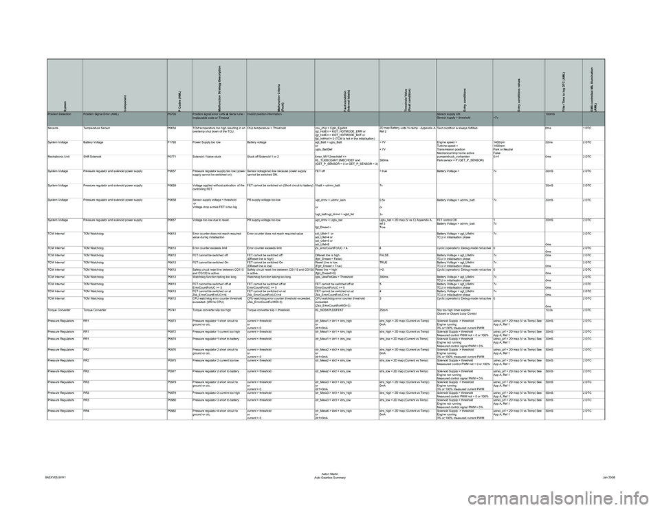
System
Component
P Codes (AML)
Malfunction Strategy Description
Malfunction Criteria
(Fault)
Fault condition
(Internal labels)
Threshold Value
(Fault condition)
Entry conditions
Entry conditions values
Filter Time to log DTC (AML)
EMS controlled MIL Illumination
(AML)
y volts Vs temp - Appendix A,
Ref 2 Test condition is always fulfilled. 0ms 1 DTC
System Voltage Battery Voltage P1793 Power Supply too low Battery voltage ugt_Batt < ugtu_Batt or
ugtu_BattDef< 7V
< 7VEngine speed >
Turbine speed >
Transmission position
Mechanical limp home active1400rpm
1400rpm
Park or Neutral
False30ms
2 DTC
Mechatronic Unit Shift Solenoid P0771Solenoid / Valve stuck Stuck off Solenoid 1 or 2 timer_MV12mechdef <=
KL_TUEBCGMV12MECHDEF and
(GET_P_SENSOR = 0 or GET_P_SENSOR = 2) 500mspumpendruck_vorhanden
Park sensor = P (GET_P_SENSOR)0->1
0ms2 DTC
System Voltage Pressure regulator and solenoid power supply P0657Pressure regulator supply too low (power
supply cannot be switched on) Sensor voltage too low because power supply
cannot be switched ON. FET off
= trueBattery Voltage > 7v30mS2 DTC
System Voltage Pressure regulator and solenoid power supply P0659Voltage applied without activation of the
controlling FET FET cannot be switched on (Short circuit to battery) Vbatt > udrmv_batt
7v 30mS2 DTC
System Voltage Pressure regulator and solenoid power supply P0658Sensor supply voltage < threshold
or
Voltage drop across FET is too big PR supply voltage too low
u
gt_drmv < udrmv_ksm
or
lugt_batt-ugt_drmvl > ugtd_fet 0.5v
or
1vBattery Voltage > udrmv_batt
7v30mS2 DTC
System Voltage Pressure regulator and solenoid power supply P0657Voltage too low due to reset. PR supply voltage too low ugt_drmv < Ugtu_bat
fgt_Dreset = Ugtu_bat = 2D map (V vs C) Appendix A,
ref 3
TrueFET control OK
Battery Voltage > udrmv_batt
1
7v30mS
2 DTC
TCM Internal TCM Watchdog P0613Error counter does not reach required
value during initialisation Error counter does not reach required value sdi_Ufet=1 or
sdi_Ufet=4 or
sdi_Ufet=5 or
sdi_Ufet=8 Battery Voltage > ugt_UfetIni
TCU in initialisation phase
7v
0ms2 DTC
TCM Internal TCM Watchdog P0613Error counter exceeds limit Error counter exceeds limit Zs_errorCountForUC > 4.4Cyclic (operation): Debug-mode not active 0
0ms2 DTC
TCM Internal TCM Watchdog P0613FET cannot be switched off FET cannot be switched off
(DReset line is high) DReset line is high
(fgtr_Dreset = False)FALSE
Battery Voltage > ugt_UfetIni
TCU in initialisation phase7v
0ms2 DTC
TCM Internal TCM Watchdog P0613FET cannot be switched On FET cannot be switched On
(DReset line is low) Reset Line is low.
(Fgtr_Dreset = True)TRUE
Battery Voltage > ugt_UfetIni
TCU in initialisation phase7v
0ms2 DTC
TCM Internal TCM Watchdog P0613Safety circuit reset line between CG115
and CG120 is active. Safety circuit reset line between CG115 and CG120
is active. Reset line = high
(fgtr_Dreset!=0)!=0
Cyclic (operation): Debug-mode not active 0
0ms2 DTC
TCM Internal TCM Watchdog P0613Watchdog function taking too long. Watchdog function taking too long. tgts_UewFetGes > Threshold300msBattery Voltage > ugt_UfetIni
TCU in initialisation phase7v
0ms2 DTC
TCM Internal TCM Watchdog P0613FET cannot be switched off at
ErrorCountForUC >= 5 FET cannot be switched off at
ErrorCountForUC >= 5 FET cannot be switched off at
ErrorCountForUC >= 55
Battery Voltage > ugt_UfetIni
TCU in initialisation phase7v
0ms2 DTC
TCM Internal TCM Watchdog P0613FET cannot be switched on at
Zsk_ErrorCountForUC<=4 FET cannot be switched on at
Zsk_ErrorCountForUC<=4 FET cannot be switched on at
Zsk_ErrorCountForUC<=44
Battery Voltage > ugt_UfetIni
TCU in initialisation phase7v
0ms2 DTC
TCM Internal TCM Watchdog P0613CPU watchdog error counter threshold
exceeded. (WD to CPU) CPU watchdog error counter threshold exceeded.
(Zsk_ErrorCountForWD>3) CPU watchdog error counter threshold
exceeded.
(Zsk_ErrorCountForWD>3)3
Cyclic (operation): Debug-mode not active 0
0ms2 DTC
Torque Converter Torque Converter P0741Torque converter slip too high Torque converter slip > threshold. KL_NDSKPLDEFEKT25rpmSlip too high timer expired
Closed or Closed Loop Control 10.0s
2 DTC
Pressure Regulators PR1 P0973Pressure regulator 1 short circuit to
ground or o/c. current > threshold
or
current = 0 idr_Mess1 > idr1 + idrs_high
or
idr1=0mAidrs_high = 2D map (Current vs Temp)
0mA
Solenoid Supply > threshold
Engine running
0% or 100% measured current PWMudrso_prf = 2D map (V vs Temp) See
App A, Ref 1
30mS
2 DTC
Pressure Regulators PR1 P0972Pressure regulator 1 current too high current > threshold idr_Mess1 > idr1 + idrs_highidrs_high = 2D map (Current vs Temp) Solenoid Supply > threshold
Measured control PWM not = 0 or 100%udrso_prf = 2D map (V vs Temp) See
App A, Ref 130mS
2 DTC
Pressure Regulators PR1 P0974Pressure regulator 1 short to battery current < threshold idr_Mess1 < idr1 + idrs_lowidrs_low = 2D map (Current vs Temp) Solenoid Supply > threshold
Engine not running
Measured control signal PWM = 0%udrso_prf = 2D map (V vs Temp) See
App A, Ref 1
30mS
2 DTC
Pressure Regulators PR2 P0976Pressure regulator 2 short circuit to
ground or o/c. current > threshold
or
current = 0 idr_Mess2 > idr2 + idrs_high
or
idr1=0mAidrs_high = 2D map (Current vs Temp)
0mA
Solenoid Supply > threshold
Engine running
0% or 100% measured current PWMudrso_prf = 2D map (V vs Temp) See
App A, Ref 1
50mS
2 DTC
Pressure Regulators PR2 P0975Pressure regulator 2 current too low current < threshold idr_Mess2 < idr2 + idrs_lowidrs_low = 2D map (Current vs Temp) Solenoid Supply > threshold
Meassured control PWM not = 0 or 100%udrso_prf = 2D map (V vs Temp) See
App A, Ref 150mS
2 DTC
Pressure Regulators PR2 P0977Pressure regulator 2 short to battery current < threshold idr_Mess2 < idr2 + idrs_lowidrs_low = 2D map (Current vs Temp) Solenoid Supply > threshold
Engine not running
Measured control signal PWM = 0%udrso_prf = 2D map (V vs Temp) See
App A, Ref 1
50mS
2 DTC
Pressure Regulators PR3 P0979Pressure regulator 3 short circuit to
ground or o/c. current > threshold
or
current = 0 idr_Mess3 > idr3 + idrs_high
or
idr1=0mAidrs_high = 2D map (Current vs Temp)
0mA
Solenoid Supply > threshold
Engine running
0% or 100% measured current PWMudrso_prf = 2D map (V vs Temp) See
App A, Ref 1
50mS
2 DTC
Pressure Regulators PR3 P0978Pressure regulator 3 current too high current > threshold idr_Mess3 > idr3 + idrs_highidrs_high = 2D map (Current vs Temp) Solenoid Supply > threshold
Measured control PWM not = 0 or 100%udrso_prf = 2D map (V vs Temp) See
App A, Ref 150mS
2 DTC
Pressure Regulators PR3 P0980Pressure regulator 3 short to battery current < threshold idr_Mess3 < idr3 + idrs_lowidrs_low = 2D map (Current vs Temp) Solenoid Supply > threshold
Engine not running
Measured control signal PWM = 0%udrso_prf = 2D map (V vs Temp) See
App A, Ref 1
50mS
2 DTC
Pressure Regulators PR4 P0982Pressure regulator 4 short circuit to
ground or o/c. current > threshold
or
current = 0 idr_Mess4 > idr4 + idrs_high
or
idr1=0mAidrs_high = 2D map (Current vs Temp)
0mA
Solenoid Supply > threshold
Engine running
0% or 100% measured current PWMudrso_prf = 2D map (V vs Temp) See
App A, Ref 1
50mS
2 DTC
8ASXV05.9VH1 Aston Martin
Auto Gearbox Summary Jan 2008
Page 936 of 947
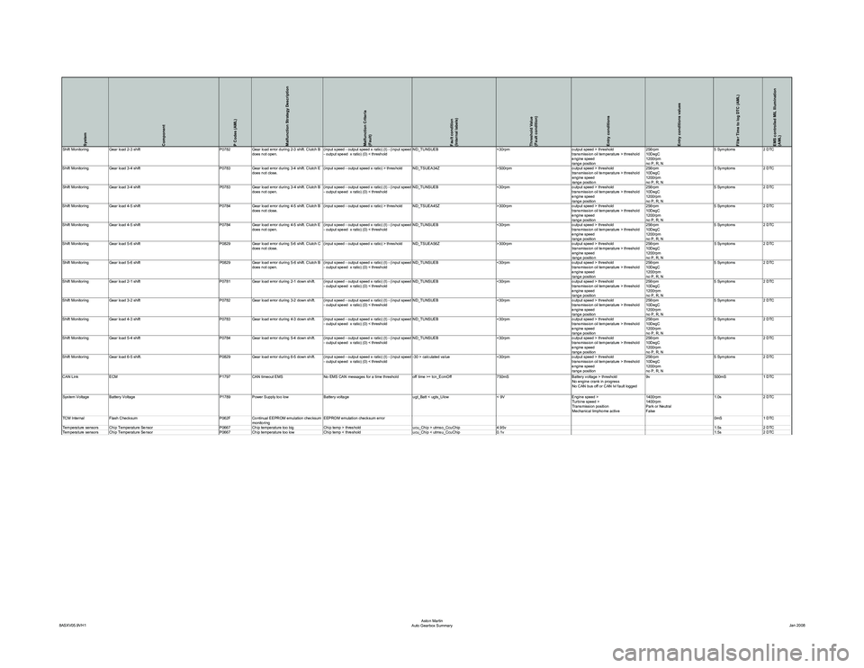
System
Component
P Codes (AML)
Malfunction Strategy Description
Malfunction Criteria
(Fault)
Fault condition
(Internal labels)
Threshold Value
(Fault condition)
Entry conditions
Entry conditions values
Filter Time to log DTC (AML)
EMS controlled MIL Illumination
(AML)
(input speed - output speed x ratio
) (t) - (input speed
- output speed x ratio) (0) < threshold ND_TUNSUEB
<30rpmoutput speed > threshold
transmission oil temperature > threshold
engine speed
range position 256rpm
10DegC
1200rpm
no P, R, N5 Symptoms
2 DTC
Shift Monitoring Gear load 4-5 shift P0784Gear load error during 4-5 shift. Clutch B
does not close. (input speed - output speed x ratio) > threshold ND_TSUEA45Z
>300rpmoutput speed > threshold
transmission oil temperature > threshold
engine speed
range position 256rpm
10DegC
1200rpm
no P, R, N5 Symptoms
2 DTC
Shift Monitoring Gear load 4-5 shift P0784Gear load error during 4-5 shift. Clutch E
does not open.
(input speed - output speed x ratio
) (t) - (input speed
- output speed x ratio) (0) < threshold ND_TUNSUEB
<30rpmoutput speed > threshold
transmission oil temperature > threshold
engine speed
range position 256rpm
10DegC
1200rpm
no P, R, N5 Symptoms
2 DTC
Shift Monitoring Gear load 5-6 shift P0829Gear load error during 5-6 shift. Clutch C
does not close. (input speed - output speed x ratio) > threshold ND_TSUEA56Z
>300rpmoutput speed > threshold
transmission oil temperature > threshold
engine speed
range position 256rpm
10DegC
1200rpm
no P, R, N5 Symptoms
2 DTC
Shift Monitoring Gear load 5-6 shift P0829Gear load error during 5-6 shift. Clutch B
does not open.
(input speed - output speed x ratio
) (t) - (input speed
- output speed x ratio) (0) < threshold ND_TUNSUEB
<30rpmoutput speed > threshold
transmission oil temperature > threshold
engine speed
range position 256rpm
10DegC
1200rpm
no P, R, N5 Symptoms
2 DTC
Shift Monitoring Gear load 2-1 shift P0781Gear load error during 2-1 down shift.
(input speed - output speed x ratio
) (t) - (input speed
- output speed x ratio) (0) < threshold ND_TUNSUEB
<30rpmoutput speed > threshold
transmission oil temperature > threshold
engine speed
range position 256rpm
10DegC
1200rpm
no P, R, N5 Symptoms
2 DTC
Shift Monitoring Gear load 3-2 shift P0782Gear load error during 3-2 down shift.
(input speed - output speed x ratio
) (t) - (input speed
- output speed x ratio) (0) < threshold ND_TUNSUEB
<30rpmoutput speed > threshold
transmission oil temperature > threshold
engine speed
range position 256rpm
10DegC
1200rpm
no P, R, N5 Symptoms
2 DTC
Shift Monitoring Gear load 4-3 shift P0783Gear load error during 4-3 down shift.
(input speed - output speed x ratio
) (t) - (input speed
- output speed x ratio) (0) < threshold ND_TUNSUEB
<30rpmoutput speed > threshold
transmission oil temperature > threshold
engine speed
range position 256rpm
10DegC
1200rpm
no P, R, N5 Symptoms
2 DTC
Shift Monitoring Gear load 5-4 shift P0784Gear load error during 5-4 down shift.
(input speed - output speed x ratio
) (t) - (input speed
- output speed x ratio) (0) < threshold ND_TUNSUEB
<30rpmoutput speed > threshold
transmission oil temperature > threshold
engine speed
range position 256rpm
10DegC
1200rpm
no P, R, N5 Symptoms
2 DTC
Shift Monitoring Gear load 6-5 shift. P0829Gear load error during 6-5 down shift.
(input speed - output speed x ratio
) (t) - (input speed
- output speed x ratio) (0) < threshold -30 > calculated value
<30rpmoutput speed > threshold
transmission oil temperature > threshold
engine speed
range position 256rpm
10DegC
1200rpm
no P, R, N5 Symptoms
2 DTC
CAN Link ECM P1797CAN timeout EMS No EMS CAN messages for a time threshold off time >= tcn_EcmOff 750mSBattery voltage > threshold
No engine crank in progress
No CAN bus off or CAN lvl fault logged 9v
500mS1 DTC
System Voltage Battery Voltage P1789Power Supply too low Battery voltage ugt_Batt < ugts_Ulow< 9VEngine speed >
Turbine speed >
Transmission position
Mechanical limphome active 1400rpm
1400rpm
Park or Neutral
False1.0s
2 DTC
TCM Internal Flash Checksum P062FContinual EEPROM emulation checksum
monitoring EEPROM emulation checksum error
0mS1 DTC
Temperature sensors Chip Temperature Sensor P0667 Chip temperature too big Chip temp > threshold ucu_Chip > utmso_CcuChip4.95v 1.5s2 DTC
Temperature sensors Chip Temperature Sensor P0667 Chip temperature too low Chip temp < threshold ucu_Chip < utmsu_CcuChip0.1v 1.5s2 DTC
8ASXV05.9VH1 Aston Martin
Auto Gearbox Summary Jan 2008