fuel pump ASTON MARTIN V8 VANTAGE 2010 Owner's Manual
[x] Cancel search | Manufacturer: ASTON MARTIN, Model Year: 2010, Model line: V8 VANTAGE, Model: ASTON MARTIN V8 VANTAGE 2010Pages: 947, PDF Size: 43.21 MB
Page 869 of 947
AML EOBD System Operation Summary
Rory O’Curry Aston Martin Lagonda CONFIDENTIAL 1 May 2009
[email protected] AML EOBD Monitors 07 ROC.doc Page 23 of 43
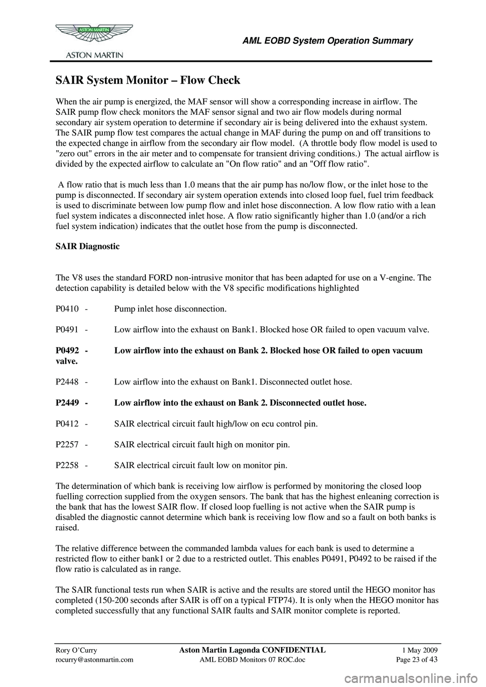
SAIR System Monitor – Flow Check
When the air pump is energized, the MAF sensor will show a corresponding increase in airflow. The
SAIR pump flow check monitors the MAF sensor signal and two air flow models during normal
secondary air system operation to determine if secondary air is being delivered into the exhaust system.
The SAIR pump flow test compares the actual change in MAF during the pump on and off transitions to
the expected change in airflow from the secondary air fl ow model. (A throttle body flow model is used to
"zero out" errors in the air meter and to compensate fo r transient driving conditions.) The actual airflow is
divided by the expected airflow to calculate an "On flow ratio" and an "Off flow ratio".
A flow ratio that is much less than 1.0 means that the air pump has no/low flow, or the inlet hose to the
pump is disconnected. If secondary air system operation ex tends into closed loop fuel, fuel trim feedback
is used to discriminate between low pump flow and in let hose disconnection. A low flow ratio with a lean
fuel system indicates a disconnected inlet hose. A flow ratio significantly higher than 1.0 (and/or a rich
fuel system indication) indicates that th e outlet hose from the pump is disconnected.
SAIR Diagnostic
The V8 uses the standard FORD non-intrusive monitor that has been adapted for use on a V-engine. The
detection capability is detailed below with the V8 specific modifications highlighted
P0410 - Pump inlet hose disconnection.
P0491 - Low airflow into the exhaust on Bank1. Blocked hose OR failed to open vacuum valve.
P0492 - Low airflow into the exhaust on Bank 2. Blocked hose OR failed to open vacuum
valve.
P2448 - Low airflow into the exhaust on Bank1. Disconnected outlet hose.
P2449 - Low airflow into the exhaust on Bank 2. Disconnected outlet hose.
P0412 - SAIR electrical circuit fault high/low on ecu control pin.
P2257 - SAIR electrical circuit fault high on monitor pin.
P2258 - SAIR electrical circuit fault low on monitor pin.
The determination of which bank is receiving low ai rflow is performed by monitoring the closed loop
fuelling correction supplied from the oxygen sensors. The bank that has the highest enleaning correction is
the bank that has the lowest SAIR flow. If closed loop fuelling is not active when the SAIR pump is
disabled the diagnostic cannot determ ine which bank is receiving low flow and so a fault on both banks is
raised.
The relative difference between the commanded lambda values for each bank is used to determine a
restricted flow to either bank1 or 2 due to a restricted outlet. This enables P0491, P0492 to be raised if the
flow ratio is calculated as in range.
The SAIR functional tests run when SAIR is active and the results are stored until the HEGO monitor has
completed (150-200 seconds after SAIR is off on a typical FTP74). It is only when the HEGO monitor has
completed successfully that any functional SAIR fa ults and SAIR monitor complete is reported.
Page 870 of 947
AML EOBD System Operation Summary
Rory O’Curry Aston Martin Lagonda CONFIDENTIAL 1 May 2009
[email protected] AML EOBD Monitors 07 ROC.doc Page 24 of 43
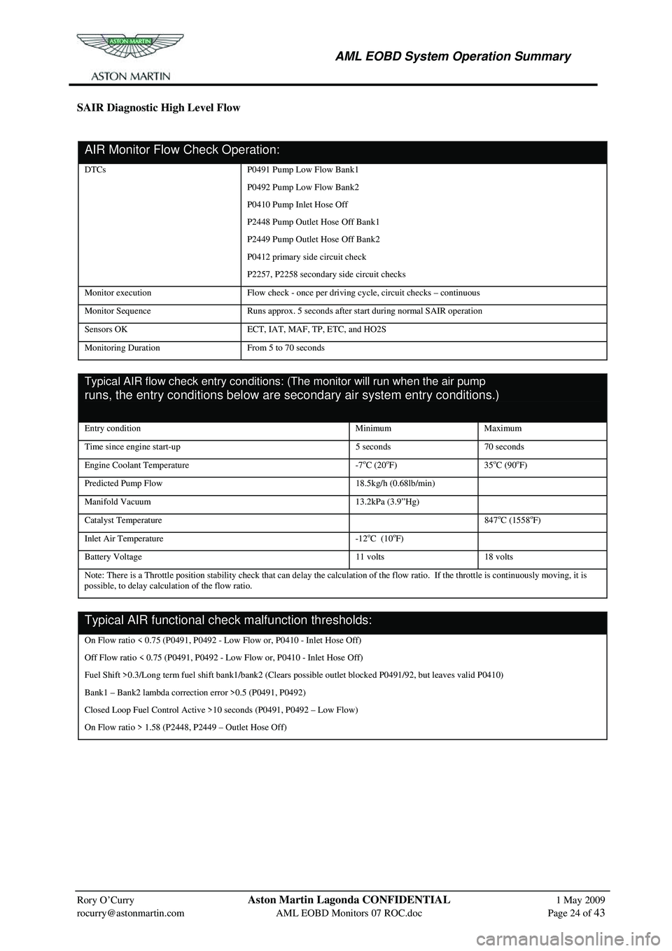
SAIR Diagnostic High Level Flow
AIR Monitor Flow Check Operation: onitor Flow Check Operation:
DTCs P0491 Pump Low Flow Bank1
P0492 Pump Low Flow Bank2
P0410 Pump Inlet Hose Off
P2448 Pump Outlet Hose Off Bank1
P2449 Pump Outlet Hose Off Bank2
P0412 primary side circuit check
P2257, P2258 secondary side circuit checks
Monitor execution Flow check - once per driving cycle, circuit checks – continuous
Monitor Sequence Runs approx. 5 seconds after start during normal SAIR operation
Sensors OK ECT, IAT, MAF, TP, ETC, and HO2S
Monitoring Duration From 5 to 70 seconds
Typical AIR flow check entry conditions: (The monitor will run when the air pump
runs, the entry conditions below are secondary air system entry conditions.) re secondary air
system entry conditions.)
Entry condition Minimum Maximum
Time since engine start-up 5 seconds 70 seconds
Engine Coolant Temperature -7oC (20oF) 35oC (90oF)
Predicted Pump Flow 18.5kg/h (0.68lb/min)
Manifold Vacuum 13.2kPa (3.9”Hg)
Catalyst Temperature 847oC (1558oF)
Inlet Air Temperature -12oC (10oF)
Battery Voltage 11 volts 18 volts
Note: There is a Throttle position stability ch eck that can delay the calculation of the flow ratio. If the throttle is continuously moving, it is
possible, to delay calculation of the flow ratio.
Typical AIR functional check malfunction thresholds:heck malfunction thresholds:
On Flow ratio < 0.75 (P0491, P0492 - Low Flow or, P0410 - Inlet Hose Off)
Off Flow ratio < 0.75 (P0491, P0492 - Lo w Flow or, P0410 - Inlet Hose Off)
Fuel Shift >0.3/Long term fuel shift bank1/bank2 (Clears possible outlet blocked P0491/92, but leaves valid P0410)
Bank1 – Bank2 lambda correcti on error >0.5 (P0491, P0492)
Closed Loop Fuel Control Active >10 seconds (P0491, P0492 – Low Flow)
On Flow ratio > 1.58 (P2448, P2449 – Outlet Hose Off)
Page 884 of 947
AML EOBD System Operation Summary
Rory O’Curry Aston Martin Lagonda CONFIDENTIAL 1 May 2009
[email protected] AML EOBD Monitors 07 ROC.doc Page 39 of 43
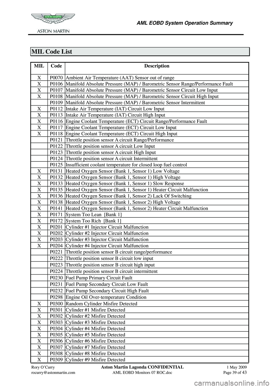
MIL Code List
MIL Code Description
X P0070 Ambient Air Temperature (AAT) Sensor out of range
X P0106 Manifold Absolute Pressure (MAP) / Barometric Sensor Range/Performance Fault
X P0107 Manifold Absolute Pressure (MAP) / Barometric Sensor Circuit Low Input
X P0108 Manifold Absolute Pressure (MAP) / Barometric Sensor Circuit High Input
P0109 Manifold Absolute Pressure (MAP) / Barometric Sensor Intermittent
X P0112 Intake Air Temperature (IAT) Circuit Low Input
X P0113 Intake Air Temperature (IAT) Circuit High Input
X P0116 Engine Coolant Temperature (ECT) Circuit Range/Performance Fault
X P0117 Engine Coolant Temperature (ECT) Circuit Low Input
X P0118 Engine Coolant Temperature (ECT) Circuit High Input
P0121 Throttle position sensor A circuit Range/Performance
P0122 Throttle position sensor A circuit Low Input
P0123 Throttle position sensor A circuit High Input
P0124 Throttle position sensor A circuit Intermittent
P0125 Insufficient coolant temperature for closed loop fuel control
X P0131 Heated Oxygen Sensor (Bank 1, Sensor 1) Low Voltage
X P0132 Heated Oxygen Sensor (Bank 1, Sensor 1) High Voltage
X P0133 Heated Oxygen Sensor (Ba nk 1, Sensor 1) Slow Response
X P0135 Heated Oxygen Sensor (Bank 1, Sensor 1) Heater Circuit Malfunction
X P0136 Heated Oxygen Sensor (Bank 1, Sensor 2) Lack Of Switching
X P0138 Heated Oxygen Sensor (Bank 1, Sensor 2) High Voltage
X P0141 Heated Oxygen Sensor (Bank 1, Sensor 2) Heater Circuit Malfunction
X P0171 System Too Lean [Bank 1]
X P0172 System Too Rich [Bank 1]
X P0201 Cylinder #1 Injector Circuit Malfunction
X P0202 Cylinder #2 Injector Circuit Malfunction
X P0203 Cylinder #3 Injector Circuit Malfunction
X P0204 Cylinder #4 Injector Circuit Malfunction
P0221 Throttle position sensor B circuit range/performance
P0222 Throttle position sensor B circuit low input
P0223 Throttle position sensor B circuit high input
P0224 Throttle position sensor B circuit intermittent
P0230 Fuel Pump Primary Circuit Fault
P0231 Fuel Pump Secondary Circuit Low Fault
P0232 Fuel Pump Secondary Circuit High Fault
P0298 Engine Oil Over-temperature Condition
X P0300 Random Cylinder Misfire Detected
X P0301 Cylinder #1 Misfire Detected
X P0302 Cylinder #2 Misfire Detected
X P0303 Cylinder #3 Misfire Detected
X P0304 Cylinder #4 Misfire Detected
X P0305 Cylinder #5 Misfire Detected
X P0306 Cylinder #6 Misfire Detected
X P0307 Cylinder #7 Misfire Detected
X P0308 Cylinder #8 Misfire Detected
X P0309 Cylinder #9 Misfire Detected
Page 892 of 947
Aston Martin V8 Vantage 2009 MY EOBD DocumentationAston Martin/Ford Confidential
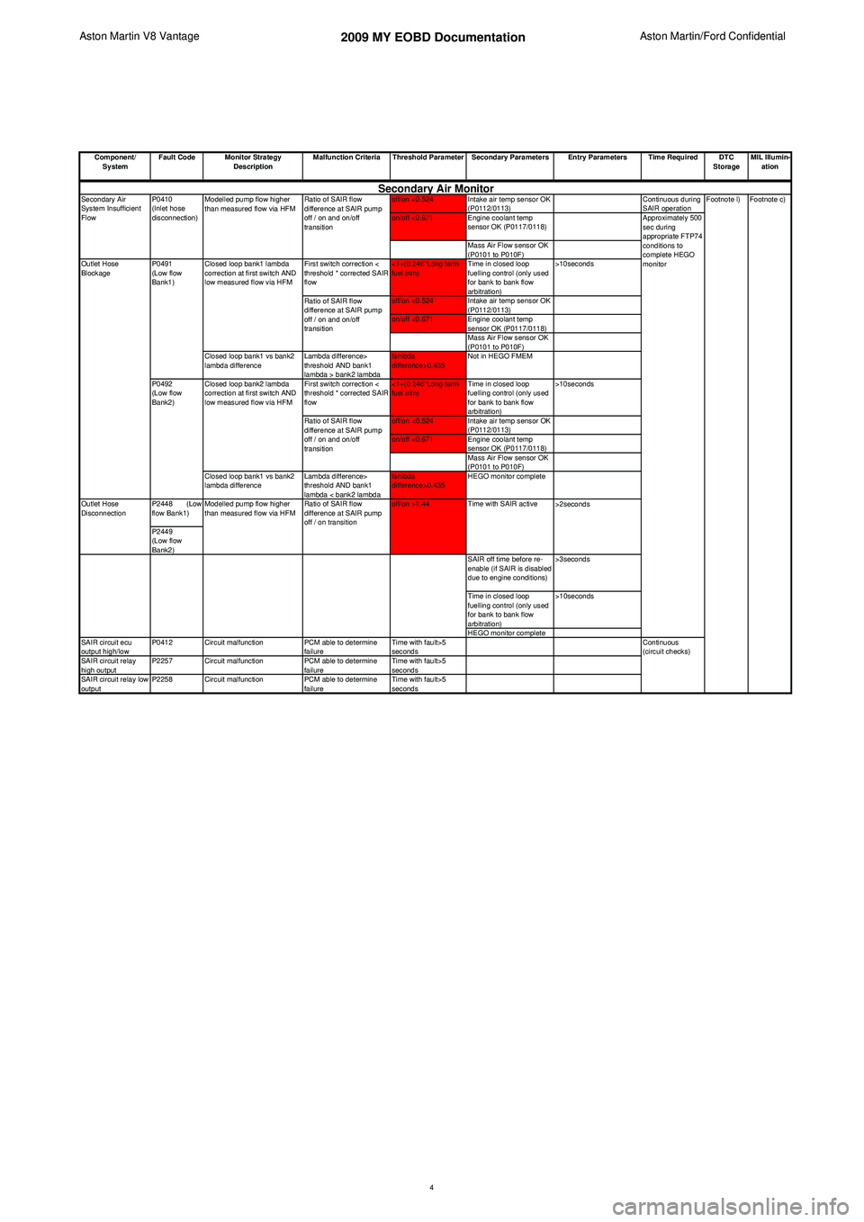
Component/ System Fault Code Monitor Strategy
Description Malfunction Criteria Threshold Parameter Secondary Parameters Entry Parameters Time Required DTC
StorageMIL Illumin-
ation
off/on <0.524 Intake air temp sensor OK (P0112/0113) Continuous during
SAIR operation
on/off <0.671 Engine coolant temp sensor OK (P0117/0118)
Mass Air Flow sensor OK
(P0101 to P010F)
First switch correction <
threshold * corrected SAIR
flow <1+(0.246*Long term
fuel trim)
Time in closed loop
fuelling control (only used
for bank to bank flow
arbitration) >10seconds
off/on <0.524 Intake air temp sensor OK (P0112/0113)
on/off <0.671 Engine coolant temp sensor OK (P0117/0118)
Mass Air Flow sensor OK
(P0101 to P010F)
Closed loop bank1 vs bank2
lambda difference Lambda difference>
threshold AND bank1
lambda > bank2 lambdalambda
difference>0.435
Not in HEGO FMEM
First switch correction <
threshold * corrected SAIR
flow <1+(0.246*Long term
fuel trim)
Time in closed loop
fuelling control (only used
for bank to bank flow
arbitration) >10seconds
off/on <0.524 Intake air temp sensor OK (P0112/0113)
on/off <0.671 Engine coolant temp sensor OK (P0117/0118)
Mass Air Flow sensor OK
(P0101 to P010F)
Closed loop bank1 vs bank2
lambda difference Lambda difference>
threshold AND bank1
lambda < bank2 lambdalambda
difference>0.435
HEGO monitor complete
P2448 (Low
flow Bank1)
P2449
(Low flow
Bank2) SAIR off time before re-
enable (if SAIR is disabled
due to engine conditions)>3seconds
Time in closed loop
fuelling control (only used
for bank to bank flow
arbitration) >10seconds
HEGO monitor complete
SAIR circuit ecu
output high/low P0412 Circuit malfunction
PCM able to determine
failure Time with fault>5
seconds
SAIR circuit relay
high output P2257 Circuit malfunction
PCM able to determine
failure Time with fault>5
seconds
SAIR circuit relay low
output P2258 Circuit malfunction
PCM able to determine
failure Time with fault>5
seconds
Ratio of SAIR flow
difference at SAIR pump
off / on and on/off
transition
Modelled pump flow higher
than measured flow via HFM
Ratio of SAIR flow
difference at SAIR pump
off / on and on/off
transition
Ratio of SAIR flow
difference at SAIR pump
off / on and on/off
transition
>2secondsFootnote c)
Approximately 500
sec during
appropriate FTP74
conditions to
complete HEGO
monitorSecondary Air Monitor
Modelled pump flow higher
than measured flow via HFM Ratio of SAIR flow
difference at SAIR pump
off / on transitionoff/on >1.44
Outlet Hose
Disconnection Footnote l)
Continuous
(circuit checks)
Outlet Hose
Blockage
P0492
(Low flow
Bank2)
P0410
(Inlet hose
disconnection)
Secondary Air
System Insufficient
Flow
Closed loop bank1 lambda
correction at first switch AND
low measured flow via HFM
Closed loop bank2 lambda
correction at first switch AND
low measured flow via HFM
P0491
(Low flow
Bank1)
Time with SAIR active
4
Page 899 of 947
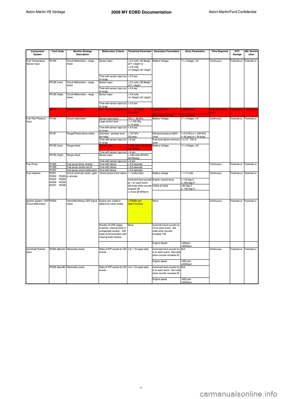
Aston Martin V8 Vantage 2009 MY EOBD DocumentationAston Martin/Ford Confidential
Component/ System Fault Code Monitor Strategy
Description Malfunction Criteria Threshold Parameter Secondary Parameters Entry Parameters Time Required DTC
StorageMIL Illumin-
ation
Sensor input < 0.2 volts 132.8degC
(271.1degF) or
> 4.9 volts
-41.2degC(-42.1degF)
Time with sensor input out
of range > 5.0 sec
Sensor input < 0.2 volts 132.8degC
(271.1degF)
Time with sensor input out
of range > 5.0 sec
Sensor input > 4.9 volts
-41.2degC(-42.1degF)
Time with sensor input out
of range > 5.0 sec
Engine off time >360minutes
ECU power up timer >0.1seconds
Sensor input stuck 103 +/- 59 kPa
Large control error > +/-103 kPa (> 15 psig)
Time with sensor input out
of range > 8.0 sec
(Demand - sensed) error
too large > 137 kPa
(20 psig)Demand pressure within
limits < 413 kPa or > 344 kPa
(< 60 psig or > 50 psig)
Time with sensor input out
of range > 8 sec
Fuel level above minimum
level > 0.15 * 100 %
Sensor input < 0.95 volts 174.23kPa
(25.33psig)
Time with sensor input out > 8 sec
Sensor input > 4.88 volts 647kPa
(93.95psig)
Time with sensor input out > 8 sec
P1233 Fuel pump driver module Time with failure > 5.0 seconds
P1235 Fuel pump control out of Time with failure > 5.0 seconds
P1237 Fuel pump circuit malfunction Time with failure > 5.0 seconds 1 = malfunction Battery voltage> 11.0 volts
Engine coolant temp < 116 deg C (< 240 deg F)
Intake air temp <66 deg C
(< 150 deg F)
Engine rpm (Used to
determine crank mode) > FN384 rpm
(See Function)None
Number of CKP edges
incorrect, missing tooth in
unexpected location. SW
loses synchronization with
missing tooth location None
Increment fault counter by
10 on each event. Set
code when counter
exceeds 100
Engine Speed >550rpm
<5000rpm
Increment fault counter by
2 on each event. Set code
when counter exceeds 50 N/A
Engine speed >550 rpm
<2200rpm
Increment fault counter by
2 on each event. Set code
when counter exceeds 50 N/A
Engine speed >550 rpm
<2200rpm Footnote a) Footnote c)
Continuous
<> +/-12.3degC
(54.1degF) Once per driving
cycle
Fuel Temperature
Sensor Input
ECT-Fuel rail temperature
Circuit Malfunction - range
check
Circuit Malfunction - range
check
Circuit Malfunction - range
check
P0180
P0182 (Low)
P0181 Rationality check
P0183 (High)
Ignition System- CKP
Circuit Malfunction P0320 Intermittent/Noisy CKP signal
check Footnote c)
Footnote c)
Ratio of PIP events to CID
events Continuous Footnote a) Footnote c)
n to 1 (To pass test)
n to 1 (To pass test)
Increment fault counter
by 1 on each event.
Set code when counter
exceeds 40
(> 8 sec @ 600rpm)
Smart power driver status
P0340 (BankA)
P0345 (BankB) Circuit continuity check, open
or shorted
P0201
P0202 P0203
P0203 P0204
P0205 P0206
P0207 P0208
Camshaft Position
Input Rationality check
Rationality checkRatio of PIP events to CID
events Continuous
Footnote a)
Footnote c)
Continuous Footnote a) Footnote c) Footnote a)
Battery Voltage 11< Voltage <18
11< Voltage <18 Continuous Footnote a) Footnote c)
11< Voltage <18
Circuit malfunction
Battery Voltage
Battery Voltage
Range check
Continuous Footnote a)
Fuel Injectors
Fuel Rail Pressure
Input
P0190
P0191
P0192 (Low)
P0193 (High)
Fuel Pump Range check
Range/Performance check
11
Page 923 of 947
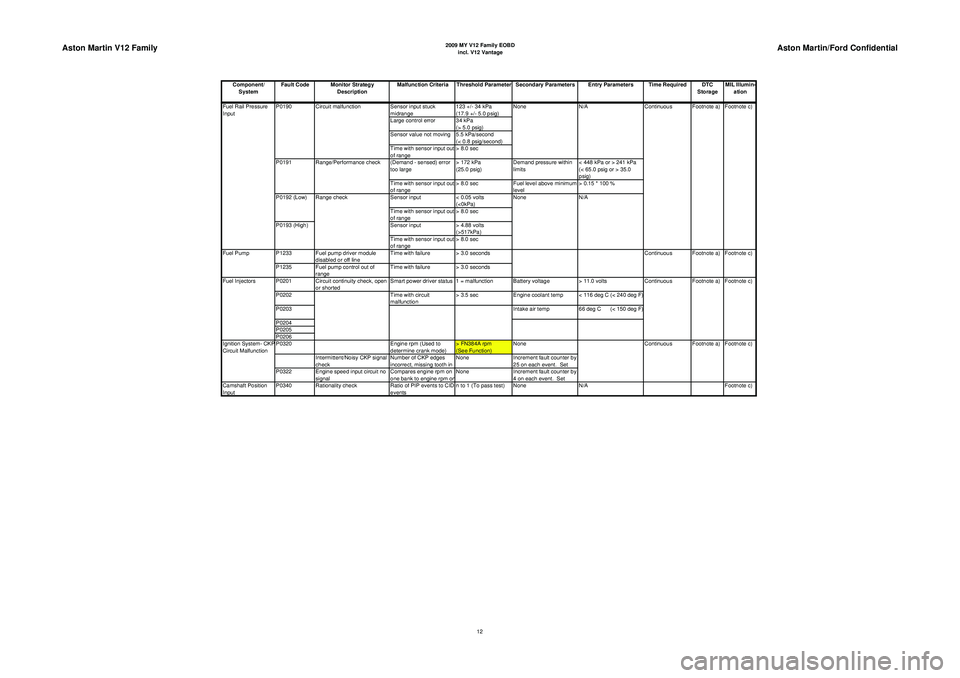
Aston Martin V12 Family
2009 MY V12 Family EOBDincl. V12 Vantage
Aston Martin/Ford Confidential
Component/ System Fault Code Monitor Strategy
Description Malfunction Criteria Threshold Parameter Secondary Parameters Entry Parameters Time Required DTC
StorageMIL Illumin-
ation
Sensor input stuck
midrange 123 +/- 34 kPa
(17.9 +/- 5.0 psig)
Large control error 34 kPa (> 5.0 psig)
Sensor value not moving 5.5 kPa/second (< 0.8 psig/second)
Time with sensor input out
of range > 8.0 sec
(Demand - sensed) error
too large > 172 kPa
(25.0 psig)Demand pressure within
limits < 448 kPa or > 241 kPa
(< 65.0 psig or > 35.0
psig)
Time with sensor input out
of range > 8.0 sec
Fuel level above minimum
level > 0.15 * 100 %
Sensor input < 0.05 volts
(<0kPa)
Time with sensor input out
of range > 8.0 sec
Sensor input > 4.88 volts
(>517kPa)
Time with sensor input out
of range > 8.0 sec
P1233 Fuel pump driver module disabled or off line Time with failure > 3.0 seconds
P1235 Fuel pump control out of range Time with failure > 3.0 seconds
P0201 Circuit continuity check, open or shorted Smart power driver status 1 = malfunction Battery voltage
> 11.0 volts
P0202 Time with circuit
malfunction > 3.5 sec
Engine coolant temp < 116 deg C (< 240 deg F)
P0203 Intake air temp66 deg C (< 150 deg F)
P0204
P0205
P0206
P0320 Engine rpm (Used to
determine crank mode) > FN384A rpm
(See Function)None
Intermittent/Noisy CKP signal
check Number of CKP edges
incorrect, missing tooth in None
Increment fault counter by
25 on each event. Set
P0322 Engine speed input circuit no signal Compares engine rpm on
one bank to engine rpm o
nNone
Increment fault counter by
4 on each event. Set
Camshaft Position
Input P0340 Rationality check
Ratio of PIP events to CID
events n to 1 (To pass test) None
N/A Footnote c)
Footnote c)
Fuel Rail Pressure
Input P0190
P0191
P0192 (Low)
P0193 (High)Range check
Range/Performance check
Fuel Pump Continuous
Circuit malfunction N/A
Continuous Footnote a) Footnote c)
None
None
N/A Footnote a)
Fuel Injectors Footnote c)
Ignition System- CKP
Circuit Malfunction Continuous Footnote a) Footnote c)
Continuous Footnote a)
12