load capacity ASTON MARTIN V8 VANTAGE 2010 Workshop Manual
[x] Cancel search | Manufacturer: ASTON MARTIN, Model Year: 2010, Model line: V8 VANTAGE, Model: ASTON MARTIN V8 VANTAGE 2010Pages: 947, PDF Size: 43.21 MB
Page 9 of 947

Lifting and Jacking
Issue 5, January 2010 Workshop Manual 0-0-9
Lifting and Jacking
Safety
•Recommended procedures for lifting, jacking and
towing must be strictly ob served to ensure personal
safety.
• Always use a vehicle hoist, ramp or pit for working
beneath the vehicle in preference to jacking.
• Never rely on a jack to supp ort a car independently, use
axle stands or blocks carefu lly placed at jacking points
to provide rigid support.
• When working beneath a vehicle, chock wheels as well
as applying handbrake.
• Ensure vehicle is standing on firm, level ground before
jacking or lifting.
• Check lifting equipment has adequate capacity for load
being lifted and is in full working order.
Jacking Points
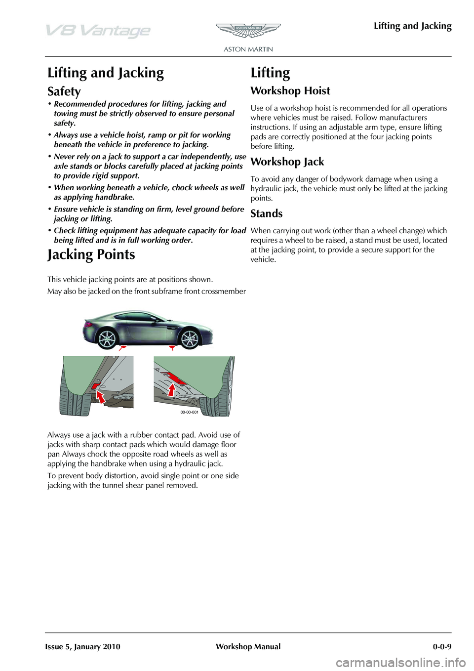
This vehicle jacking points are at positions shown.
May also be jacked on the front subframe front crossmember
Always use a jack with a rubber contact pad. Avoid use of
jacks with sharp contact pads which would damage floor
pan Always chock the opposite road wheels as well as
applying the handbrake when using a hydraulic jack.
To prevent body distortion, av oid single point or one side
jacking with the tunnel shear panel removed.
Lifting
Workshop Hoist
Use of a workshop hoist is recommended for all operations
where vehicles must be raised. Follow manufacturers
instructions. If using an adjustable arm type, ensure lifting
pads are correctly positioned at the four jacking points
before lifting.
Workshop Jack
To avoid any danger of bodywork damage when using a
hydraulic jack, the vehicle must only be lifted at the jacking
points.
Stands
When carrying out work (other than a wheel change) which
requires a wheel to be raised, a stand must be used, located
at the jacking point, to provide a secure support for the
vehicle.
00-00-001
Page 453 of 947

Road Wheels and Tyres (04.04)
Suspension (04.00)
May 2007 Workshop Manual 4-4-3
Maintenance
Factory installed tyres and road wheels are designed to
operate satisfactory when inflated to the recommended
inflation pressures (Refer to ’Inspection and Verification’,
page 4-4-4). The recommended pressures apply to vehicle
loads up to and including the full-rated load capacity.
Correct tyre pressures and driving technique have an
important influence on tyre life. Heavy cornering,
excessively rapid acceleration and unnecessary sharp
braking increase tyre wear.
Replacement tyres should follow the recommended:
The use of any other size or type may seriously affect:
Wheels need to be renewed when:
Safety
Tyre Replacement and Wheel
Interchanging
When replacement of tyres is required it is preferable to
install a complete vehicle set. S hould either the front or rear
tyres only show excessive wear, new tyres must be installed
to replace worn ones. Under no circumstances interchange
tyres from side to side, front to re ar or vice versa as individual
tyre wear produces unique characteristics depending upon
their position. If the position is changed after wear has
occurred, the performance of the tyre will be adversely
affected.
New tyres must be balanced before installing to the vehicle.
•Size
•Speed rating
•Load range
• Radial construction type
•Safety
•Ride
•Handling
• Speedometer and Odometer calibration • Vehicle ground clearance
• Tyre clearance between
body and chassis
• Wheel bearing life
• Brake cooling
• Impact damaged
• Heavily corroded
• Porous • Wheel stud holes or seats
become damaged
• They have excessive radial or lateral runout.
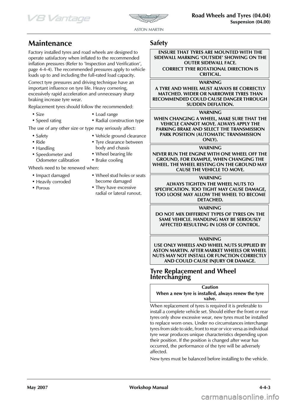
ENSURE THAT TYRES ARE MOUNTED WITH THE
SIDEWALL MARKING ‘OUTSIDE’ SHOWING ON THE
OUTER SIDEWALL FACE.
CORRECT TYRE ROTATIONAL DIRECTION IS CRITICAL.
WA R N I N G
A TYRE AND WHEEL MUST ALWAYS BE CORRECTLY MATCHED. WIDER OR NARROWER TYRES THAN
RECOMMENDED COULD CAUSE DANGER THROUGH
SUDDEN DEFLATION.
WA R N I N G
WHEN CHANGING A WHEEL, MAKE SURE THAT THE VEHICLE CANNOT MOVE. ALWAYS APPLY THE
PARKING BRAKE AND SELE CT THE TRANSMISSION
PARK POSITION (AUTOMATIC TRANSMISSION ONLY).
WA R N I N G
NEVER RUN THE ENGINE WITH ONE WHEEL OFF THE GROUND, FOR EXAMPLE, WHEN CHANGING THE
WHEEL. THE WHEEL RESTING ON THE GROUND MAY CAUSE THE VEHICLE TO MOVE.
WA R N I N G
ALWAYS TIGHTEN THE WHEEL NUTS TO
SPECIFICATION. TOO TIGHT MAY CAUSE DAMAGE,
TOO LOOSE MAY ALLOW TH E WHEEL TO BECOME
DETACHED.
WAR NI NG
DO NOT MIX DIFFERENT TY PES OF TYRES ON THE
SAME VEHICLE. HANDLING MAY BE SERIOUSLY AFFECTED RESULTING IN LOSS OF CONTROL.
WAR NI NG
USE ONLY WHEELS AND WHEEL NUTS SUPPLIED BY
ASTON MARTIN. AFTER MARKET WHEELS OR WHEEL
NUTS MAY NOT INSTALL OR FUNCTION CORRECTLY
AND COULD CAUSE INJURY OR DAMAGE.
Caution
When a new tyre is installe d, always renew the tyre
valve.
Page 889 of 947

Aston Martin V8 Vantage 2009 MY EOBD DocumentationAston Martin/Ford Confidential
Component/ System Fault Code Monitor Strategy
Description Malfunction Criteria Threshold Parameter Secondary Parameters Entry Parameters Time Required DTC
StorageMIL Illumin-
ation
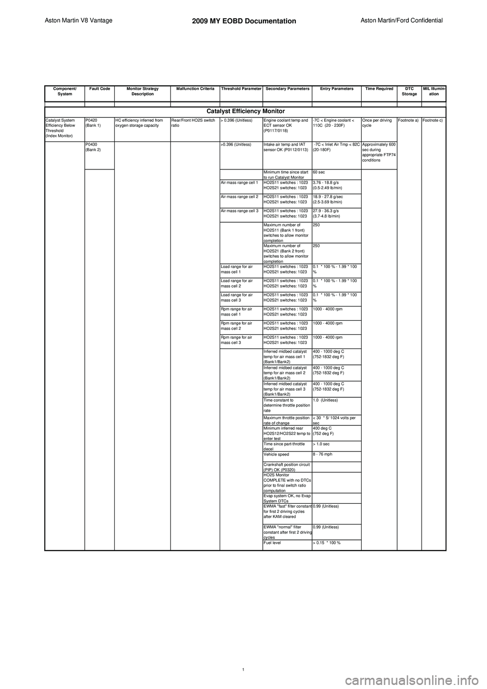
Catalyst System
Efficiency Below
Threshold
(Index Monitor) P0420
(Bank 1)
HC efficiency inferred from
oxygen storage capacity Rear/Front HO2S switch
ratio> 0.396 (Unitless) Engine coolant temp and
ECT sensor OK
(P0117/0118) -7C < Engine coolant <
110C (20 - 230F)
Once per driving
cycle
P0430
(Bank 2) >0.396 (Unitless) Intake air temp and IAT
sensor OK (P0112/0113) -7C < Inlet Air Tmp < 82C
(20-180F) Approximately 600
sec during
appropriate FTP74
conditions
Minimum time since start
to run Catalyst Monitor 60 sec
Air mass range cell 1 HO2S11 switches : 1023 HO2S21 switches: 1023 3.76 - 18.8 g/s
(0.5-2.49 lb/min)
Air mass range cell 2 HO2S11 switches : 1023 HO2S21 switches: 1023 18.9 - 27.8 g/sec
(2.5-3.69 lb/min)
Air mass range cell 3 HO2S11 switches : 1023 HO2S21 switches: 1023 27.9 - 36.3 g/s
(3.7-4.8 lb/min)
Maximum number of
HO2S11 (Bank 1 front)
switches to allow monitor
completion 250
Maximum number of
HO2S21 (Bank 2 front)
switches to allow monitor
completion 250
Load range for air
mass cell 1 HO2S11 switches : 1023
HO2S21 switches: 1023 0.1 * 100 % - 1.99 * 100
%
Load range for air
mass cell 2 HO2S11 switches : 1023
HO2S21 switches: 1023 0.1 * 100 % - 1.99 * 100
%
Load range for air
mass cell 3 HO2S11 switches : 1023
HO2S21 switches: 1023 0.1 * 100 % - 1.99 * 100
%
Rpm range for air
mass cell 1 HO2S11 switches : 1023
HO2S21 switches: 1023 1000 - 4000 rpm
Rpm range for air
mass cell 2 HO2S11 switches : 1023
HO2S21 switches: 1023 1000 - 4000 rpm
Rpm range for air
mass cell 3 HO2S11 switches : 1023
HO2S21 switches: 1023 1000 - 4000 rpm
Inferred midbed catalyst
temp for air mass cell 1
(Bank1/Bank2) 400 - 1000 deg C
(752-1832 deg F)
Inferred midbed catalyst
temp for air mass cell 2
(Bank1/Bank2) 400 - 1000 deg C
(752-1832 deg F)
Inferred midbed catalyst
temp for air mass cell 3
(Bank1/Bank2) 400 - 1000 deg C
(752-1832 deg F)
Time constant to
determine throttle position
rate 1.0 (Unitless)
Maximum throttle position
rate of change < 30 * 5/ 1024 volts per
sec
Minimum inferred rear
HO2S12/HO2S22 temp to
enter test 400 deg C
(752 deg F)
Time since part-throttle
decel > 1.0 sec
Vehicle speed 8 - 76 mph
Crankshaft position circuit
(PIP) OK (P0320)
HO2S Monitor
COMPLETE with no DTCs
prior to final switch ratio
computation
Evap system OK, no Evap
System DTCs
EWMA "fast" filter constant
for first 2 driving cycles
after KAM cleared 0.99 (Unitless)
EWMA "normal" filter
constant after first 2 driving
cycles 0.99 (Unitless)
Fuel level > 0.15 * 100 % Footnote a)
Footnote c)
Catalyst Efficiency Monitor
1
Page 900 of 947

Aston Martin V8 Vantage 2009 MY EOBD DocumentationAston Martin/Ford Confidential
Component/ System Fault Code Monitor Strategy
Description Malfunction Criteria Threshold Parameter Secondary Parameters Entry Parameters Time Required DTC
StorageMIL Illumin-
ation
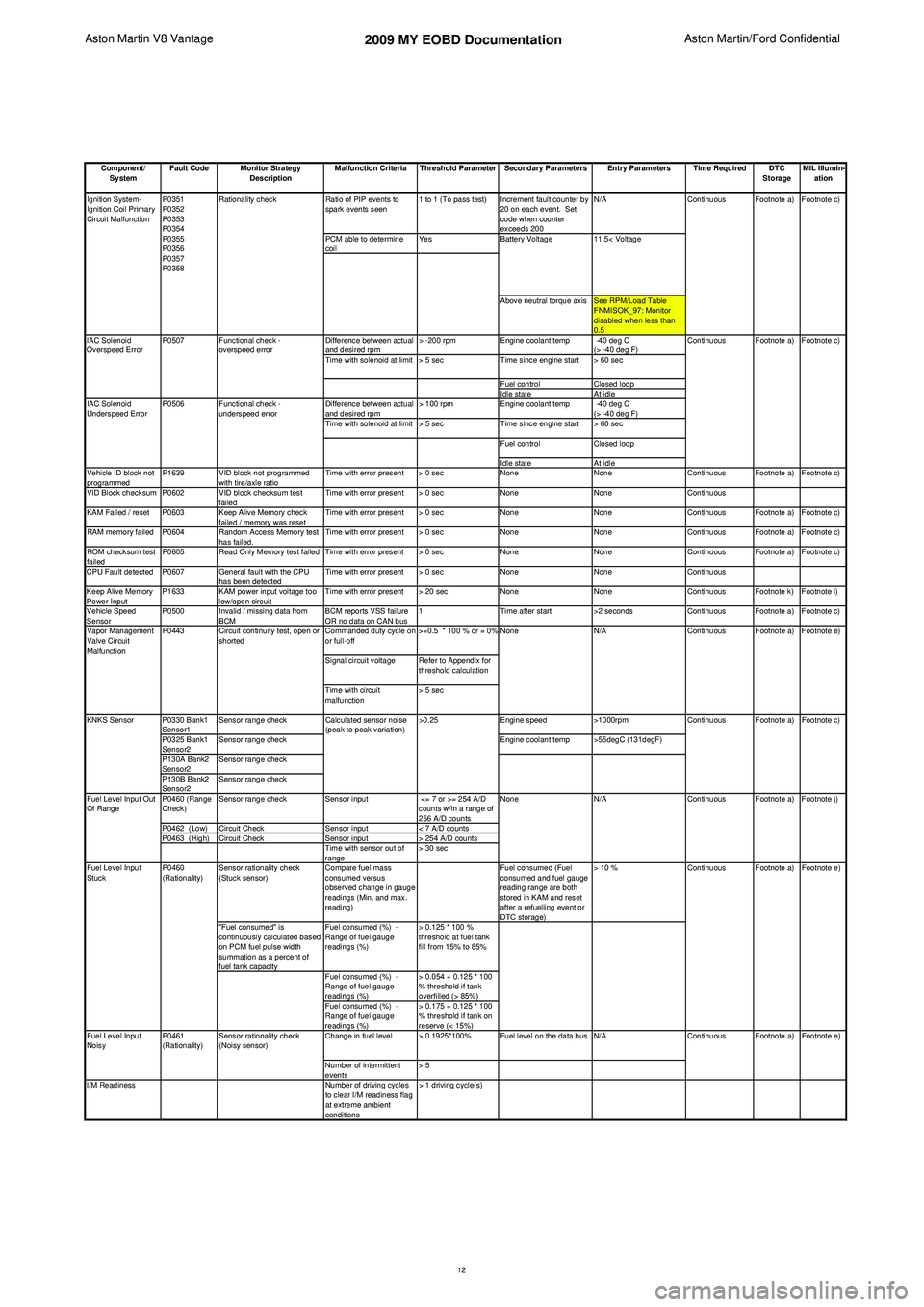
Ratio of PIP events to
spark events seen 1 to 1 (To pass test) Increment fault counter by
20 on each event. Set
code when counter
exceeds 200 N/A
PCM able to determine
coil Yes
Above neutral torque axis See RPM/Load Table FNMISOK_97: Monitor
disabled when less than
0.5
Difference between actual
and desired rpm > -200 rpm
Engine coolant temp -40 deg C
(> -40 deg F)
Time with solenoid at limit > 5 sec Time since engine start > 60 sec
Fuel control Closed loop
Idle state At idle
Difference between actual
and desired rpm > 100 rpm
Engine coolant temp -40 deg C
(> -40 deg F)
Time with solenoid at limit > 5 sec Time since engine start > 60 sec
Fuel control Closed loop
Idle state At idle
Vehicle ID block not
programmed P1639 VID block not programmed
with tire/axle ratio Time with error present > 0 sec
NoneNoneContinuous Footnote a) Footnote c)
VID Block checksum P0602 VID block checksum test failedTime with error present > 0 sec
NoneNoneContinuous
KAM Failed / reset P0603 Keep Alive Memory check failed / memory was resetTime with error present > 0 sec
NoneNoneContinuous Footnote a) Footnote c)
RAM memory failed P0604 Random Access Memory test has failed.Time with error present > 0 sec
NoneNoneContinuous Footnote a) Footnote c)
ROM checksum test
failed P0605 Read Only Memory test failed Time with error present > 0 sec
NoneNoneContinuous Footnote a) Footnote c)
CPU Fault detected P0607 General fault with the CPU has been detectedTime with error present > 0 sec
NoneNoneContinuous
Keep Alive Memory
Power Input P1633 KAM power input voltage too
low/open circuit Time with error present > 20 sec
NoneNoneContinuous Footnote k) Footnote i)
Vehicle Speed
Sensor P0500 Invalid / missing data from
BCM BCM reports VSS failure
OR no data on CAN bus1
Time after start >2 secondsContinuous Footnote a) Footnote c)
Commanded duty cycle on
or full-off >=0.5 * 100 % or = 0%
Signal circuit voltage Refer to Appendix for threshold calculation
Time with circuit
malfunction > 5 sec
P0330 Bank1
Sensor1 Sensor range check
Engine speed>1000rpm
P0325 Bank1
Sensor2 Sensor range check
Engine coolant temp >55degC (131degF)
P130A Bank2
Sensor2 Sensor range check
P130B Bank2
Sensor2 Sensor range check
P0460 (Range
Check) Sensor range check
Sensor input <= 7 or >= 254 A/D
counts w/in a range of
256 A/D counts
P0462 (Low) Circuit Check Sensor input< 7 A/D counts
P0463 (High) Circuit Check Sensor input> 254 A/D counts
Time with sensor out of
range > 30 sec
Sensor rationality check
(Stuck sensor) Compare fuel mass
consumed versus
observed change in gauge
readings (Min. and max.
reading) Fuel consumed (Fuel
consumed and fuel gauge
reading range are both
stored in KAM and reset
after a refuelling event or
DTC storage)> 10 %
"Fuel consumed" is
continuously calculated based
on PCM fuel pulse width
summation as a percent of
fuel tank capacity Fuel consumed (%) -
Range of fuel gauge
readings (%)
> 0.125 * 100 %
threshold at fuel tank
fill from 15% to 85%
Fuel consumed (%) -
Range of fuel gauge
readings (%) > 0.054 + 0.125 * 100
% threshold if tank
overfilled (> 85%)
Fuel consumed (%) -
Range of fuel gauge
readings (%) > 0.175 + 0.125 * 100
% threshold if tank on
reserve (< 15%)
Change in fuel level > 0.1925*100% Fuel level on the data bus N/A
Number of intermittent
events > 5
I/M Readiness Number of driving cycles
to clear I/M readiness flag
at extreme ambient
conditions > 1 driving cycle(s) Footnote e)
Footnote a)
Footnote c)
Footnote a) Footnote j) Footnote e)
Fuel Level Input
Noisy Continuous Footnote a)
Continuous Footnote a)
P0461
(Rationality) Sensor rationality check
(Noisy sensor)
Fuel Level Input
Stuck
P0460
(Rationality) Continuous
N/A Continuous
Calculated sensor noise
(peak to peak variation)
>0.25
KNKS Sensor
Fuel Level Input Out
Of Range NoneFootnote a) Footnote e)
Vapor Management
Valve Circuit
Malfunction P0443 Circuit continuity test, open or
shorted None
N/A Continuous
11.5< Voltage
Ignition System-
Ignition Coil Primary
Circuit Malfunction
IAC Solenoid
Underspeed Error P0507
P0506
Functional check -
overspeed error
Functional check -
underspeed error
IAC Solenoid
Overspeed Error
Footnote a) Footnote c)
Continuous
P0351
P0352
P0353
P0354
P0355
P0356
P0357
P0358
Rationality check
Continuous Footnote a) Footnote c)
Battery Voltage
12
Page 912 of 947

Aston Martin V12 Family
2009 MY V12 Family EOBDincl. V12 Vantage
Aston Martin/Ford Confidential
Component/ System Fault Code Monitor Strategy
Description Malfunction Criteria Threshold Parameter Secondary Parameters Entry Parameters Time Required DTC
StorageMIL Illumin-
ation
P0420
(Bank 1) HC efficiency inferred from
oxygen storage capacity Rear/Front HO2S switch
ratio> 0.76 (Unitless) Engine coolant temp and
ECT sensor OK
(P0117/0118) 65C < Engine coolant
< 110C (150 - 230F)
Once per driving
cycleFootnote a) Footnote c)
P0430
(Bank 2) HC efficiency inferred from
oxygen storage capacity Rear/Front HO2S switch
ratio>0.76 (Unitless) Intake air temp and IAT
sensor OK (P0112/0113) -7C < Inlet Air Tmp
< 82C (20-180F) Approximately 900
sec
Minimum time since start
to run Catalyst Monitor 60 sec
Air mass range cell 1 HO2S11 switches : 200 HO2S21 switches: 200 3.78 - 11.3 g/s
(0.5-1.5 lb/min)
Air mass range cell 2 HO2S11 switches : 200 HO2S21 switches: 200 11.3 - 18.9 g/sec
(1.5-2.5 lb/min)
Air mass range cell 3 HO2S11 switches : 200 HO2S21 switches:
FEGO2_MX_CT3 18.9 - 26.5 g/s
(2.5-3.5 lb/min)
Maximum number of
HO2S11 (Bank 1 front)
switches to allow monitor
completion 300
Maximum number of
HO2S21 (Bank 2 front)
switches to allow monitor
completion 300
Load range for air
mass cell 1 HO2S11 switches : 200
HO2S21 switches: 200 0.1 * 100 % - 1.0 * 100 %
Load range for air
mass cell 2 HO2S11 switches : 200
HO2S21 switches: 200 0.1 * 100 % - 1.0 * 100 %
Load range for air
mass cell 3 HO2S11 switches : 200
HO2S21 switches: 200 0.1 * 100 % - 1.0 * 100 %
Rpm range for air
mass cell 1 HO2S11 switches : 200
HO2S21 switches: 200 0 - 4000 rpmCatalyst Efficiency MonitorCatalyst System
Efficiency Below
Threshold
(Index Monitor)
1