ECU ASTON MARTIN V8 VANTAGE 2010 Workshop Manual
[x] Cancel search | Manufacturer: ASTON MARTIN, Model Year: 2010, Model line: V8 VANTAGE, Model: ASTON MARTIN V8 VANTAGE 2010Pages: 947, PDF Size: 43.21 MB
Page 731 of 947
Vehicle Control System (18.08)
Electric Distribution/Electronic Control (18.00)
18-2-2 Workshop Manual May 2007
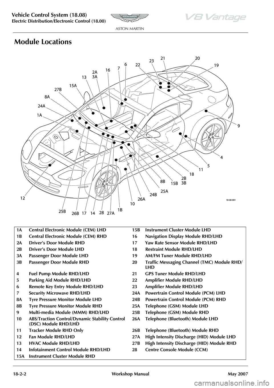
Module Locations
1A Central Electronic Module (CEM) LH D15BInstrument Cluster Module LHD
1B Central Electronic Module (CEM) RH D 16 Navigation Display Module RHD/LHD
2A Driver’s Door Module RHD 17 Yaw Rate Sensor Module RHD/LHD
2B Driver’s Door Module LHD 1 8Restraint Module RHD/LHD
3A Passenger Door Module LHD 19 AM/FM Tuner Module RHD/LHD
3B Passenger Door Module RHD 20 Traffic Messaging Channel (TMC) Module RHD/
LHD
4 Fuel Pump Module RHD/LHD 21 GPS Tuner Module RHD/LHD
5 Parking Aid Module RHD/LHD 22 Amplifier Module RHD/LHD
6 Remote Key Entry Module RHD/LH D23Amplifier Module RHD/LHD
7 Security Microwave RHD/LHD 24A Powe rtrain Control Module (PCM) LHD
8A Tyre Pressure Monitor Module LHD 24B Powertrain Control Module (PCM) RHD
8B Tyre Pressure Monitor Module RHD 25A Telephone (GSM) Module LHD
9Multi-media Module (MMM) RHD/LHD 25B Teleph one (GSM) Module RHD
10 ABS/Traction Control/Dy namic Stability Control
(DSC) Module RHD/LHD 26A Telephone (Bluetooth) Module LHD
11 Tracker Module RHD Only 26B Tel ephone (Bluetooth) Module RHD
12 Fan Module RHD/LHD 27A High Intensity Discharge (HID) Module LHD
13 HVAC Module RHD/LHD 27B High Intensity Discharge (HID) Module RHD
14 Infotainment Control Module RHD/ LHD 28 Centre Console Module (CCM)
15A Instrument Cluster Module RHD
Page 732 of 947
Issue 5, Janua
ry 2010 Workshop Manual 19-1-1
Electronic Features (19.00)
Contents
Active Anti-Theft System (19.01) ......................... 19-1-2
Alarm System Overview ......................................... 1-2Component Descriptions ....................................... 1-2
Functional Description ........................................... 1-3 Overview – Alarm .................................................. 1-3
General setting ....................................................... 1-3
Door open ............................................................. 1-3
Disable the Alarm .................................................. 1-3
Reduced guard mode ............................................ 1-3
Alarm Cycle ........................................................... 1-3
Panic Alarm ........................................................... 1-3
Remote Transmitter................................................ 1-4 Key Learning Operations ........................................ 1-4
Integrated Passive Anti-Theft System (IPATS) ........ 1-4 Description ............................................................ 1-4
Disarming IPATS .................................................... 1-4
Arming IPATS......................................................... 1-4
IPATS LED ............................................................... 1-4 Key Programming................................................... 1-5
Maintenance ........................................................... 1-5 Tracker-Renew ...................................................... 1-5
Mass Movement Sensor-Renew.............................. 1-5
Pats Tranceiver ECU (Pre-08 MY Only)
- Remove and Install .............................................. 1-5
Hood Latch Switch-Renew..................................... 1-6
Alarm Siren Assembly - Remove and Install ............ 1-6
Electronic Features Modules (19.05) ................... 19-5-1 Maintenance ........................................................... 5-1Electronic Passenger Door Module-Renew ............. 5-1
Electronic Driver’s Door Module-Renew ................ 5-1
Page 735 of 947
Active Anti-Theft System (19.01)
Electronic Features (19.00)19-1-4 Workshop ManualIssue 5, January 2010
Remote Transmitter
The security system allows up to eight remote transmitters to
be used for controlling the system functions.
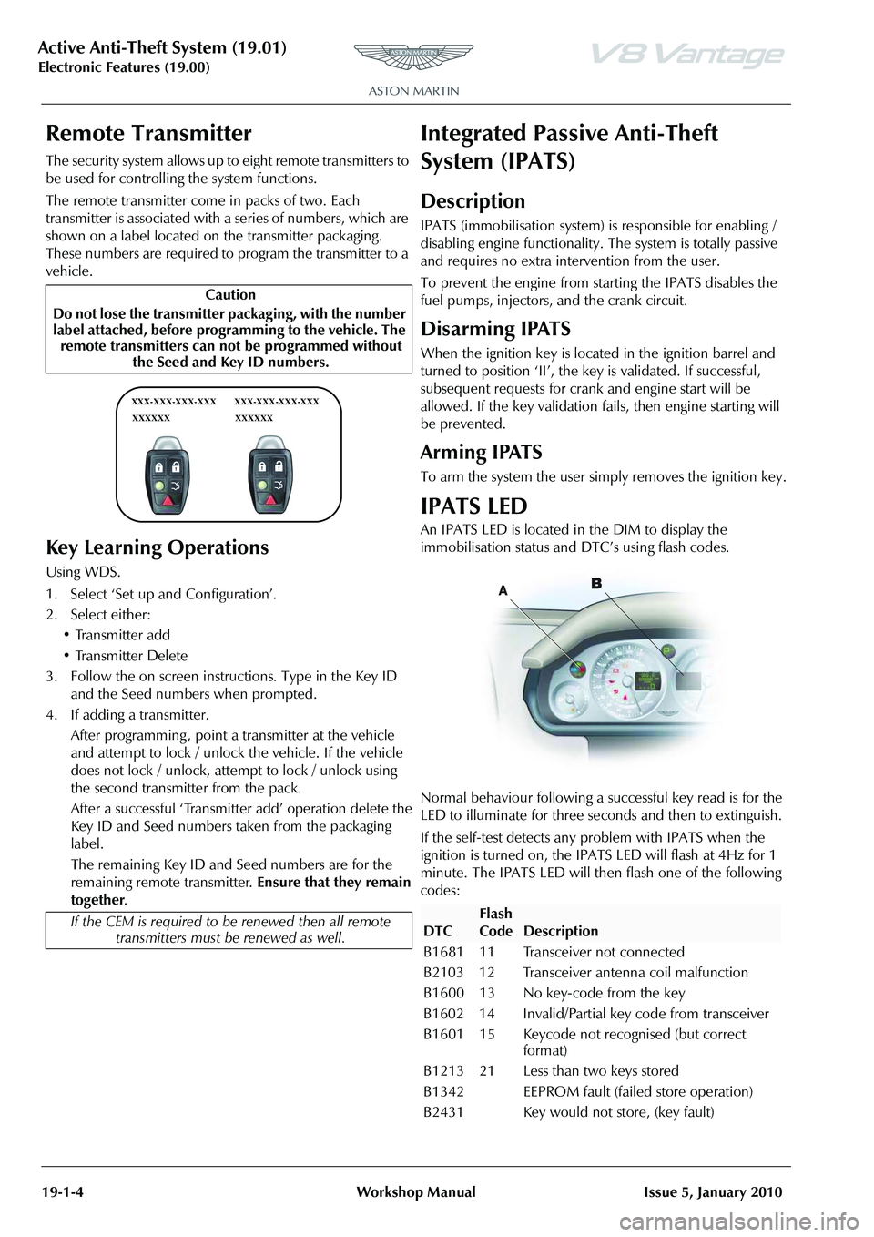
The remote transmitter come in packs of two. Each
transmitter is associated with a
series of numbers, which are
shown on a label located on the transmitter packaging.
These numbers are required to program the transmitter to a
vehicle.
Key Learning Operations
Using WDS.
1. Select ‘Set up and Configuration’.
2. Select either:
• Transmitter add
• Transmitter Delete
3. Follow the on screen instructions. Type in the Key ID and the Seed numbers when prompted.
4. If adding a transmitter. After programming , point a transmitter at the vehicle
and attempt to lock / unlock the vehicle. If the vehicle
does not lock / unlock, attempt to lock / unlock using
the second transmitter from the pack.
After a successful ‘Transmitter add’ operation delete the
Key ID and Seed numbers taken from the packaging
label.
The remaining Key ID and Seed numbers are for the
remaining remote transmitter. Ensure that they remain
together .
Integrated Passive Anti-Theft
System (IPATS)
Description
IPATS (immobilisation system) is responsible for enabling /
disabling engine functionality. The system is totally passive
and requires no extra inte rvention from the user.
To prevent the engine from starting the IPATS disables the
fuel pumps, injectors, and the crank circuit.
Disarming IPATS
When the ignition key is located in the ignition barrel and
turned to position ‘II’, the key is validated. If successful,
subsequent requests for crank and engine start will be
allowed. If the key validation fa ils, then engine starting will
be prevented.
Arming IPATS
To arm the system the user simply removes the ignition key.
IPATS LED
An IPATS LED is located in the DIM to display the
immobilisation status and DTC’s using flash codes.
Normal behaviour following a su ccessful key read is for the
LED to illuminate for three seconds and then to extinguish.
If the self-test detects any problem with IPATS when the
ignition is turned on, the IPAT S LED will flash at 4Hz for 1
minute. The IPATS LED will then flash one of the following
codes:
Caution
Do not lose the transmitter packaging, with the number
label attached, before progra mming to the vehicle. The
remote transmitters can not be programmed without the Seed and Key ID numbers.
If the CEM is required to be renewed then all remote
transmitters must be renewed as well.
XXX-XXX-XXX-XXX
XXXXXX XXX-XXX-XXX-XXX
XXXXXX
DTC
Flash
Code
Description
B1681 11 Transceiver not connected
B2103 12 Transceiver antenna coil malfunction
B1600 13 No key-code from the key
B1602 14 Invalid/Partial key code from transceiver
B1601 15 Keycode not recognised (but correct format)
B1213 21 Less than two keys stored
B1342 EEPROM fault (failed store operation)
B2431 Key would not store, (key fault)
Page 736 of 947
Active Anti-Theft System (19.01)
Electronic Features (19.00)
Issue 5, Jan
ua
ry 2010 Workshop Manual 19-1-5
Key Programming
All vehicle keys are required to perform key programming.
Using AMDS.
1. Insert the first key to the ignition.
2. Select ‘Set up and Configuration’ on AMDS.
3. Select either: •Key Learn
•Key Delete
4. Follow the on screen instructions. You will be prompted to program successiv e keys as required.
Count Keys
Using AMDS.
Select Count keys to check how many keys are programmed
into the vehicle security.
Maintenance
Tracker-Renew
Removal
1. Remove IP assembly (see Workshop Manual procedure
01.12.AB Instrument Panel - Facia Assembly - Remove
for Access and Refit).
2. Disconnect multiplugs (x2) from tracker horizon and
GPS antenna assembly.
3. Remove nuts (x2) securing tracker assembly to mounting bracket.
4. Release GPS antenna from bracket, remove tracker assembly.
5. Remove screws (x2) securing tracker horizon to bracket.
Intallation
1. Position tracker horizon to bracket, install and tighten screws (x2).
2. Install tracker horizon assenb ly, install and tighten nuts
(x2).
3. Install tracker GPS antenna in bracket.
4. Connect multiplugs (x2).
5. Install IP assembly (see Workshop Manual procedure 01.12.AB Instrument Panel - Facia Assembly - Remove
for Access and Refit).
Mass Movement Sensor-Renew
Removal
1. Remove front header console assembly (see Workshop Manual procedure 01.05.BC Console Assembly - Front
Header - Renew)
2. Remove RH front pillar upper trim panel (see Workshop Manual procedure 01.05.BD Trim - Upper Panel - Front
Pillar - RH - Renew).
3. Remove LH front pillar uppe r trim panel (see Workshop
Manual procedure 01.05.BE Trim - Upper Panel - Front
Pillar - LH - Renew).
4. Remove sun visors Allen screws (x4).
5. Remove sunvisors.
6. Remove screws (x2) front header to body.
7. Remove front header panel.
8. Remove mass movement sensor from front header.
Installation
1. Install mass movement sensor.
2. Install front header panel.
3. Position sun visors and install screws (x4).
4. Install RH front pillar uppe r trim panel (see Workshop
Manual procedure 01.05.BD Trim - Upper Panel - Front
Pillar - RH - Renew).
5. Install LH front pillar upper trim panel (see Workshop Manual procedure 01.05.BE Trim - Upper Panel - Front
Pillar - LH - Renew).
6. Install front header console assembly (see Workshop Manual procedure 01.05.BC Console Assembly - Front
Header - Renew).
Pats Tranceiver ECU (Pre-08 MY Only) -
Remove and Install
Removal
1. Remove the top and bottom shrouds for the steering column (Refer to ’Top and Bottom Shrouds for the
Steering Column - Remove and Install’, page 11-4-4).
2. Release the clips that attach the wiper switch to its mounting.
3. Release the wiper switch from its mounting.
4. Move the wiper switch away to give access.
5. Remove the self-tapping screw that attaches the PATS tranceiver ECU (ECU) to the steering column.
6. Disconnect the electrical connector for the ECU.
7. Remove the ECU.
Installation
1. Put the ECU in position on the steering column.
2. Install the self-tapping screw to attach the ECU.
3. Connect the electrical connector for the ECU.
4. Install the wiper switch in the mounting.
Note: You will need a
ccess to the Internet
Repair Operation Time (ROT)
Repair Operation Time (ROT)
Repair Operation Time (ROT)
Page 737 of 947

Active Anti-Theft System (19.01)
Electronic Features (19.00)19-1-6 Workshop ManualIssue 5, January 2010
5. Make sure that the clips that attach the switch are
correctly engaged.
6. Install the top and bottom steering column shrouds (Refer to ’Top and Bottom Shrouds for the Steering
Column - Remove and Install’, page 11-4-4).
Hood Latch Switch-Renew
Removal
1. Remove grille (see Workshop Manual procedure 01.08.AA Grille - Radiator - Renew).
2. Remove slam panel (bolts x12).
3. Remove bolts (x4) securing PAS oil cooler.
4. Remove bolts securing crossmember to inner wing (x4).
5. Remove bolts and spacers securing crossmember to wing (x2).
6. Move crossmember to one side and lift up clear of location (protect paintwork).
7 . D i s c o n n e c t b o n n e t l a t c h m u l t i p l u g .
8. Remove switch from latch body.
Installation
1. Install switch to latch body.
2. Connect bonnet latch multiplug.
3. Install crossmember (as removed).
4. Install bolts and spacers securing crossmember to wing (x2).
5. Install bolts securing crossmember to inner wing (x4).
6. Install bolts (x4) securing PAS oil cooler.
7. Install slam panel (bolts x12).
8. Install grille (see Workshop Manual procedure 01.08.AA
Grille - Radiator - Renew).
Alarm Siren Assembly - Remove and
Install
Removal
1. Remove the left rear wheel (refer to Workshop Manual procedure 04.04.EC).
2. Remove the four self-tapping screws and the scrivet that attach the rear of the left, rear wheelarch liner.
3. Move the wheelarch liner away to get access to the alarm siren assembly (siren).
4. Remove the the drain hose for the fuel filler from the clips.
5. Move the drain hose for the fuel filler away.
6. Remove the two M6 nuts that attach the siren to the mounting bracket. 7. Disconnect the electrical connector from the siren.
8. Remove the siren.
Installation
1. Connect the electrical connector to the siren.
2. Put the siren in position into the mounting bracket.
3. Install the two M6 nuts to attach the siren to the
mounitng bracket.
4. Install the drain hose for the fuel filler into the attachment clips,
5. Put the wheelarch liner into the fully installed position.
6. Install the four self-tapping screws and the scrivet that attach the wheelarch liner.
7. Install the left rear wheel(refer to Workshop Manual procedure 04.04.EC).
Repair Operation Time (ROT)
Repair Operation Time (ROT)
Page 738 of 947
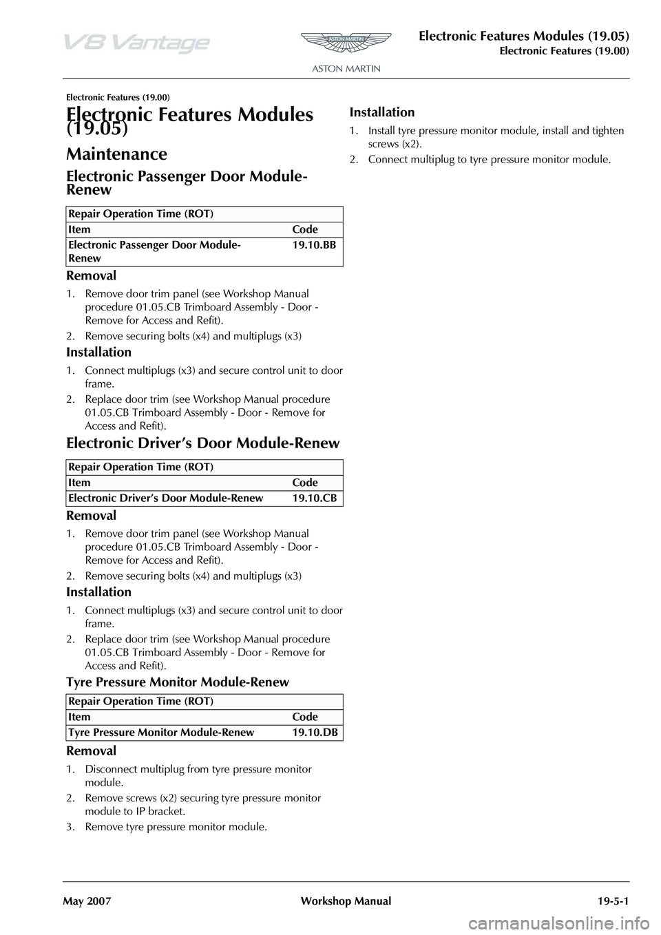
Electronic Features Modules (19.05)
Electronic Features (19.00)
May 2007 Workshop Manual 19-5-1
Electronic Features (19.00)
Electronic Features Modules
(19.05)
Maintenance
Electronic Passenger Door Module-
Renew
Removal
1. Remove door trim panel (see Workshop Manual
procedure 01.05.CB Trimboard Assembly - Door -
Remove for Access and Refit).
2. Remove securing bolts (x4) and multiplugs (x3)
Installation
1. Connect multiplugs (x3) and secure control unit to door frame.
2. Replace door trim (see Workshop Manual procedure 01.05.CB Trimboard Assembly - Door - Remove for
Access and Refit).
Electronic Driver’s Door Module-Renew
Removal
1. Remove door trim panel (see Workshop Manual procedure 01.05.CB Trimboard Assembly - Door -
Remove for Access and Refit).
2. Remove securing bolts (x4) and multiplugs (x3)
Installation
1. Connect multiplugs (x3) and secure control unit to door frame.
2. Replace door trim (see Workshop Manual procedure 01.05.CB Trimboard Assembly - Door - Remove for
Access and Refit).
Tyre Pressure Monitor Module-Renew
Removal
1. Disconnect multiplug from tyre pressure monitor module.
2. Remove screws (x2) securi ng tyre pressure monitor
module to IP bracket.
3. Remove tyre pressure monitor module.
Installation
1. Install tyre pressure monitor module, install and tighten screws (x2).
2. Connect multiplug to tyre pressure monitor module.
Repair Operation Time (ROT)
Repair Operation Time (ROT)
Repair Operation Time (ROT)
Page 752 of 947
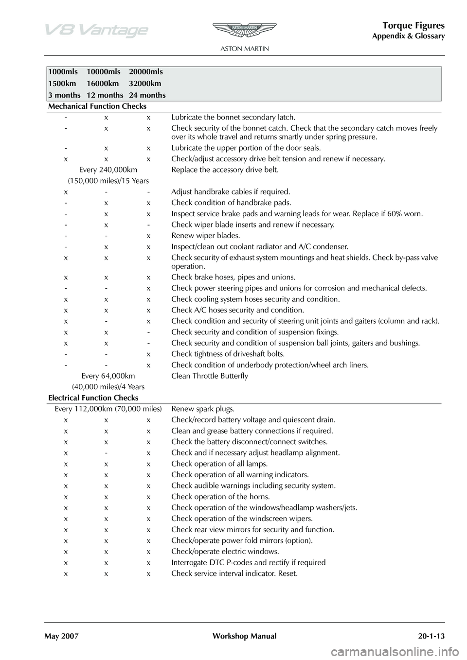
Torque Figures
Appendix & Glossary
May 2007 Workshop Manual 20-1-13
Mechanical Function Checks - x x Lubricate the bonnet secondary latch.
- x x Check security of the bonnet catch. Ch eck that the secondary catch moves freely
over its whole travel and returns smartly under spring pressure.
- x x Lubricate the upper portion of the door seals.
x x x Check/adjust accessory drive belt tension and renew if necessary. Every 240,000km
(150,000 miles)/15 Years Replace the accessory drive belt.
x - - Adjust handbrake cables if required. - x x Check condition of handbrake pads.
- x x Inspect service brake pads and warnin g leads for wear. Replace if 60% worn.
- x - Check wiper blade inserts and renew if necessary.
- - x Renew wiper blades.
- x x Inspect/clean out coolant radiator and A/C condenser.
x x x Check security of exhaust system mountings and heat shields. Check by-pass valve operation.
x x x Check brake hoses, pipes and unions. - - x Check power steering pipes and unions for corrosion and mechanical defects.
x x x Check cooling system hoses security and condition.
x x x Check A/C hoses security and condition.
x - x Check condition and security of steering unit joints and gaiters (column and rack).
x x - Check security and condition of suspension fixings.
x x - Check security and condition of susp ension ball joints, gaiters and bushings.
- - x Check tightness of driveshaft bolts.
- - x Check condition of underbody protection/wheel arch liners.
Every 64,000km
(40,000 miles)/4 Years Clean Throttle Butterfly
Electrical Function Checks Every 112,000km (70,000 miles) Renew spark plugs. x x x Check/record battery voltage and quiescent drain.
x x x Clean and grease battery connections if required.
x x x Check the battery disconnect/connect switches.
x - x Check and if necessary adjust headlamp alignment.
x x x Check operation of all lamps.
x x x Check operation of all warning indicators.
x x x Check audible warnings including security system.
x x x Check operation of the horns.
x x x Check operation of the windows/headlamp washers/jets.
x x x Check operation of the windscreen wipers.
x x x Check rear view mirrors for security and function.
x x x Check/operate power fold mirrors (option).
x x x Check/operate electric windows.
x x x Interrogate DTC P-codes and rectify if required
x x x Check service interval indicator. Reset.
1000mls
1500km
3 months10000mls
16000km
12 months20000mls
32000km
24 months
Page 791 of 947
Squeaks and Rattles Repair Manual
July 2010 Page 7 of 21
Steering Wheel Airbag Rattle
SRO: 01.20.CJ
Safe VINs: DBS - E01082, V8 Vantage - D13104, DB9 - A12179
Repair:
1. Put the Emotion Control Unit (ECU) into the docking station at position 2 to release the Electronic Steering
Column Lock (ESCL)
2. Disconnect the battery (refer to Workshop Manual procedure 14.01.CA).
WARNING:
WAIT FOR TWO MINUTES BEFORE YO U CONTINUE WITH THIS PROCEDURE. THIS IS TO MAKE SURE
THAT THERE IS NO POWER TO TH E AIRBAG SYSTEM. IF YOU DO NOT DO THIS, THE AIRBAG CAN
OPERATE SUDDENLY AND CAUSE INJURY
WARNING:
BE CAREFUL WHEN YOU HOLD AND MOVE THE AIRB AG UNIT. THE AIRBAG UNIT HAS AN EXPLOSIVE
CHARGE IN IT. IF YOU DO NOT HOLD THE UNIT CAREFULLY, THE CHARGE CAN OPERATE AND CAUSE
INJURY.
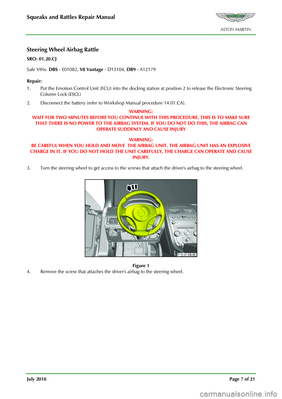
3. Turn the steering wheel to get access to the screws that attach the driver's airbag to the steering wheel.
Figure 1
4. Remove the screw that attaches the driver's airbag to the steering wheel.
Page 851 of 947
AML EOBD System Operation Summary
Rory O’Curry Aston Martin Lagonda CONFIDENTIAL 1 May 2009
[email protected] AML EOBD Monitors 07 ROC.doc Page 5 of 43
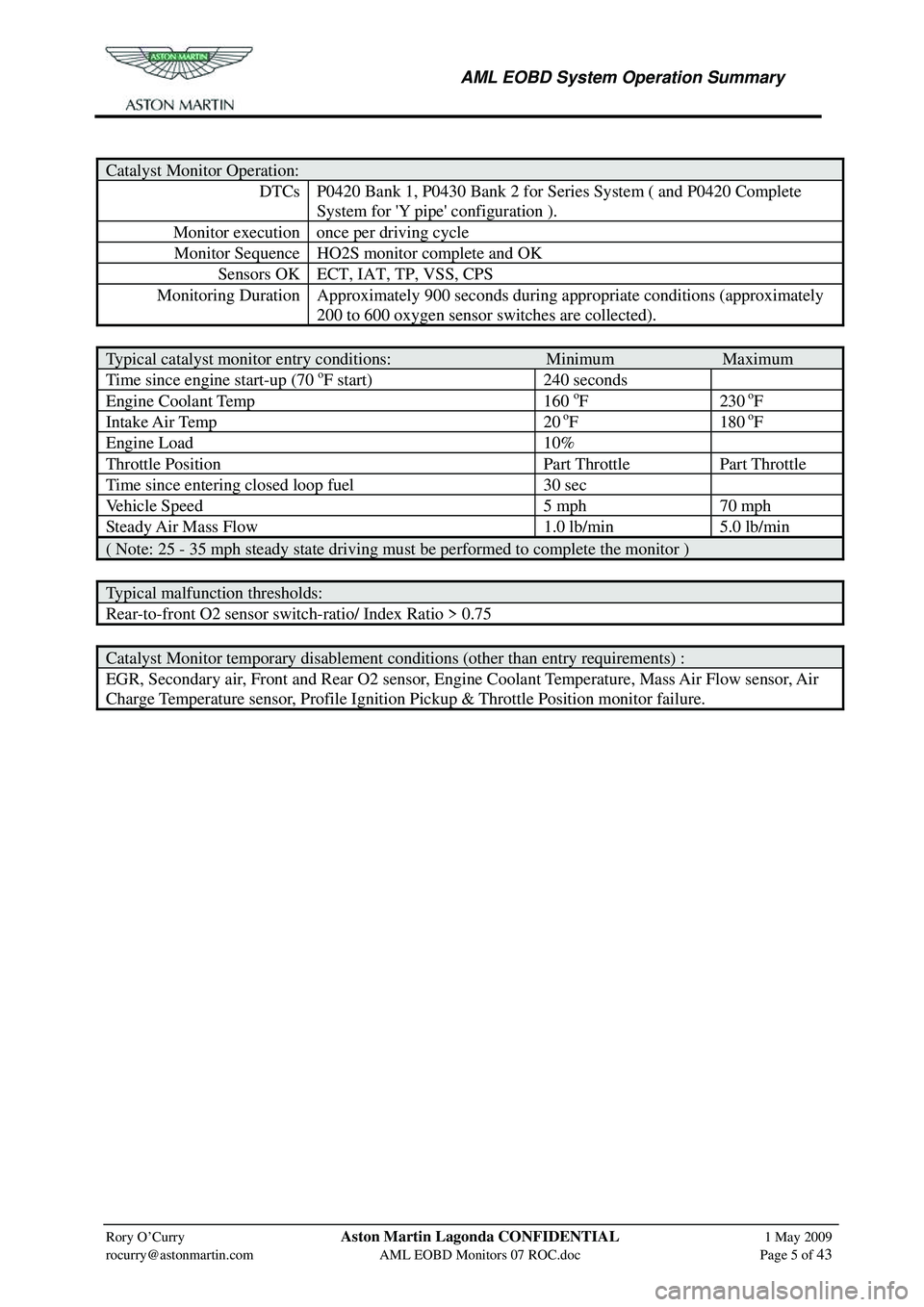
Catalyst Monitor Operation:
DTCs P0420 Bank 1, P0430 Bank 2 for Series System ( and P0420 Complete
System for 'Y pipe' configuration ).
Monitor execution once per driving cycle
Monitor Sequence HO2S monitor complete and OK
Sensors OK ECT, IAT, TP, VSS, CPS
Monitoring Duration Approximately 900 seconds dur ing appropriate conditions (approximately
200 to 600 oxygen sensor switches are collected).
Typical catalyst monitor entry conditions: Minimum Maximum
Time since engine start-up (70 oF start) 240 seconds
Engine Coolant Temp 160 oF 230 oF
Intake Air Temp 20 oF 180 oF
Engine Load 10%
Throttle Position Part Throttle Part Throttle
Time since entering closed loop fuel 30 sec
Vehicle Speed 5 mph 70 mph
Steady Air Mass Flow 1.0 lb/min 5.0 lb/min
( Note: 25 - 35 mph steady state driving must be performed to complete the monitor )
Typical malfunction thresholds:
Rear-to-front O2 sensor switch-ratio/ Index Ratio > 0.75
Catalyst Monitor temporary disablement conditions (other than entry requirements) :
EGR, Secondary air, Front and Rear O2 sensor, Engine Coolant Temperature, Mass Air Flow sensor, Air
Charge Temperature sensor, Profile Ignition Pickup & Throttle Position monitor failure.
Page 852 of 947
AML EOBD System Operation Summary
Rory O’Curry Aston Martin Lagonda CONFIDENTIAL 1 May 2009
[email protected] AML EOBD Monitors 07 ROC.doc Page 6 of 43
Misfire Monitor
Neural Network Misfire detection is used in order to achieve "full-range" capability. All software allows
for detection of any misfires that occur 6 engine revolutions after initially cranking the engine. This
meets the new OBD-II requirement to identify misfires within 2 engine revolutions after exceeding the
warm drive, idle rpm.
.
Neural Network System
The Neural Net Misfire (NNM) monitor uses a dedicated microprocessor in the PCM along with
crankshaft position, (36–tooth wheel), camshaft position, and engine load to determine engine misfire. A
neural network is different way of computing that uses a large number of simple processing elements with
a high degree of interconnection to process complex inform ation. It is based on the parallel architecture of
the brain. The processing elements have adaptive ch aracteristics (coefficients) that must be learned
through a process called training. During training, the netw ork is fed a sample set of data that consists of
the inputs along with the desired output (e.g. misfire/no misfire). The network coefficients are recursively
optimized so that the correct output is generated fro m the set of inputs and error is minimized. Once the
coefficients have been learned, the network can process "real" data.