oil level ASTON MARTIN V8 VANTAGE 2010 Owner's Guide
[x] Cancel search | Manufacturer: ASTON MARTIN, Model Year: 2010, Model line: V8 VANTAGE, Model: ASTON MARTIN V8 VANTAGE 2010Pages: 947, PDF Size: 43.21 MB
Page 311 of 947
Fuel Charging System (03.04)
Engine (03.00)
May 2007 Workshop Manual 3-4-5
17. Install fusebox bracket fixings.
18. Refit harness fir tree clips to cylinder head.
19. Refit engine breather hose.
20. Install VVT solenoid multiplug, position coil and CMP
harness (1x edge clip).
21. Install LH injectors (see Workshop Manual procedure
03.04.GH Injector - Fuel - LH Bank - Each - Renew).
22. Install ECM (see Workshop Manual procedure 03.14.BB Engine Control Module - RH Renew).
1. Install coils (see Workshop Manual procedure 03.07.HC
Coil Assembly - Engine Set - RH - Renew).
Fuel Injector - Each - LH Bank - Renew
Removal
1. Depressurise fuel rail (see Workshop Manual procedure 10.01.EK Fuel System - Depressurise).
2. Remove corner cross brace.
3. Disconnect breather hoses from cam cover (x2) for access.
4. Disconnect purge line from manifold (quickfit) and support clip for access.
5. Disconnect heater hose from pipe (quick fit).
6. Release heater hose (x2) and throttle body hose (x2) from support bracket.
7. Remove booster hose from manifold and support clip.
8. Remove harness support bracket (bolt x1, nut x2) release harness clips (fir tree x3).
9. Release pipe support bracket (nuts x2, bolts x2) move aside.
10. Disconnect IAT multiplug.
11. Disconnect injector multiplugs (x4).
12. Unclip injector harness from cam cover (x2).
13. Disconnect breather hose from manifold (quickfit).
14. Remove Injector to rail clip (for injector to be changed).
15. Remove fuel rail bolts (x2) and lift rail with remaining injectors (tie aside).
16. Remove injector from manifold.
Installation
1. Install new O-rings to remaining injectors (lube O-rings).
2. Install clip to new injector then injector into rail.
3. Install rail (with injectors) to manifold (bolt x2) (torque) (taking care each injector is aligned correctly).
4. Connect breather hose to manifold (quickfit).
5. Connect IAT multiplug.
6. Unclip injector harness from cam cover (x2).
7. Connect injector multiplugs (x4).
8. Install pipe support br acket (nuts x2, bolts x2). 9. Install harness support bracket (bolt x1, nut x2) release
harness clips (fir tree x3).
10. Connect booster hose to manifold and support clip.
11. Connect heater hose from pipe (quick fit).
12. Install heater hose (x2) and throttle body hose (x2) from support bracket.
13. Connect purge line to manifold and into support clip.
14. Connect breather hoses (x2) to cam cover.
15. Install corner cross brace (t orque bolts with vehicle on
level ground).
Fuel Injector - Each - RH Bank - Renew
Removal
1. Depressurise fuel rail (see Workshop Manual procedure 10.01.EK Fuel System - Depressurise).
2. Disconnect breather hose (quick fit) move aside.
3. Release harness fir tree clips (x3) from cylinder head and move aside.
4. Remove fuse box bracket fi xings (bolt and nut) (allows
movement).
5. Remove ECM (see Workshop Manual procedure 03.14.BB Engine Control Module - RH Renew).
6. Remove battery lead (1x nut and rubber cover) from fuse box (2x leads).
7. Remove multiplugs (x10) from fusebox.
8. Remove earth terminal (1x nut and rubber cover) from fusebox.
9. Remove fuse box from bracket (bolt x2).
10. Release harness fir tree clips (x3) from engine bracket.
11. Feed harness from inner wing and over engine to gain access to cam cover.
12. Remove purge pipe P-clip (bolt x1) and move pipe aside.
13. Remove harness bracket from engine (bolts x2, nut x1).
14. Release fuel feed hose from rail (clip x1) and move aside.
15. Disconnect heater hose from pipe (quick fit).
16. Release heater hose (clips x2) and EGR vacuum line
(clips x2) from bracket.
17. Release harness from coolan t pipe bracket (fir tree x3).
18. Disconnect EGR (x1), fuel rail pressure sensor (x1) and injector multiplugs (x4), move harness aside.
19. Remove coolant pipe bracket (nuts x2 and bolts x2).
20. Disconnect EGR vac pipe from sensor and manifold, move aside.
21. Remove Injector to rail clip (for injector to be changed).
22. Remove fuel rail bolts (x2) and lift rail with remaining injectors (tie aside).
23. Remove injector from manifold.
Repair Operation Time (ROT)
Repair Operation Time (ROT)
Page 312 of 947
Fuel Charging System (03.04)
Engine (03.00)3-4-6 Workshop Manual May 2007
Installation
1. Install new O-rings to remaining injectors (lube O-ringP-
clips).
2. Install clip to new injector then injector into rail.
3. Install rail (with injectors) to manifold (bolt x2) (torque)
(taking care each injector is aligned correctly).
4. Connect EGR vac pipe to sensor and manifold.
5. Install coolant pipe bracket (bolt x2, nut x2).
6. Connect EGR (x1), fuel rail pressure sensor (x1) and injector multiplugs (x4).
7. Refit harness to coolant pipe bracket (fir tree x3).
8. Connect heater hose to pipe (quick fit).
9. Refit heater hose (clipx2) and EGR vacuum lines (clips
x2) to bracket.
10. Install fuel feed pipe.
11. Install purge pipe P-clip.
12. Install harness bracket to engine.
13. Feed harness into inner wing area.
14. Install fusebox to bracket.
15. Install earth lead to fusebox.
16. Install battery lead to fusebox (1x nut and rubber cover).
17. Install multiplugs to fuse box.
18. Install fusebox bracket fixings.
19. Refit harness fir tree clips to cylinder head.
20. Refit engine breather hose.
21. Install VVT solenoid multiplug, position coil and CMP harness (1x edge clip).
22. Install ECM (see Workshop Manual procedure 03.14.BB Engine Control Module - RH Renew).
Engine Set - Fuel Injector - LH Bank -
Renew
Removal
1. Depressurise fuel rail (see Workshop Manual procedure 10.01.EK Fuel System - Depressurise).
2. Remove corner cross brace.
3. Disconnect breather hoses from cam cover (x2) for access.
4. Disconnect purge line from manifold (quickfit) and
support clip for access.
5. Disconnect heater hose from pipe (quick fit).
6. Release heater hose (x2) and throttle body hose (x2)
from support bracket.
7. Remove booster hose from manifold and support clip.
8. Remove harness support bracket (bolt x1, nut x2) release harness clips (fir tree x3). 9. Release pipe support bracket
(nuts x2, bolts x2) move
aside.
10. Disconnect IAT multiplug.
11. Disconnect injector multiplugs (x4).
12. Unclip injector harness from cam cover (x2).
13. Disconnect breather hose from manifold (quickfit).
14. Remove Injector to rail clips.
15. Remove fuel rail bolts (x2) and lift rail (tie aside).
16. Remove injectors from manifold.
Installation
1. Install clips on to new injectors then fit injectors into manifold.
2. Install rail onto injectors (taking care each injector is aligned correctly and the clip seats properly) and fit bolts
(x2) (torque).
3. Connect breather hose to manifold (quickfit).
4. Connect IAT multiplug.
5. Unclip injector harness from cam cover (x2).
6. Connect injector multiplugs (x4).
7. Install pipe support bracket (nuts x2, bolts x2).
8. Install harness support bracket (bolt x1, nut x2) release harness clips (fir tree x3).
9. Connect booster hose to manifold and support clip.
10. Connect heater hose from pipe (quick fit).
11. Install heater hose (x2) and throttle body hose (x2) from support bracket.
12. Connect purge line to manifold and into support clip.
13. Connect breather hoses (x2) to cam cover.
14. Install corner cross brace (torque bolts with vehicle on level ground).
Engine Set - Fuel Injector - RH Bank -
Renew
Removal
1. Depressurise fuel rail (see Workshop Manual procedure 10.01.EK Fuel System - Depressurise
2. Disconnect breather hose (quick fit) move aside.
3. Release harness fir tree clips (x3) from cylinder head and move aside.
4. Remove fuse box bracket fixings (bolt and nut) (allows movement).
5. Remove ECM (see Workshop Manual procedure 03.14.BB Engine Contro l Module - RH Renew).
6. Remove battery lead (1x nut and rubber cover) from fuse box (2x leads).
7. Remove multiplugs (x10) from fusebox.
Repair Operation Time (ROT)
Repair Operation Time (ROT)
ItemCode
Engine Set-Fuel Injector-RH Bank-
Renew LHD
03.04.GK
Engine Set-Fuel Injector-RH Bank-
Renew RHD
03.04.GP
Page 324 of 947
Emission Control (03.08)
Engine (03.00)3-8-2 Workshop Manual October 2005
6. Disconnect hose from engine (quickfit) and remove
hose.
Installation
1. Connect hose to engine (quickfit).
2. Clip hose to bracket.
3. Remove drain container.
4. Lower vehicle on ramp.
5. Install hose to oil separator (quickfit).
6. Install throttle body to air cleaner duct (clip x1).
7. Fill tank with approximately amount of displaced oil and replace cap.
8. Use handbook procedure to check oil level.
Oil Separator Assembly-Renew
Removal
1. Release clip and disconnect air cleaner duct from throttle body.
2. Disconnect hoses from oil separator (clips x2).
3. Remove separator (bolt x1) (place cloth to catch oil)
Installation
1. Install separator (bolt x1) (torque).
2. Install hoses to oil separator (clips x2).
3. Install throttle body to air cleaner duct (clip x1).
4. Use handbook procedure to check oil level.
Emissions Separator Hose-Renew
Removal
1. Move throttle body to air cleaner duct for access (clip x1).
2. Disconnect hose from oil separator (clips x1).
3. Disconnect hose from engi ne and remove (clips x1).
Installation
1. Connect hose to engine (clips x1).
2. Install hose to oil separator (clips x1).
3. Install throttle body to air cleaner duct (clip x1).
4. Use handbook procedure to check oil level.
Secondary Air Injection Pump and
Bracket Assembly-Renew
Removal
1. Disconnect vehicle battery. 2. Remove inlet manifold assembly (see Workshop Manual
procedure 03.01.BA Manifold Assembly - Intake Upper
- Renew).
3. Disconnect breather tube to secondary air pump (quickfit).
4. Disconnect vacuum tube from solenoid valve.
5. Disconnect vacuum tubes (x2) from actuator valves.
6. Loosen unions and disconnect secondary air injection tubes (x2).
7. Disconnect multiplug, air injection pump. Release multiplug from mounting bracket.
8. Release harness and vacuum tube fir tree clips (x6) from mounting bracket.
9. Remove bolts (x3), securing secondary air injection pump assembly to engine.
10. Remove secondary air injection pump assembly.
Installation
1. Position secondary air injection pump assembly, install and torque tighten bolts (x3).
2. Secure harness and vacuum tube fir tree clips (x6) in
mounting bracket.
3. Secure multiplug in bracket, connect multiplug.
4. Connect and torque tighten secondary air tube unions (x2).
5. Connect vacuum tubes to solenoid and actuator valves (x3).
6. Connect breather tube to secondary air injection pump.
7. Install inlet manifold assembly (see Workshop Manual procedure 03.01.BA Manifold Assembly - Intake Upper
- Renew).
8. Connect vehicle battery.
PCV Valve Assembly-Renew
Removal
1. Disconnect breather tube from PCV valve.
2. Remove bolts (x2) securing PCV valve, remove PCV valve.
Installation
1. Clean PCV valve and mating face.
2. Install PCV valve, install and torque tighten bolts (x2).
3. Connect breather tube to PCV valve.
Crank Vent Hose-Renew
Removal
1. Disconnect hose from cam cover (quickfit).
Repair Operation Time (ROT)
Repair Operation Time (ROT)
Repair Operation Time (ROT)
Repair Operation Time (ROT)
ItemCode
PCV Valve Assembly-Renew 03.08.DC
Repair Operation Time (ROT)
ItemCode
Crank Vent Hose-Renew 03.08.DD
Page 372 of 947
Engine Sealing (03.10)
Engine (03.00)3-10-14 Workshop Manual Issue 5, Janauary 2010
John Guest Cartridge in the Engine
Timing Cover - Repair
Removal
1. Open the bonnet.
2. Raise the vehicle and make it safe.
3. On Roadster models, remove the front undertray (Refer
to ’Centre Undertray - Remove and Install (Roadster
Only)’, page 1-2-1).
4. Put an approved container under the front cover to collect oil.
5. Disconnect the oil drain pipe from the John Guest
cartridge.
6. Let the oil drain.
7. Use a trim tool as a lever to remove the plastic collet from the cartridge.
8. Remove and discard the O-ring from the cartridge.
9. Clean all unwanted oil from the cartridge.
Install
1. Apply a layer of oil to the new O-ring .
2. Carefully install the new O- ring in the cartridge. Make
sure that the O-ring is in the correct position against the
shoulder of the cartridge.
3. Install the new plastic collet into the cartridge.
4. Connect the oil pipe into the cartridge.
5. Clean all unwanted oil from the area around the cartridge.
6. Remove the container of drained oil.
7. On Roadster models, install the front undertray (Refer to ’Centre Undertray - Remove and Install (Roadster
Only)’, page 1-2-1).
8. Lower the vehicle.
9. Remove the cap from the oil tank.
10. Add oil to the oil tank to the correct level.
11. Install the cap on the oil tank.
12. Start and operate the engine for approximately five minutes.
13. Stop the engine.
14. Wait five minutes for the oil to drain back to the sump.
15. Do a check of the oil le vel. Add oil if necessary. 16. Install the oil tank cap.
17. Close the bonnet.
Repair Operation Time (ROT)
Page 487 of 947
Brake Actuation System (06.06)
Brake System (06.00)
May 2007 Workshop Manual 6-6-1
Brake System (06.00)
Brake Actuation System (06.06)
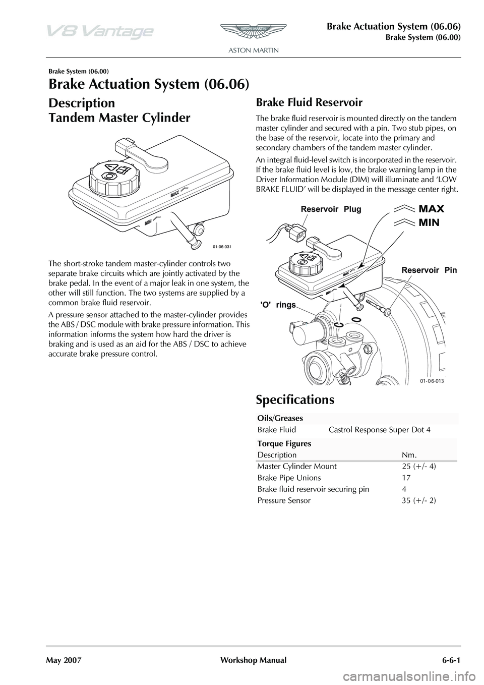
Description
Tandem Master Cylinder
The short-stroke tandem master-cylinder controls two
separate brake circuits which are jointly activated by the
brake pedal. In the event of a major leak in one system, the
other will still function. The two systems are supplied by a
common brake fluid reservoir.
A pressure sensor attached to the master-cylinder provides
the ABS / DSC module with brake pressure information. This
information informs the system how hard the driver is
braking and is used as an aid for the ABS / DSC to achieve
accurate brake pressure control.
Brake Fluid Reservoir
The brake fluid reservoir is mo unted directly on the tandem
master cylinder and secured with a pin. Two stub pipes, on
the base of the reservoir, locate into the primary and
secondary chambers of the tandem master cylinder.
An integral fluid-level switch is incorporated in the reservoir.
If the brake fluid level is low, the brake warning lamp in the
Driver Information Module (D IM) will illuminate and ‘LOW
BRAKE FLUID’ will be displayed in the message center right.
Specifications
Oils/Greases
Brake Fluid Castrol Response Super Dot 4
Torque Figures
DescriptionNm.
Master Cylinder Mount 25 (+/- 4)
Brake Pipe Unions 17
Brake fluid reservoir securing pin 4
Pressure Sensor 35 (+/- 2)
Page 515 of 947
Transmission Cooling (07.02)
Transmission (07.00)
May 2007 Workshop Manual 7-2-3
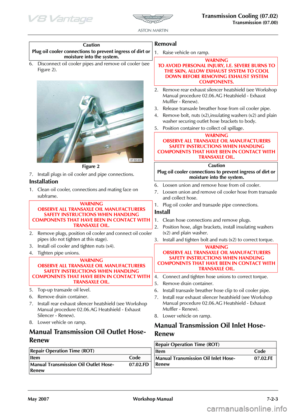
6. Disconnect oil cooler pipes and remove oil cooler (see
Figure 2).
7. Install plugs in oil cooler and pipe connections.
Installation
1. Clean oil cooler, connections and mating face on subframe.
2. Remove plugs, position oil cooler and connect oil cooler pipes (do not tighten at this stage).
3. Install oil cooler and tighten nuts (x4).
4. Tighten pipe unions.
5. Top-up transaxle oil level.
6. Remove drain container.
7. Install rear exhaust silencer heatshield (see Workshop
Manual procedure 02.06.AG Heatshield - Exhaust
Silencer - Renew).
8. Lower vehicle on ramp.
Manual Transmission Oil Outlet Hose-
Renew
Removal
1. Raise vehicle on ramp.
2. Remove rear exhaust silencer heatshield (see Workshop Manual procedure 02.06.AG Heatshield - Exhaust
Muffler - Renew).
3. Release transaxle breather hose from oil cooler pipe.
4. Remove bolt, nuts (x2),insulating washers (x2) and plain washer securing outlet hose brackets to body.
5. Position container to collect oil spillage.
6. Loosen union and remove hose from oil cooler.
7. Loosen union and remove oil cooler hose from transaxle and collect hose.
1. Plug oil cooler and transaxle pipe connections.
Install
1. Clean hose connections and remove plugs.
2. Position hose, align brackets, install insulating washers (x2) and plain washer.
3. Install and tighten bolt and nuts (x2) to correct torque.
4. Connect and tighten hose unions to correct torque.
5. Remove drain container.
6. Install transaxle breather hose clip to oil cooler pipe.
7. Install rear exhaust silencer heatshield (see Workshop Manual procedure 02.06.AG Heatshield - Exhaust
Muffler - Renew).
8. Lower vehicle on ramp.
Manual Transmission Oil Inlet Hose-
Renew
Caution
Plug oil cooler connections to prevent ingress of dirt or moisture into the system.
Figure 2
WA R N I N G
OBSERVE ALL TRANSAXLE OIL MANUFACTURERS SAFETY INSTRUCTIONS WHEN HANDLING
COMPONENTS THAT HAVE BEEN IN CONTACT WITH TRANSAXLE OIL.
WA R N I N G
OBSERVE ALL TRANSAXLE OIL MANUFACTURERS SAFETY INSTRUCTIONS WHEN HANDLING
COMPONENTS THAT HAVE BEEN IN CONTACT WITH
TRANSAXLE OIL.
Repair Operation Time (ROT)
07-02-003
WA R N I N G
TO AVOID PERSONAL INJURY, I.E. SEVERE BURNS TO THE SKIN, ALLOW EXHAUST SYSTEM TO COOL
DOWN BEFORE REMOVING EXHAUST SYSTEM COMPONENTS.
WA R N I N G
OBSERVE ALL TRANSAXLE OIL MANUFACTURERS SAFETY INSTRUCTIONS WHEN HANDLING
COMPONENTS THAT HAVE BEEN IN CONTACT WITH
TRANSAXLE OIL.
Caution
Plug oil cooler connections to prevent ingress of dirt or moisture into the system.
WA R N I N G
OBSERVE ALL TRANSAXLE OIL MANUFACTURERS SAFETY INSTRUCTIONS WHEN HANDLING
COMPONENTS THAT HAVE BEEN IN CONTACT WITH
TRANSAXLE OIL.
Repair Operation Time (ROT)
Page 524 of 947
Manual Transmission (07.03)
Transmission (07.00)7-3-8 Workshop Manual Issue 5, January 2010
32. Install the exhaust front mount.
33. Clean the component mating faces.
34. Apply an applicable sealant to the component mating faces.
35. Install the exhaust centre pipe.
36. Install and tighten the four bolts that attach the exhaust centre pipe to the exhaust front mount.
37. Put the clamps into position on the exhaust pipes.
38. Loosely install the four bolts that attach the exhaust centre pipe to the rear silencer.
39. Align the exhaust assembly.
40. Tighten the two clamps that attach the exhaust centre pipe to the catalytic converters.
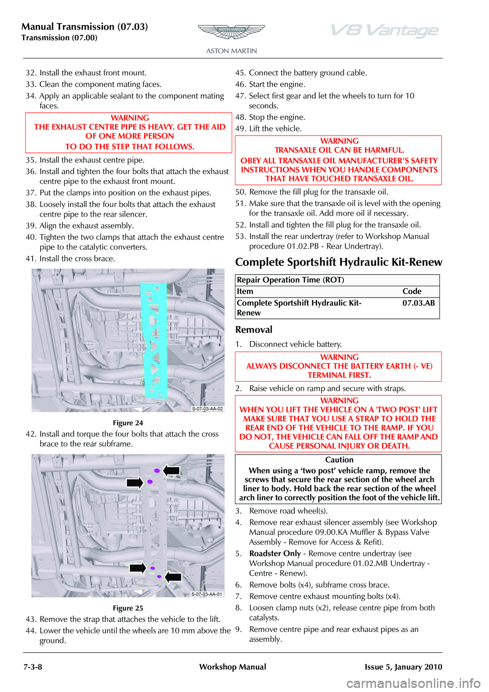
41. Install the cross brace.
Figure 24
42. Install and torque the four bolts that attach the cross brace to the rear subframe.
Figure 25
43. Remove the strap that attaches the vehicle to the lift.
44. Lower the vehicle until the wheels are 10 mm above the ground. 45. Connect the battery ground cable.
46. Start the engine.
47. Select first gear and let the wheels to turn for 10
seconds.
48. Stop the engine.
49. Lift the vehicle.
50. Remove the fill plug for the transaxle oil.
51. Make sure that the transaxle oil is level with the opening for the transaxle oil. Add more oil if necessary.
52. Install and tighten the fill plug for the transaxle oil.
53. Install the rear undertray (refer to Workshop Manual
procedure 01.02.PB - Rear Undertray).
Complete Sportshift Hydraulic Kit-Renew
Removal
1. Disconnect vehicle battery.
2. Raise vehicle on ramp and secure with straps.
3. Remove road wheel(s).
4. Remove rear exhaust silencer assembly (see Workshop Manual procedure 09.00.KA Muffler & Bypass Valve
Assembly - Remove for Access & Refit).
5. Roadster Only - Remove centre undertray (see
Workshop Manual procedure 01.02.MB Undertray -
Centre - Renew).
6. Remove bolts (x4), subframe cross brace.
7. Remove centre exhaust mounting bolts (x4).
8. Loosen clamp nuts (x2), release centre pipe from both catalysts.
9. Remove centre pipe and rear exhaust pipes as an
assembly.
WAR NI NG
THE EXHAUST CENTRE PIPE IS HEAVY. GET THE AID OF ONE MORE PERSON
TO DO THE STEP THAT FOLLOWS.
WAR NI NG
TRANSAXLE OIL CAN BE HARMFUL.
OBEY ALL TRANSAXLE OIL MANUFACTURER’S SAFETY INSTRUCTIONS WHEN YO U HANDLE COMPONENTS
THAT HAVE TOUCHED TRANSAXLE OIL.
Repair Operation Time (ROT)
ItemCode
Complete Sportshift Hydraulic Kit-
Renew 07.03.AB
WAR NI NG
ALWAYS DISCONNECT THE BATTERY EARTH (- VE)
TERMINAL FIRST.
WAR NI NG
WHEN YOU LIFT THE VEHICLE ON A 'TWO POST' LIFT MAKE SURE THAT YOU USE A STRAP TO HOLD THE REAR END OF THE VEHICLE TO THE RAMP. IF YOU
DO NOT, THE VEHICLE CAN FALL OFF THE RAMP AND CAUSE PERSONAL INJURY OR DEATH.
Caution
When using a ‘two post’ vehicle ramp, remove the
screws that secure the rear section of the wheel arch
liner to body. Hold back the rear section of the wheel
arch liner to correctly position the foot of the vehicle lift.
Page 547 of 947
Manual Transmission (07.03)
Transmission (07.00)
Issue 5, January 2010 Workshop Manual 7-3-31
43. Disconnect the electrical connector from the wiring
harness for the torque tube.
44. Remove the bolt that attaches the bracket for the electrical connector.
45. Move the bracket for the electrical connector away.
46. Remove the bolt that attaches the transaxle ground cable to the transaxle Automatic Shift Mechanism (ASM)
pump.
47. Disconnect the electrical connector from the ASM
pump.
48. Release the wiring harness for the ASM pump from the two clips that attach it to the transxle.
49. Identify and disconnect the five electrical connectors from the transaxle.
50. Disconnect the electrical connector from the selector
position sensor.
51. Remove the bolt that attaches the ground cable eyelet to the transaxle.
52. Put the wiring harness under the hydraulic pipe for the clutch, and move it away from the transaxle.
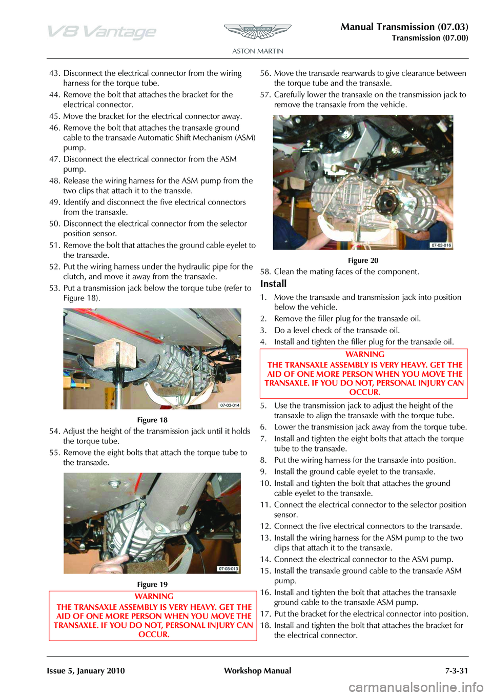
53. Put a transmission jack belo w the torque tube (refer to
Figure 18).
Figure 18
54. Adjust the height of the tran smission jack until it holds
the torque tube.
55. Remove the eight bolts that attach the torque tube to the transaxle.
Figure 19
56. Move the transaxle rearwards to give clearance between the torque tube and the transaxle.
57. Carefully lower the transaxle on the transmission jack to remove the transaxle from the vehicle.
Figure 20
58. Clean the mating faces of the component.
Install
1. Move the transaxle and transm ission jack into position
below the vehicle.
2. Remove the filler plug for the transaxle oil.
3. Do a level check of the transaxle oil.
4. Install and tighten the filler plug for the transaxle oil.
5. Use the transmission jack to adjust the height of the transaxle to align the transaxle with the torque tube.
6. Lower the transmission jack away from the torque tube.
7. Install and tighten the eight bolts that attach the torque tube to the transaxle.
8. Put the wiring harness for the transaxle into position.
9. Install the ground cable eyelet to the transaxle.
10. Install and tighten the bolt that attaches the ground cable eyelet to the transaxle.
11. Connect the electrical connector to the selector position sensor.
12. Connect the five electrical connectors to the transaxle.
13. Install the wiring harness for the ASM pump to the two clips that attach it to the transaxle.
14. Connect the electrical connector to the ASM pump.
15. Install the transaxle ground cable to the transaxle ASM pump.
16. Install and tighten the bolt that attaches the transaxle ground cable to the transaxle ASM pump.
17. Put the bracket for the electrical connector into position.
18. Install and tighten the bolt that attaches the bracket for the electrical connector.
WARNING
THE TRANSAXLE ASSEMBLY IS VERY HEAVY. GET THE AID OF ONE MORE PERSON WHEN YOU MOVE THE
TRANSAXLE. IF YOU DO NOT, PERSONAL INJURY CAN OCCUR.
WARNING
THE TRANSAXLE ASSEMBLY IS VERY HEAVY. GET THE AID OF ONE MORE PERSON WHEN YOU MOVE THE
TRANSAXLE. IF YOU DO NOT, PERSONAL INJURY CAN
OCCUR.
Page 549 of 947
Manual Transmission (07.03)
Transmission (07.00)
Issue 5, January 2010 Workshop Manual 7-3-33
43. Install the tunnel reinforcement plate.
44. Install and torque the eight bolts that attach the tunnel reinforcement plate to the body.
45. Install floor heatshield.
46. Install and tighten the four bolts that attach the floor heat shield to the body.
47. Install the exhaust front mount.
48. Clean the component mating faces.
49. Apply an applicable sealant to the component mating faces.
50. Install the exhaust centre pipe.
51. Install and tighten the four bolts that attach the exhaust centre pipe to the exhaust front mount.
52. Put the clamps into position on the exhaust pipes.
53. Loosely install the four bolts that attach the exhaust centre pipe to the rear silencer.
54. Align the exhaust assembly.
55. Tighten the two clamps that attach the exhaust centre pipe to the catalytic converters.
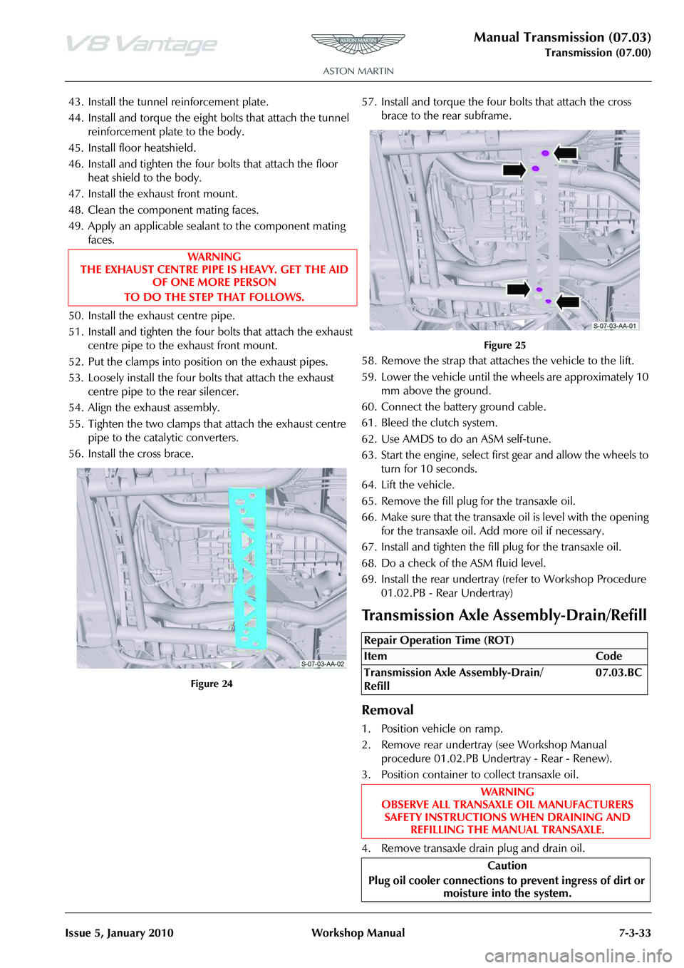
56. Install the cross brace.
Figure 24
57. Install and torque the four bolts that attach the cross brace to the rear subframe.
Figure 25
58. Remove the strap that attaches the vehicle to the lift.
59. Lower the vehicle until the wheels are approximately 10 mm above the ground.
60. Connect the battery ground cable.
61. Bleed the clutch system.
62. Use AMDS to do an ASM self-tune.
63. Start the engine, select first gear and allow the wheels to turn for 10 seconds.
64. Lift the vehicle.
65. Remove the fill plug for the transaxle oil.
66. Make sure that the transaxle oil is level with the opening for the transaxle oil. Add more oil if necessary.
67. Install and tighten the fill plug for the transaxle oil.
68. Do a check of the ASM fluid level.
69. Install the rear undertray (refer to Workshop Procedure 01.02.PB - Rear Undertray)
Removal
1. Position vehicle on ramp.
2. Remove rear undertray (see Workshop Manual procedure 01.02.PB Undertray - Rear - Renew).
3. Position container to collect transaxle oil.
4. Remove transaxle drain plug and drain oil.
WA R N I N G
THE EXHAUST CENTRE PIPE IS HEAVY. GET THE AID
OF ONE MORE PERSON
TO DO THE STEP THAT FOLLOWS.
Repair Operation Time (ROT)
Page 550 of 947
Manual Transmission (07.03)
Transmission (07.00)7-3-34 Workshop Manual Issue 5, January 2010
5. Loosen and disconnect oil c ooler pipes and allow oil in
the oil cooler system to drain into container.
6. Remove filler plug.
7. Discard sealing washers (x2).
Install
1. Clean drain and filler plugs.
2. Install new sealing washers to filler and drain plugs.
3. Install drain plug and tighten to correct torque.
4. Install oil cooler pipes and tighten unions to correct torque.
5. Fill transaxle with the correct grade and quantity of oil.
6. Install filler plug and tighten to the correct torque.
7. Install rear undertray (see Workshop Manual procedure 01.02.PB Undertray - Rear - Renew).
8. Lower vehicle on ramp.
9. Road test vehicle.
10. Position vehicle on ramp.
11. Check and top-up transaxle oil level.
12. Lower vehicle on ramp.
Transaxle Assembly-Renew
Removal
1. Remove transaxle assembly (see Workshop Manual procedure 07.03.AA Transaxle Assembly - Manual -
Remove for Access & Refit).
2. Attach slings to transaxle and connect suitable hoist.
3. With assistance, remove transaxle from lifter and position on work bench.
4. Lower hoist and remove slings.
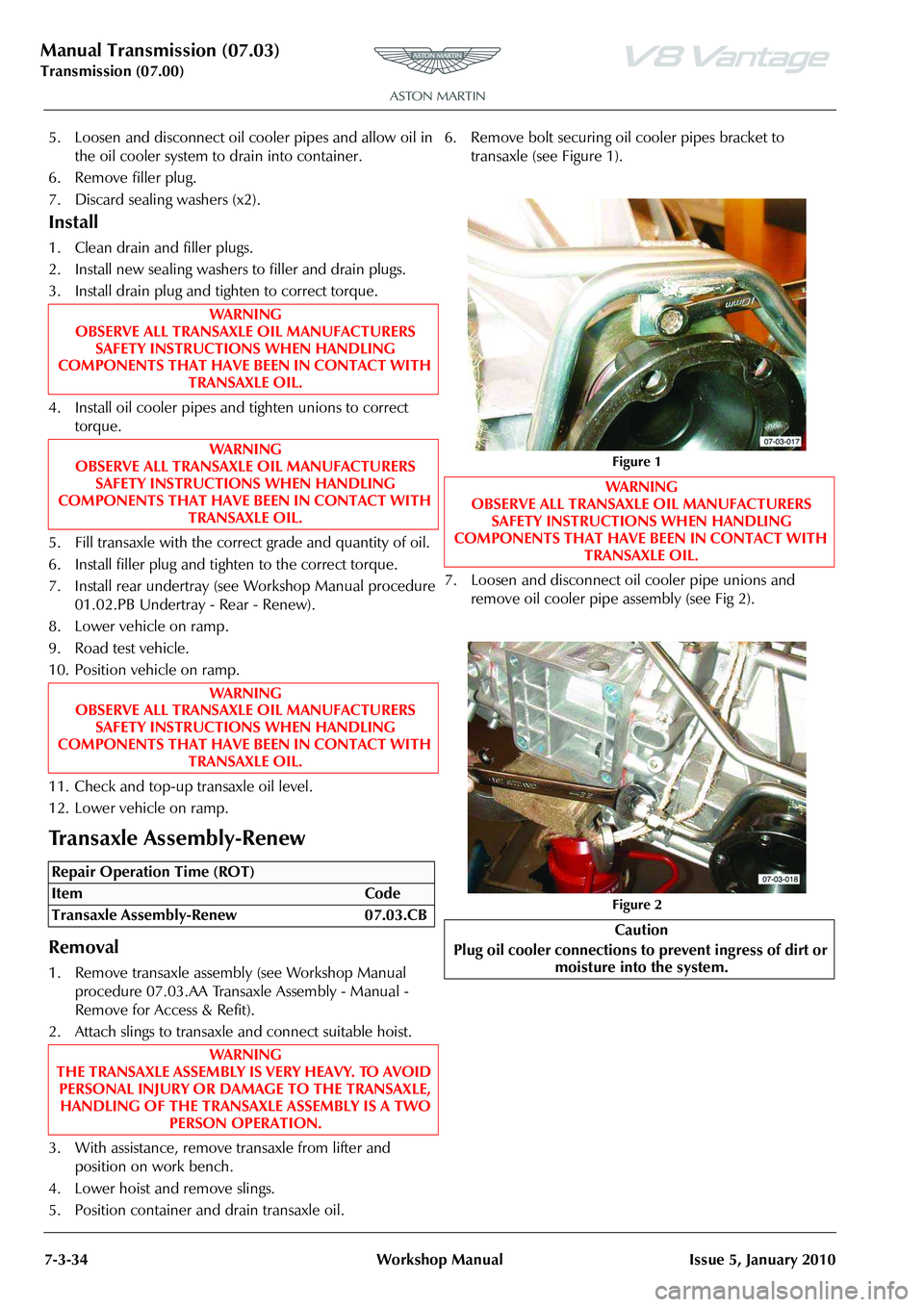
5. Position container and drain transaxle oil. 6. Remove bolt securing oi
l cooler pipes bracket to
transaxle (see Figure 1).
7. Loosen and disconnect oi l cooler pipe unions and
remove oil cooler pipe assembly (see Fig 2).
WAR NI NG
OBSERVE ALL TRANSAXLE OIL MANUFACTURERS
SAFETY INSTRUCTIONS WHEN HANDLING
COMPONENTS THAT HAVE BEEN IN CONTACT WITH TRANSAXLE OIL.
WAR NI NG
OBSERVE ALL TRANSAXLE OIL MANUFACTURERS
SAFETY INSTRUCTIONS WHEN HANDLING
COMPONENTS THAT HAVE BEEN IN CONTACT WITH TRANSAXLE OIL.
WAR NI NG
OBSERVE ALL TRANSAXLE OIL MANUFACTURERS
SAFETY INSTRUCTIONS WHEN HANDLING
COMPONENTS THAT HAVE BEEN IN CONTACT WITH TRANSAXLE OIL.
Repair Operation Time (ROT)
Figure 1
WAR NI NG
OBSERVE ALL TRANSAXLE OIL MANUFACTURERS SAFETY INSTRUCTIONS WHEN HANDLING
COMPONENTS THAT HAVE BEEN IN CONTACT WITH
TRANSAXLE OIL.
Figure 2
Caution
Plug oil cooler connections to prevent ingress of dirt or
moisture into the system.