Sd card ASTON MARTIN V8 VANTAGE 2010 Repair Manual
[x] Cancel search | Manufacturer: ASTON MARTIN, Model Year: 2010, Model line: V8 VANTAGE, Model: ASTON MARTIN V8 VANTAGE 2010Pages: 947, PDF Size: 43.21 MB
Page 417 of 947
Engine Management System (03.14)
Engine (03.00)
Issue 5, Janauary 2010 Workshop Manual 3-14-1
Engine (03.00)
Engine Management System (03.14)
Maintenance
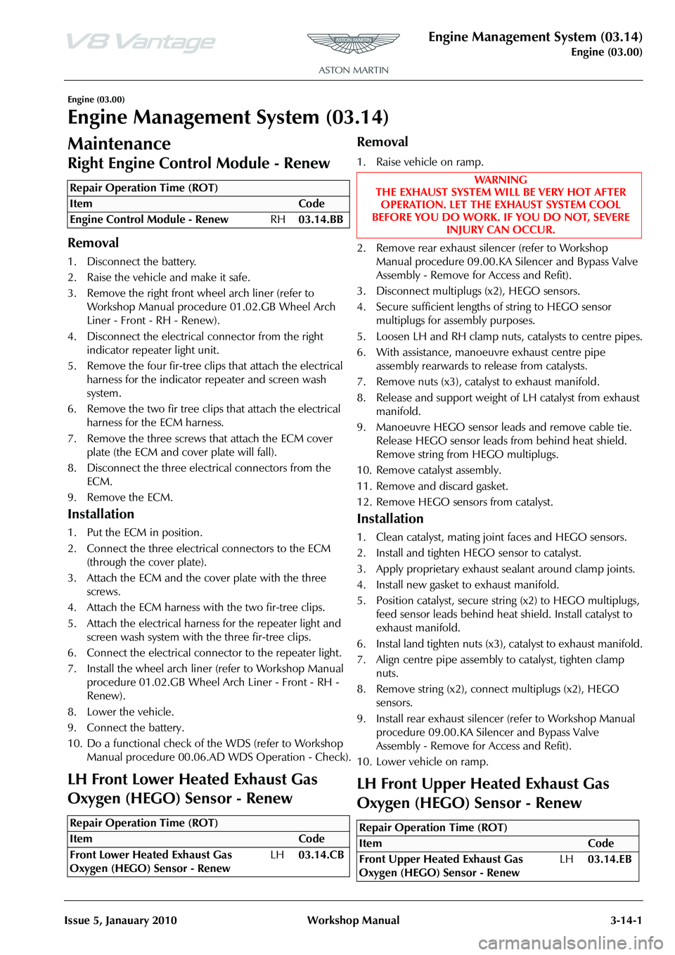
LH Front Lower Heated Exhaust Gas
Oxygen (HEGO) Sensor - Renew
Removal
1. Raise vehicle on ramp.
2. Remove rear exhaust silencer (refer to Workshop Manual procedure 09.00.KA Silencer and Bypass Valve
Assembly - Remo ve for Access and Refit).
3. Disconnect multiplugs (x2), HEGO sensors.
4. Secure sufficient lengths of string to HEGO sensor multiplugs for assembly purposes.
5. Loosen LH and RH clamp nuts, catalysts to centre pipes.
6. With assistance, manoeuvre exhaust centre pipe assembly rearwards to release from catalysts.
7. Remove nuts (x3), catalyst to exhaust manifold.
8. Release and support weight of LH catalyst from exhaust
manifold.
9. Manoeuvre HEGO sensor leads and remove cable tie. Release HEGO sensor leads from behind heat shield.
Remove string from HEGO multiplugs.
10. Remove catalyst assembly.
11. Remove and discard gasket.
12. Remove HEGO sens ors from catalyst.
Installation
1. Clean catalyst, mating joint faces and HEGO sensors.
2. Install and tighten HEGO sensor to catalyst.
3. Apply proprietary exhaust se alant around clamp joints.
4. Install new gasket to exhaust manifold.
5. Position catalyst, secure string (x2) to HEGO multiplugs, feed sensor leads behind heat shield. Install catalyst to
exhaust manifold.
6. Instal land tighten nuts (x3), catalyst to exhaust manifold.
7. Align centre pipe assembly to catalyst, tighten clamp
nuts.
8. Remove string (x2), conne ct multiplugs (x2), HEGO
sensors.
9. Install rear exhaust silencer (refer to Workshop Manual procedure 09.00.KA Silencer and Bypass Valve
Assembly - Remo ve for Access and Refit).
10. Lower vehicle on ramp.
LH Front Upper Heated Exhaust Gas
Oxygen (HEGO) Sensor - Renew
Repair Operation Time (ROT)
Repair Operation Time (ROT)
WA R N I N G
THE EXHAUST SYSTEM WILL BE VERY HOT AFTER OPERATION. LET THE EXHAUST SYSTEM COOL
BEFORE YOU DO WORK. IF YOU DO NOT, SEVERE
INJURY CAN OCCUR.
Repair Operation Time (ROT)
Page 418 of 947
Engine Management System (03.14)
Engine (03.00)3-14-2 Workshop Manual Issue 5, Janauary 2010
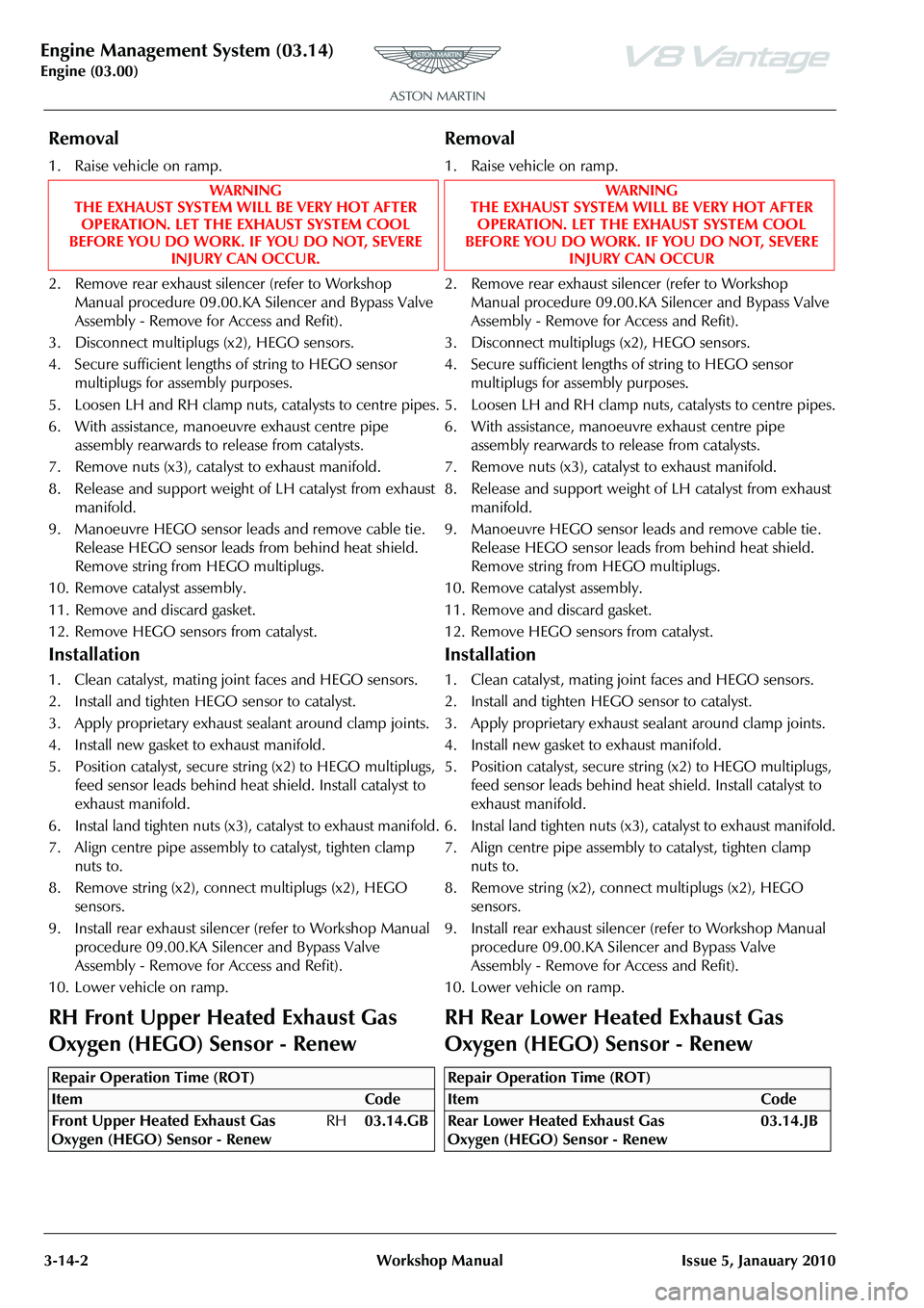
Removal
1. Raise vehicle on ramp.
2. Remove rear exhaust silencer (refer to Workshop Manual procedure 09.00.KA Silencer and Bypass Valve
Assembly - Remove for Access and Refit).
3. Disconnect multiplugs (x2), HEGO sensors.
4. Secure sufficient lengths of string to HEGO sensor multiplugs for assembly purposes.
5. Loosen LH and RH clamp nuts, catalysts to centre pipes.
6. With assistance, manoeuvre exhaust centre pipe assembly rearwards to release from catalysts.
7. Remove nuts (x3), catalyst to exhaust manifold.
8. Release and support weight of LH catalyst from exhaust manifold.
9. Manoeuvre HEGO sensor leads and remove cable tie. Release HEGO sensor leads from behind heat shield.
Remove string from HEGO multiplugs.
10. Remove catalyst assembly.
11. Remove and discard gasket.
12. Remove HEGO sensors from catalyst.
Installation
1. Clean catalyst, mating joint faces and HEGO sensors.
2. Install and tighten HEGO sensor to catalyst.
3. Apply proprietary exhaust sealant around clamp joints.
4. Install new gasket to exhaust manifold.
5. Position catalyst, secure string (x2) to HEGO multiplugs, feed sensor leads behind heat shield. Install catalyst to
exhaust manifold.
6. Instal land tighten nuts (x3), catalyst to exhaust manifold.
7. Align centre pipe assembly to catalyst, tighten clamp nuts to.
8. Remove string (x2), connect multiplugs (x2), HEGO sensors.
9. Install rear exhaust silencer (refer to Workshop Manual
procedure 09.00.KA Silencer and Bypass Valve
Assembly - Remove for Access and Refit).
10. Lower vehicle on ramp.
RH Front Upper Heated Exhaust Gas
Oxygen (HEGO) Sensor - Renew
Removal
1. Raise vehicle on ramp.
2. Remove rear exhaust silencer (refer to Workshop Manual procedure 09.00.KA Silencer and Bypass Valve
Assembly - Remove for Access and Refit).
3. Disconnect multiplugs (x2), HEGO sensors.
4. Secure sufficient lengths of string to HEGO sensor
multiplugs for assembly purposes.
5. Loosen LH and RH clamp nuts, catalysts to centre pipes.
6. With assistance, manoeuvre exhaust centre pipe assembly rearwards to release from catalysts.
7. Remove nuts (x3), catalyst to exhaust manifold.
8. Release and support weight of LH catalyst from exhaust
manifold.
9. Manoeuvre HEGO sensor leads and remove cable tie. Release HEGO sensor leads from behind heat shield.
Remove string from HEGO multiplugs.
10. Remove catalyst assembly.
11. Remove and discard gasket.
12. Remove HEGO sensors from catalyst.
Installation
1. Clean catalyst, mating joint faces and HEGO sensors.
2. Install and tighten HEGO sensor to catalyst.
3. Apply proprietary exhaust sealant around clamp joints.
4. Install new gasket to exhaust manifold.
5. Position catalyst, secure string (x2) to HEGO multiplugs, feed sensor leads behind heat shield. Install catalyst to
exhaust manifold.
6. Instal land tighten nuts (x3), catalyst to exhaust manifold.
7. Align centre pipe assembly to catalyst, tighten clamp nuts to.
8. Remove string (x2), connect multiplugs (x2), HEGO sensors.
9. Install rear exhaust silencer (refer to Workshop Manual procedure 09.00.KA Silencer and Bypass Valve
Assembly - Remove for Access and Refit).
10. Lower vehicle on ramp.
RH Rear Lower Heated Exhaust Gas
Oxygen (HEGO) Sensor - Renew
WAR NI NG
THE EXHAUST SYSTEM WILL BE VERY HOT AFTER OPERATION. LET THE EXHAUST SYSTEM COOL
BEFORE YOU DO WORK. IF YOU DO NOT, SEVERE INJURY CAN OCCUR.
Repair Operation Time (ROT)
WAR NI NG
THE EXHAUST SYSTEM WILL BE VERY HOT AFTER OPERATION. LET THE EXHAUST SYSTEM COOL
BEFORE YOU DO WORK. IF YOU DO NOT, SEVERE INJURY CAN OCCUR
Repair Operation Time (ROT)
ItemCode
Rear Lower Heated Exhaust Gas
Oxygen (HEGO) Sensor - Renew 03.14.JB
Page 419 of 947
Engine Management System (03.14)
Engine (03.00)
Issue 5, Janauary 2010 Workshop Manual 3-14-3
Removal
1. Raise vehicle on ramp.
2. Remove rear exhaust silencer (refer to Workshop Manual procedure 09.00.KA Silencer and Bypass Valve
Assembly - Remove for Access and Refit).
3. Disconnect multiplugs (x2), HEGO sensors.
4. Secure sufficient lengths of string to HEGO sensor multiplugs for assembly purposes.
5. Loosen LH and RH clamp nuts, catalysts to centre pipes.
6. With assistance, manoeuvre exhaust centre pipe assembly rearwards to release from catalysts.
7. Remove nuts (x3), catalyst to exhaust manifold.
8. Release and support weight of LH catalyst from exhaust manifold.
9. Manoeuvre HEGO sensor leads and remove cable tie. Release HEGO sensor leads from behind heat shield.
Remove string from HEGO multiplugs.
10. Remove catalyst assembly.
11. Remove and discard gasket.
12. Remove HEGO sensors from catalyst.
Installation
1. Clean catalyst, mating joint faces and HEGO sensors.
2. Install and tighten HEGO sensor to catalyst.
3. Apply proprietary exhaust se alant around clamp joints.
4. Install new gasket to exhaust manifold.
5. Position catalyst, secure string (x2) to HEGO multiplugs, feed sensor leads behind heat shield. Install catalyst to
exhaust manifold.
6. Instal land tighten nuts (x3), catalyst to exhaust manifold.
7. Align centre pipe assembly to catalyst, tighten clamp
nuts to.
8. Remove string (x2), conne ct multiplugs (x2), HEGO
sensors.
9. Install rear exhaust silencer (refer to Workshop Manual procedure 09.00.KA Silencer and Bypass Valve
Assembly - Remove for Access and Refit).
10. Lower vehicle on ramp.
Left Side Powertrain Control Module
(PCM) (Coupe Only) - Remove and
Install
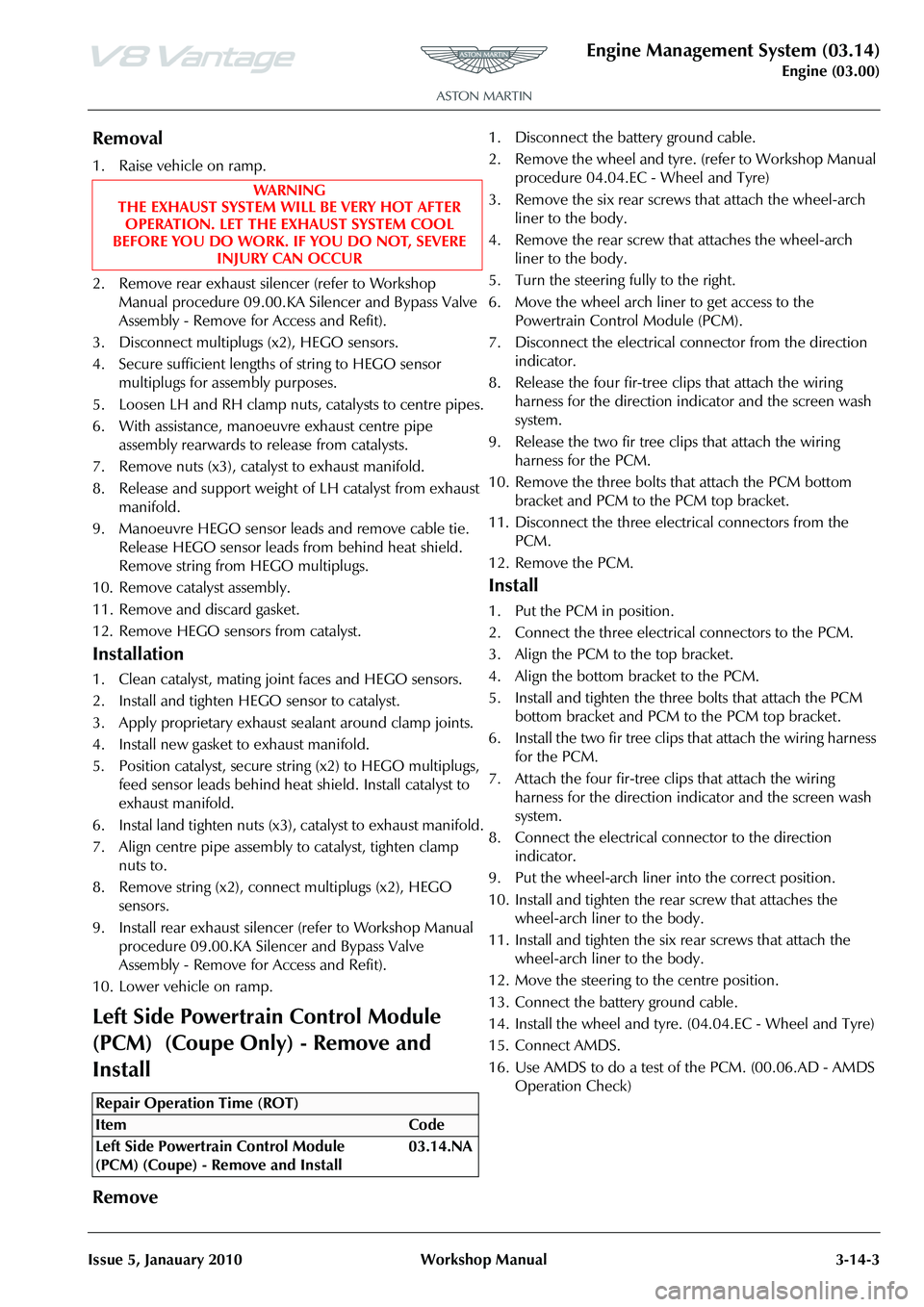
Remove
1. Disconnect the ba ttery ground cable.
2. Remove the wheel and tyre. (refer to Workshop Manual procedure 04.04.EC - Wheel and Tyre)
3. Remove the six rear screws that attach the wheel-arch liner to the body.
4. Remove the rear screw that attaches the wheel-arch liner to the body.
5. Turn the steering fully to the right.
6. Move the wheel arch liner to get access to the Powertrain Control Module (PCM).
7. Disconnect the electrical connector from the direction
indicator.
8. Release the four fi r-tree clips that attach the wiring
harness for the direction indi cator and the screen wash
system.
9. Release the two fir tree clips that attach the wiring harness for the PCM.
10. Remove the three bolts that attach the PCM bottom bracket and PCM to the PCM top bracket.
11. Disconnect the three electrical connectors from the PCM.
12. Remove the PCM.
Install
1. Put the PCM in position.
2. Connect the three electrical connectors to the PCM.
3. Align the PCM to the top bracket.
4. Align the bottom bracket to the PCM.
5. Install and tighten the three bolts that attach the PCM bottom bracket and PCM to the PCM top bracket.
6. Install the two fir tree clips that attach the wiring harness for the PCM.
7. Attach the four fir-tree cl ips that attach the wiring
harness for the direction indi cator and the screen wash
system.
8. Connect the electrical connector to the direction indicator.
9. Put the wheel-arch liner into the correct position.
10. Install and tighten the rear screw that attaches the wheel-arch liner to the body.
11. Install and tighten the six rear screws that attach the wheel-arch liner to the body.
12. Move the steering to the centre position.
13. Connect the battery ground cable.
14. Install the wheel and tyre. (04.04.EC - Wheel and Tyre)
15. Connect AMDS.
16. Use AMDS to do a test of the PCM. (00.06.AD - AMDS Operation Check)
WA R N I N G
THE EXHAUST SYSTEM WILL BE VERY HOT AFTER OPERATION. LET THE EXHAUST SYSTEM COOL
BEFORE YOU DO WORK. IF YOU DO NOT, SEVERE
INJURY CAN OCCUR
Repair Operation Time (ROT)
Page 469 of 947
Driveshaft (05.01)
Driveline (05.00)
May 2007 Workshop Manual 5-1-7
6. Manual Only - Bleed clutch hydraulics.
7. Install LH exhaust manifold (see Workshop Manual 09.00.CB Manifold - Exhaust - LH - Renew).
8. Install transaxle (see Workshop Manual07.03.AA Transaxle Assembly - Manual - Remove for Access and
Refit).
9. Lower vehicle on ramp.
10. Connect vehicle battery.
RH/LH Drive Shaft Assembly-Renew
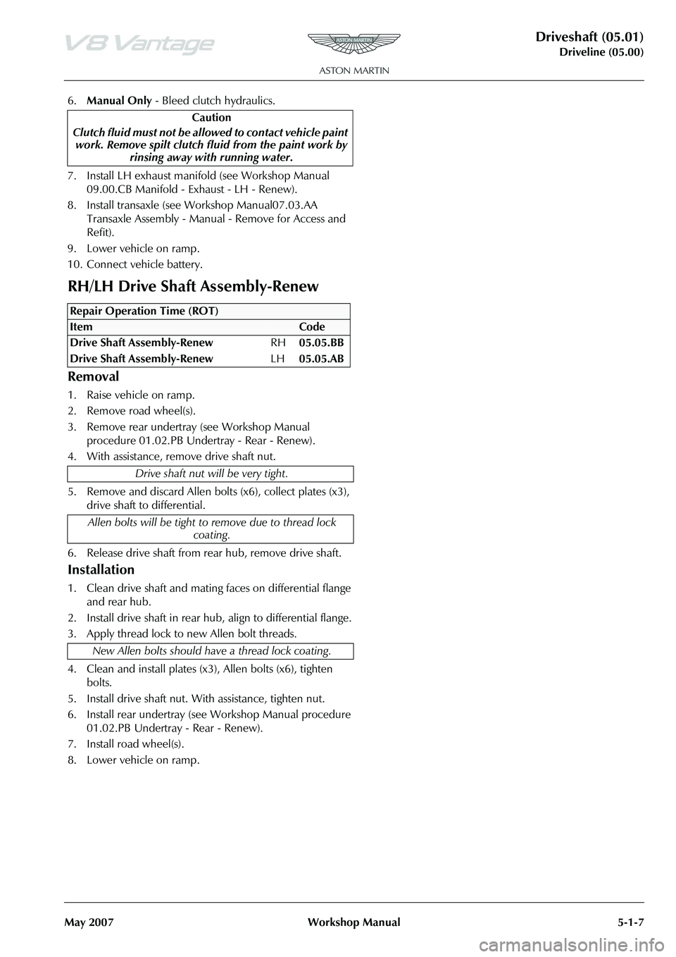
Removal
1. Raise vehicle on ramp.
2. Remove road wheel(s).
3. Remove rear undertray (see Workshop Manual procedure 01.02.PB Undertray - Rear - Renew).
4. With assistance, remove drive shaft nut.
5. Remove and discard Allen bolt s (x6), collect plates (x3),
drive shaft to differential.
6. Release drive shaft from rear hub, remove drive shaft.
Installation
1. Clean drive shaft and mating faces on differential flange and rear hub.
2. Install drive shaft in rear hub, align to differential flange.
3. Apply thread lock to new Allen bolt threads.
4. Clean and install plates (x3), Allen bolts (x6), tighten bolts.
5. Install drive shaft nut. With assistance, tighten nut.
6. Install rear undertray (see Workshop Manual procedure 01.02.PB Undertray - Rear - Renew).
7. Install road wheel(s).
8. Lower vehicle on ramp. Caution
Clutch fluid must not be allowed to contact vehicle paint work. Remove spilt clutch fl uid from the paint work by
rinsing away with running water.
Repair Operation Time (ROT)
Page 476 of 947
Front Disc Brake (06.03)
Brake Systems (06.00)6-3-4 Workshop Manual Version 6, March 2010
Front Caliper-Renew
Removal
1. Raise the vehicle and make it safe.
2. Remove the road wheel.
3. Remove the pad wear sensor.
4. Move the caliper pistons into to the caliper to release the pads.
5. Remove the brake pad retaining pins and anti-rattle spring.
6. Remove the pads and shims from the caliper.
7. Disconnect the brake hose.
8. Install sealing plugs into the open brake-pipe port of the caliper and the hose to prevent contamination.
9. Remove and discard the two caliper attachment bolts.
10. Remove the caliper.
Installation
1. Clean the pads, pins, shims and the spring .
2. Install a new caliper and attach it with two new bolts.
3. Torque the two caliper attachment bolts.
4. Apply anti-seize compound to the pads, pins and shims.
5. Install the pads and shims into the caliper.
6. Install the pad retaining pins and spring into the caliper.
7. Remove the sealing plug from the brake-pipe port.
7.1 Loosely install the brake hose union into the caliper.
7.2 Make sure that the brake hose alignment line is straight. Adjust the hose if necessary.
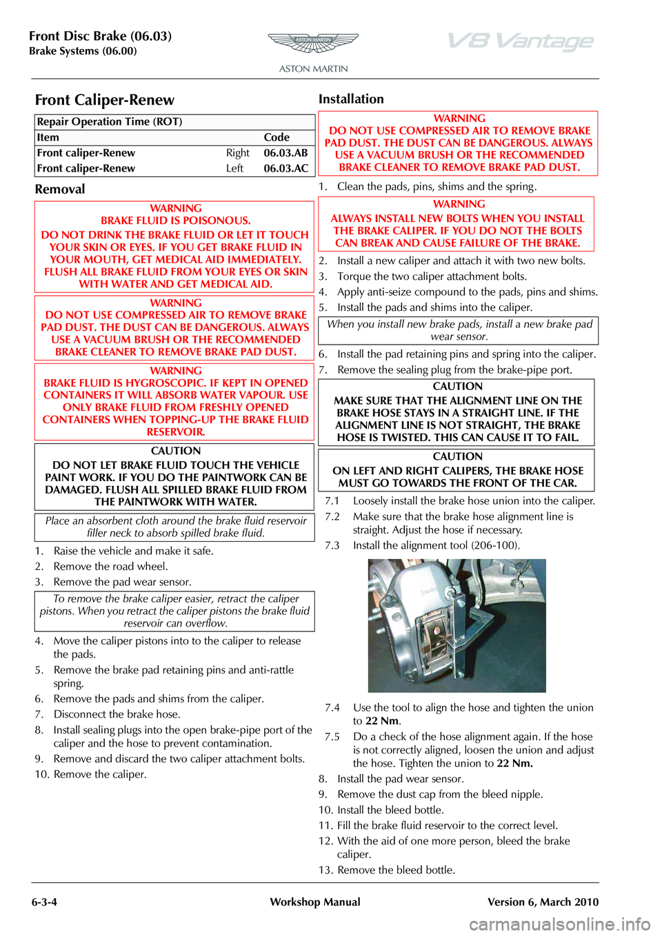
7.3 Install the alignment tool (206-100).
7.4 Use the tool to align the hose and tighten the union to 22 Nm .
7.5 Do a check of the hose alignment again. If the hose is not correctly aligned, loosen the union and adjust
the hose. Tighten the union to 22 Nm.
8. Install the pad wear sensor.
9. Remove the dust cap from the bleed nipple.
10. Install the bleed bottle.
11. Fill the brake fluid reservoir to the correct level.
12. With the aid of one more person, bleed the brake caliper.
13. Remove the bleed bottle.
Repair Operation Time (ROT)WAR NI NG
DO NOT USE COMPRESSED AIR TO REMOVE BRAKE
PAD DUST. THE DUST CAN BE DANGEROUS. ALWAYS USE A VACUUM BRUSH OR THE RECOMMENDED BRAKE CLEANER TO REMOVE BRAKE PAD DUST.
WA R N I N G
ALWAYS INSTALL NEW BOLTS WHEN YOU INSTALL THE BRAKE CALIPER. IF YOU DO NOT THE BOLTS
CAN BREAK AND CAUSE FAILURE OF THE BRAKE.
When you install new brake pads, install a new brake pad wear sensor.
CAUTION
MAKE SURE THAT THE ALIGNMENT LINE ON THE BRAKE HOSE STAYS IN A STRAIGHT LINE. IF THE
ALIGNMENT LINE IS NOT STRAIGHT, THE BRAKE HOSE IS TWISTED. THIS CAN CAUSE IT TO FAIL.
CAUTION
ON LEFT AND RIGHT CALIPERS, THE BRAKE HOSE MUST GO TOWARDS THE FRONT OF THE CAR.
Page 488 of 947
Brake Actuation System (06.06)
Brake System (06.00)
6-6-2 Workshop Manual May 2007
Maintenance
Pedal Box Assembly - Renew
1. Remove front seat (see Workshop Manual procedure 01.10.AB Seat Assembly - Front - RH - Remove for
Access and Refit).
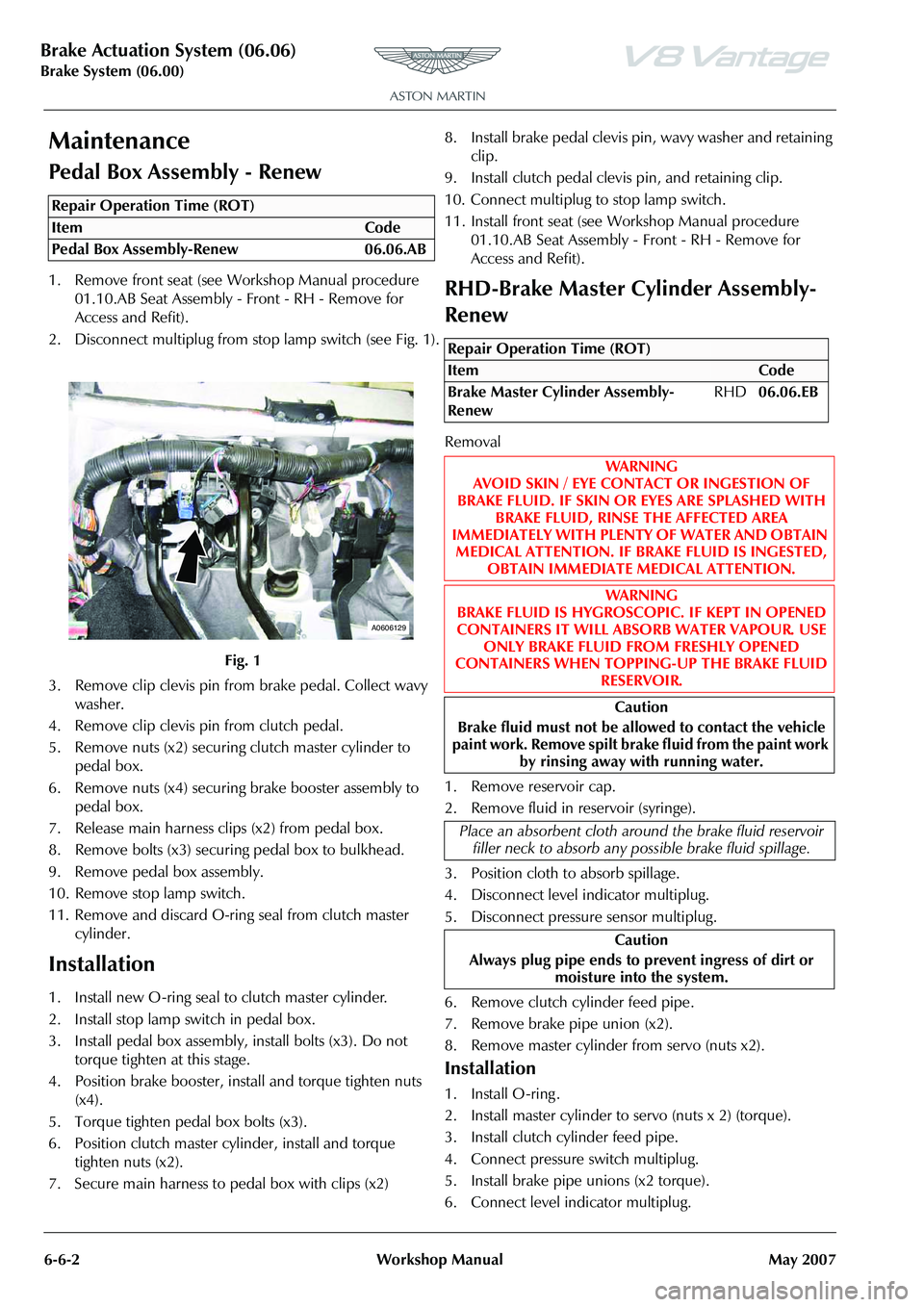
2. Disconnect multiplug from stop lamp switch (see Fig. 1).
3. Remove clip clevis pin from brake pedal. Collect wavy washer.
4. Remove clip clevis pin from clutch pedal.
5. Remove nuts (x2) securing clutch master cylinder to
pedal box.
6. Remove nuts (x4) securing brake booster assembly to
pedal box.
7. Release main harness clips (x2) from pedal box.
8. Remove bolts (x3) securing pedal box to bulkhead.
9. Remove pedal box assembly.
10. Remove stop lamp switch.
11. Remove and discard O-ring seal from clutch master cylinder.
Installation
1. Install new O-ring seal to clutch master cylinder.
2. Install stop lamp switch in pedal box.
3. Install pedal box assembly, install bolts (x3). Do not torque tighten at this stage.
4. Position brake booster, install and torque tighten nuts (x4).
5. Torque tighten pedal box bolts (x3).
6. Position clutch master cy linder, install and torque
tighten nuts (x2).
7. Secure main harness to pedal box with clips (x2) 8. Install brake pedal clevis pin, wavy washer and retaining
clip.
9. Install clutch pedal clevis pin, and retaining clip.
10. Connect multiplug to stop lamp switch.
11. Install front seat (see Workshop Manual procedure
01.10.AB Seat Assembly - Front - RH - Remove for
Access and Refit).
RHD-Brake Master Cylinder Assembly-
Renew
Removal
1. Remove reservoir cap.
2. Remove fluid in reservoir (syringe).
3. Position cloth to absorb spillage.
4. Disconnect level indicator multiplug.
5. Disconnect pressure sensor multiplug.
6. Remove clutch cylinder feed pipe.
7. Remove brake pipe union (x2).
8. Remove master cylinder from servo (nuts x2).
Installation
1. Install O-ring .
2. Install master cylinder to servo (nuts x 2) (torque).
3. Install clutch cylinder feed pipe.
4. Connect pressure switch multiplug.
5. Install brake pipe unions (x2 torque).
6. Connect level indicator multiplug.
Repair Operation Time (ROT)
A0606129
Repair Operation Time (ROT)
ItemCode
Brake Master Cylinder Assembly-
Renew RHD
06.06.EB
WAR NI NG
AVOID SKIN / EYE CONTACT OR INGESTION OF
BRAKE FLUID. IF SKIN OR EYES ARE SPLASHED WITH BRAKE FLUID, RINSE THE AFFECTED AREA
IMMEDIATELY WITH PLENTY OF WATER AND OBTAIN MEDICAL ATTENTION. IF BR AKE FLUID IS INGESTED,
OBTAIN IMMEDIATE MEDICAL ATTENTION.
WAR NI NG
BRAKE FLUID IS HYGROSCOPIC. IF KEPT IN OPENED
CONTAINERS IT WILL ABSORB WATER VAPOUR. USE ONLY BRAKE FLUID FROM FRESHLY OPENED
CONTAINERS WHEN TOPPING-UP THE BRAKE FLUID
RESERVOIR.
Caution
Brake fluid must not be allowed to contact the vehicle
paint work. Remove spilt brake fluid from the paint work
by rinsing away with running water.
Place an absorbent cloth around the brake fluid reservoir filler neck to absorb any possible brake fluid spillage.
Caution
Always plug pipe ends to prevent ingress of dirt or
moisture into the system.
Page 489 of 947

Brake Actuation System (06.06)
Brake System (06.00)
May 2007 Workshop Manual 6-6-3
7. Fill reservoir.
8. Bleed Brakes (see Workshop Manual procedure 06.06.AD Pad Kit - Manual Brake and Clutch Pedal -
Renew).
LHD-Brake Master Cylinder Assembly-
Renew
Removal
1. Remove corner cross brace.
2. Move expansion tank aside for access (bolt x1, nut x1, hose clips x2, multiplug x1).
3. Disconnect clutch reservoir feed pipe.
4. Disconnect multiplugs (x2).
5. Disconnect brake pipes from master cylinder (move aside).
6. Remove reservoir holding screw for access to master cylinder retaining nut.
7. Remove master cylinder from booster (nuts x2).
Installation
1. On new master cylinder - Remove reservoir holding screw for access to master cylinder retaining nut.
2. Install master cylinder to booster (nuts x2).
3. Install reservoir holding screw for access to master cylinder retaining nut.
4. Connect brake pipes to master cylinder.
5. Connect clutch reservoir feed pipe. 6. Connect multiplugs (x2).
7. Install expansion tank aside (bolt x1, nut x1, hose clips
x2, multiplug x1).
8. Install corner cross brace (torque) (only fully tighten
when vehicle on level floor).
9. Bleed Brakes (see Workshop Manual procedure 06.06.AD Pad Kit - Manual Brake and Clutch Pedal -
Renew).
10. Top-up coolant.
Clutch Master Cylinder Assembly-Renew
Removal
1. Move drivers seat fully rearward.
2. Remove clevis pin and clip.
3. Remove cylinder securing nuts (x2).
4. Remove fluid (syringe) from brake master cylinder to
below clutch level.
5. Remove corner cross brace.
6. Move expansion tank aside for access (bolt x1, nut x1, hose clips x2, multiplug x1).
7. Disconnect clutch reservoir feed pipe.
8. Disconnect clutch pipe quick fit (pull clip back) and move aside.
9. Remove cylinder assembly.
10. Remove and discard O-ring seal from master cylinder.
11. Split components
12. Remove pipe from cy linder (mark position).
Repair Operation Time (ROT)
Repair Operation Time (ROT)
Page 519 of 947

Manual Transmission (07.03)
Transmission (07.00)
Issue 5, January 2010 Workshop Manual 7-3-3
4. Remove the four bolts that attach the cross-brace to the rear subframe.
Figure 2
5. Remove the cross brace.
6. Remove the four bolts that attach the exhaust centre pipe to the rear silencer.
7. Loosen the two clamps that attach the exhaust centre pipe to the catalytic converters.
8. Move the clamps along the exhaust pipes.
9. Remove the four bolts that attach the exhaust centre pipe to the exhaust front mount.
10. Remove the exhaust centre pipe.
11. Remove the exhaust front mount.
12. Remove the four bolts that attach the floor heat shield to the body.
13. Remove the floor heatshield.
14. Remove the eight screws that attach the tunnel reinforcement plate to the body.
Figure 3
15. Remove the tunnel reinforcement plate. 16. Remove the nut that attaches the ground cable to the
body.
Figure 4
17. Move the ground cable away.
18. Put marks on the driveshaft to transaxle flanges to help align during installation.
19. Remove and discard the six bolts that attach the right
side driveshaft to the transaxle. Collect and keep the
bolt plates.
Figure 5
20. Remove and discard the six bolts that attach the left side driveshaft to the transaxle. Collect and keep the bolt
plates.
WARNING
GET THE AID OF ONE MORE PERSON WHEN YOU REMOVE THE EXHAUST CENTRE PIPE.
THE CENTRE EXHAUST PIPE IS HEAVY
Note: If necessary, turn the dr iveshaft to get access to the
six bolts.
Note: If necessary, turn the dr iveshaft to get access to the
six bolts.
Page 521 of 947

Manual Transmission (07.03)
Transmission (07.00)
Issue 5, January 2010 Workshop Manual 7-3-5
31. Put a transmission jack be low the transaxle (refer to
Figure 12).
Figure 12
32. Adjust the height of the tran smission jack until it holds
the transaxle.
33. Remove and discard the four bolts that attach the right
side transaxle mount bracket to the transaxle. (see
Figure 13).
Figure 13
34. Remove and discard the four bolts that attach the left side transaxle mount bracket to the transaxle.
Figure 14
35. Remove the transaxle mount assemblies.
Figure 15
36. Use an applicable strap to attach the transaxle to the transmission jack.
37. Lower the transaxle on the transmission jack by approximately 420 mm.
38. Release the wiring harness for the reverse lamp switch from the clip.
39. Release the electrical connector for the reverse lamp switch from the mount.
Figure 16
40. Disconnect the electrical connector from the reverse lamp switch.
Page 523 of 947

Manual Transmission (07.03)
Transmission (07.00)
Issue 5, January 2010 Workshop Manual 7-3-7
7. Connect the electrical connector to the reverse lamp switch.
8. Install the electrical connector for the reverse lamp switch into the mount.
9. Install the wiring harness for the reverse lamp switch to the clip.
10. Adjust the height of the transmission jack to lift the transaxle into the correct position.
11. Remove the strap from the transaxle and the transmission jack.
12. Install the transaxle mount assemblies.
Figure 21
13. Install and torque the four bolts that attach the left side transaxle mount bracket to the transaxle.
Figure 22
14. Install and torque the four bolts that attach the right side transaxle mount bracket to the transaxle.
Figure 23
15. Lower the transmission jack to align the transaxle mounts to the rear subframe.
16. Move the transmission jack away from the vehicle.
17. Install and tighten the nut that attaches the left side transaxle mount to the rear subframe.
18. Install and tighten the nut that attaches the right side transaxle mount to the rear subframe.
19. Remove and the sealing plugs from the transaxle and the breather pipe.
20. Connect breather pipe to the transaxle.
21. Remove and discard the sealing plugs from the oil cooler matrix and the pipes.
22. Connect and tighten the pipes to the oil cooler matrix.
23. Put the driveshafts into position on the transaxle shaft flanges. Align the marks on the flanges that you made
during removal.
24. Install and torque the six new bolts that attach the left side driveshaft flange to the transaxle flange. If
necessary, turn the driveshaft to get access to all of the
bolts.
25. Install and torque the six new bolts that attach the right side driveshaft flange to the transaxle flange. If
necessary, turn the driveshaft to get access to all of the
bolts.
26. Put the ground cable into position.
27. Install and tighten the nut that attaches the ground cable to the body.
28. Install the tunnel reinforcement plate.
29. Install and torque the eight bolts that attach the tunnel reinforcement plate to the body.
30. Install floor heatshield.
31. Install and tighten the four bolts that attach the floor heat shield to the body.
Note: Put the three driveshaft bolt plates in position when
you install the bolts in the step that follows.
Note: Put the three driveshaft bolt plates in position when
you install the bolts in the step that follows.