height ASTON MARTIN V8 VANTAGE 2010 Workshop Manual
[x] Cancel search | Manufacturer: ASTON MARTIN, Model Year: 2010, Model line: V8 VANTAGE, Model: ASTON MARTIN V8 VANTAGE 2010Pages: 947, PDF Size: 43.21 MB
Page 13 of 947
Issue 5, January 2010 Workshop Manual 1-1-1
Body System (01.00)
Contents
Body Structure (01.01)........................................... 1-1-4Overview ................................................................ 1-4
Specifications.......................................................... 1-4
Maintenance ........................................................... 1-5Right Side Front Crush Bar for the Body
Reinforcement - Remove and Install ....................... 1-5
Left Side Front Crush Bar for the Body
Reinforcement - Remove and Install ....................... 1-5
Front Crush Brace - Remove and Install .................. 1-5
Front End (01.02) ................................................... 1-2-1 Front Wings ............................................................ 2-1Specifications ......................................................... 2-1
Maintenance ........................................................... 2-1 Radiator Closing Panel - Remove and Install ........... 2-1
Centre Undertray - Remove and Install
(Roadster Only) ..................................................... 2-1
Front Undertray-Remove and Install ....................... 2-2
Rear Undertray - Renew (Coupe only).................... 2-2
Rear Undertray - Renew (Roadster only) ................ 2-2
Install ..................................................................... 2-2.............................................................................. 2-2
Undertray, Vehicle Set - Renew ............................. 2-2
RH/LH Front Wheel Arch Liner - Renew ................ 2-2
RH/LH Rear Wheel Arch Liner - Renew ................. 2-3
RH Front Wing Panel Assembly - Renew ................ 2-4
LH Front Wing Panel Assembly - Renew ................ 2-6
Body Closures (01.03) ........................................... 1-3-1 Specifications.......................................................... 3-1Doors .................................................................... 3-1
Tailgate .................................................................. 3-1
Bonnet................................................................... 3-2
Maintenance ........................................................... 3-2 LH/RH Door Assembly-Renew ............................... 3-2
RH/LH Door Assembly-Remove/Refit ..................... 3-6
Front Door Hinge (One Side) - Renew ................... 3-6
Front Door Check Arm Assembly - Renew ............. 3-7
Boot Lid Assembly - Renew (Roadster Only) ........... 3-7
Boot Lid Hinge Assembly (Pair) - Renew
(Roadster Only) .................................................... 3-10
Boot Gas Strut (Pair) - Renew (Roadster Only) ...... 3-11
Boot Lid Striker Assembly - Renew
(Roadster Only) .................................................... 3-11
Exterior Boot Lid Switch Release - Renew
(Roadster Only) .................................................... 3-12
Tailgate Assembly - Renew ................................... 3-12
Tailgate Hinge Assembly (Pair) - Renew ................ 3-13
Hood Assembly - Renew ...................................... 3-14
Hood Hinge Assembly (Vehicle Set) - Renew ....... 3-14
Interior Trim (01.05).............................................. 1-4-1 Maintenance ........................................................... 4-1Rear Centre Console - Renew ................................ 4-1
Headlining - Renew (Roadster Only) ...................... 4-1
Header Panel As sembly - Renew
(Excluding Roadster)............................................... 4-6 Header Panel Assembly - Renew (Roadster Only)... 4-7
Front Header Console Assembly - Renew............... 4-7
RH/LH Upper Rear Pillar Panel Assembly
- Renew ................................................................. 4-8
RH Sun Visor - Renew ........................................... 4-8
LH Sun Visor - Renew ............................................ 4-8
Door Trimboard Assembly - Renew ....................... 4-9
Door Trimboard Assembly
- Remove for Access/Refit ...................................... 4-9
Lower Quarter Trim Panel Assembly - Renew
(Roadster Only)...................................................... 4-9
Side Carpet Kit (RHD) - Renew ............................ 4-11
Side Carpet Kit (LHD) - Renew ............................ 4-12
Top Rear Console Fini
sher Panel Assembly
- Renew (Roadster Only) ...................................... 4-14
RH/LH Bodyside Rear Trim Panel Assembly
- Renew (Roadster Only) ...................................... 4-14
Tonneau to Body Weatherstrip Assembly
- Renew (Roadster Only) ...................................... 4-15
Door Trim Weather Strip Assembly - Renew
(Roadster Only).................................................... 4-16
Exterior Trim (01.08) ............................................. 1-5-1 Maintenance ........................................................... 5-1RH/LH Applique Sill - Renew ................................. 5-1
RH Wing Side Strake - Renew................................ 5-2
LH Wing Side Strake - Renew ................................ 5-2
Channel Assembly Divider Bar - Renew ................. 5-2
Windshield Header Finisher - Renew
(Roadster Only)...................................................... 5-3
Mirrors (01.09) ...................................................... 1-6-1 Specifications ......................................................... 6-1
Maintenance ........................................................... 6-1RH Door Mirror Assembly - Renew ........................ 6-1
LH Door Mirror Assembly - Renew ........................ 6-1
Seating (01.10)....................................................... 1-7-1 Description ............................................................. 7-1Heated Seats ......................................................... 7-1
Specifications ........................................................ 7-1
Maintenance ........................................................... 7-1 RH/LH Front Seat - Remove and Install .................. 7-1
Front Seat Squab Cover Assembly
(Each, Pre-08MY) - Remove and Install .................. 7-1
Front Seat Squab Cover Assembly
(Each, from 08MY) - Remove and Install................. 7-3
Front Seat Cushion Cover Assembly (Each)
- Renew ................................................................. 7-3
6-Way Height Adjuster (Inc. Motors) - Renew ........ 7-4
Squab Motor Kit - Renew....................................... 7-6
Lumbar Support Kit - Renew .................................. 7-7
Side Airbag - Renew .............................................. 7-8
Front Seat Buckle Assembly - Renew...................... 7-9
Valance Heater and Lumbar Switch Assembly
- Renew ................................................................. 7-9
Seat Harness Kit - Renew ..................................... 7-10
Page 39 of 947
Body Closures (01.03)
Body System (01.00)
May 2007 Workshop Manual 1-3-13
3. Remove LH quarter upper trim panel (see Workshop
Manual procedure 01.05.CY Moulding Assembly -
Quarter Trim Upper - LH - Renew).
4. Remove rear header trim panel (see Workshop Manual procedure 01.05.BK Panel Assembly - Rear Header -
Renew).
5. Disconnect LH and RH tailgate harnesses in cabin
6. Remove LH and RH harness grommets from body.
7. Remove tailgate trim panel (see Workshop Manual procedure 01.05.EF Trim - Tailgate Lid Assembly -
Renew).
8. Disconnect GPS antenna mult iplug, remove bolts (x3),
remove GPS antenna.
9. Disconnect multiplug form central high stop lamp, remove nuts (x2), remove central high stop lamp.
10. Disconnect multiplug from tailgate release switch,
remove nuts (x2), remove tailgate release switch.
11. Remove tailgate buffer stops (x2).
12. Install protection between tailgate corners and bodywork.
13. Release clips, disconnect gas struts (x2) from tailgate.
14. With assistance, remove bolt s (x4) securing tailgate to
hinges, remove tailgate assembly.
Installation
1. With assistance, install and align tailgate to hinges, install bolts (x4). Do not torque tighten at this stage.
2. Adjust alignment of tailgate and torque tighten hinge bolts.
3. Connect gas struts to tailgate and secure with clips.
4. Install tailgate buffers and adjust height as necessary
5. Install tailgate release switch, install and tighten nuts (x2), connect multiplug.
6. Install central high level st op lamp assembly, install and
tighten nuts (x2), connect multiplug.
7. Install GPS antenna, install and tighten bolts (x3), connect multiplug.
8. Install tailgate trim panel (see Workshop Manual procedure 01.05.EF Trim - Tailgate Lid Assembly -
Renew).
9. Install rear header trim panel (see Workshop Manual procedure 01.05.BK Panel Assembly - Rear Header -
Renew).
10. Install LH upper quarter trim panel (see Workshop Manual procedure 01.05.CY Moulding Assembly -
Quarter Trim Upper - LH - Renew).
11. Install RH upper quarter trim panel (see Workshop Manual procedure 01.05.CX Moulding Assembly -
Quarter Trim Upper - RH - Renew).
12. Remove protection from tailgate and body.
13. Battery isolation switch ‘ON’.
Tailgate Hinge Assembly (Pair) - Renew
Removal
1. Protect bodywork.
2. Mark position of hinges.
3. With assistance support and hold tailgate.
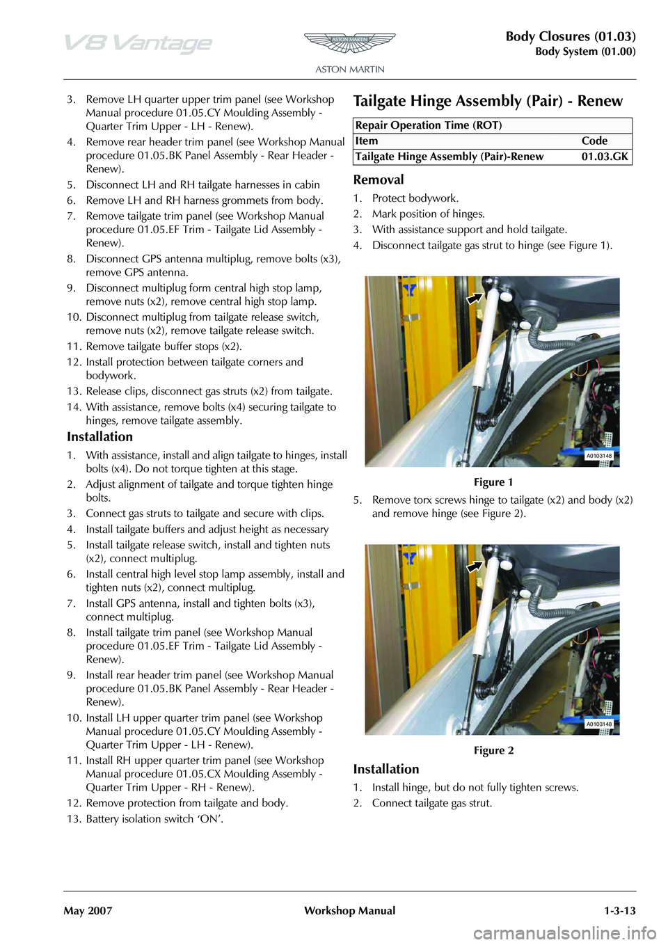
4. Disconnect tailgate gas strut to hinge (see Figure 1).
5. Remove torx screws hinge to tailgate (x2) and body (x2) and remove hinge (see Figure 2).
Installation
1. Install hinge, but do not fully tighten screws.
2. Connect tailgate gas strut.
Repair Operation Time (ROT)
A0103148
A0103148
Page 70 of 947
Seating (01.10)
Body System (01.00)1-7-4 Workshop Manual Issue 4, November 2008
Removal
1. Remove 6 way height adjust er (see Workshop Manual
procedure 01.10.AE 6 Way Height Adjuster - Including
Motors - Renew).
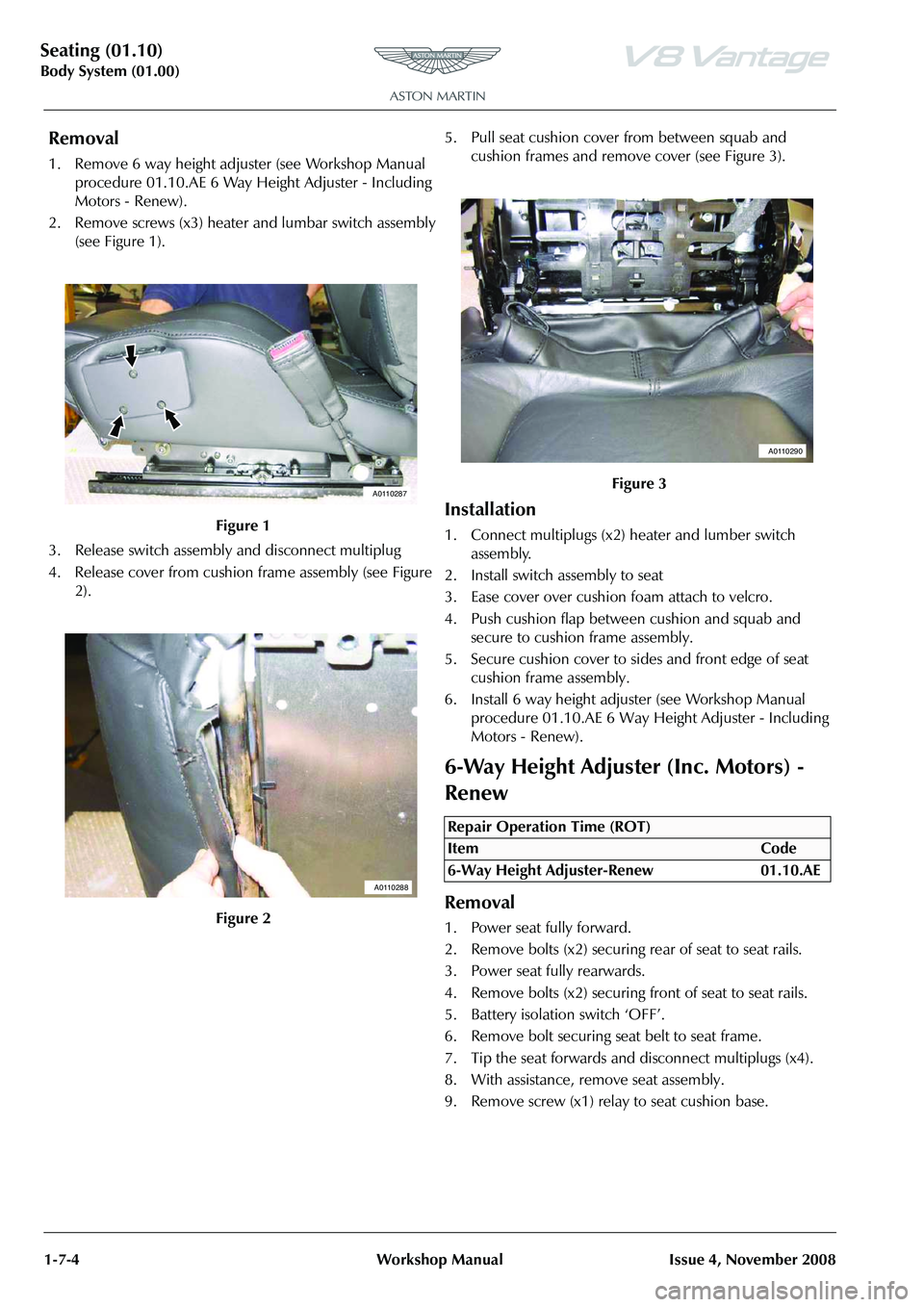
2. Remove screws (x3) heater and lumbar switch assembly
(see Figure 1).
3. Release switch assembly and disconnect multiplug
4. Release cover from cushion frame assembly (see Figure 2). 5. Pull seat cushion cover from between squab and
cushion frames and remove cover (see Figure 3).
Installation
1. Connect multiplugs (x2) heater and lumber switch assembly.
2. Install switch assembly to seat
3. Ease cover over cushion foam attach to velcro.
4. Push cushion flap between cushion and squab and secure to cushion frame assembly.
5. Secure cushion cover to sides and front edge of seat cushion frame assembly.
6. Install 6 way height adjust er (see Workshop Manual
procedure 01.10.AE 6 Way He ight Adjuster - Including
Motors - Renew).
6-Way Height Adjuster (Inc. Motors) -
Renew
Removal
1. Power seat fully forward.
2. Remove bolts (x2) securing rear of seat to seat rails.
3. Power seat fully rearwards.
4. Remove bolts (x2) securing front of seat to seat rails.
5. Battery isolation switch ‘OFF’.
6. Remove bolt securing seat belt to seat frame.
7. Tip the seat forwards and disconnect multiplugs (x4).
8. With assistance, remove seat assembly.
9. Remove screw (x1) relay to seat cushion base.
Figure 1
Figure 2
A0110287
A0110288
Figure 3
Repair Operation Time (ROT)
ItemCode
6-Way Height Adjuster-Renew 01.10.AE
A0110290
Page 71 of 947
Seating (01.10)
Body System (01.00)
Issue 4, November 2008 Workshop Manual 1-7-5
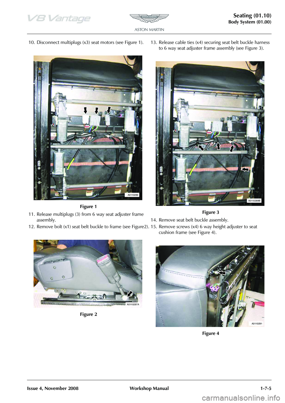
10. Disconnect multiplugs (x3) seat motors (see Figure 1).
11. Release multiplugs (3) from 6 way seat adjuster frame
assembly.
12. Remove bolt (x1) seat belt buckle to frame (see Figure2). 13. Release cable ties (x4) securing seat belt buckle harness
to 6 way seat adjuster fram e assembly (see Figure 3).
14. Remove seat belt buckle assembly.
15. Remove screws (x4) 6 way height adjuster to seat cushion frame (see Figure 4).
Figure 1
Figure 2
A0110289
A0110287A
Figure 3
Figure 4
A0110289B
A0110291
Page 72 of 947
Seating (01.10)
Body System (01.00)1-7-6 Workshop Manual Issue 4, November 2008
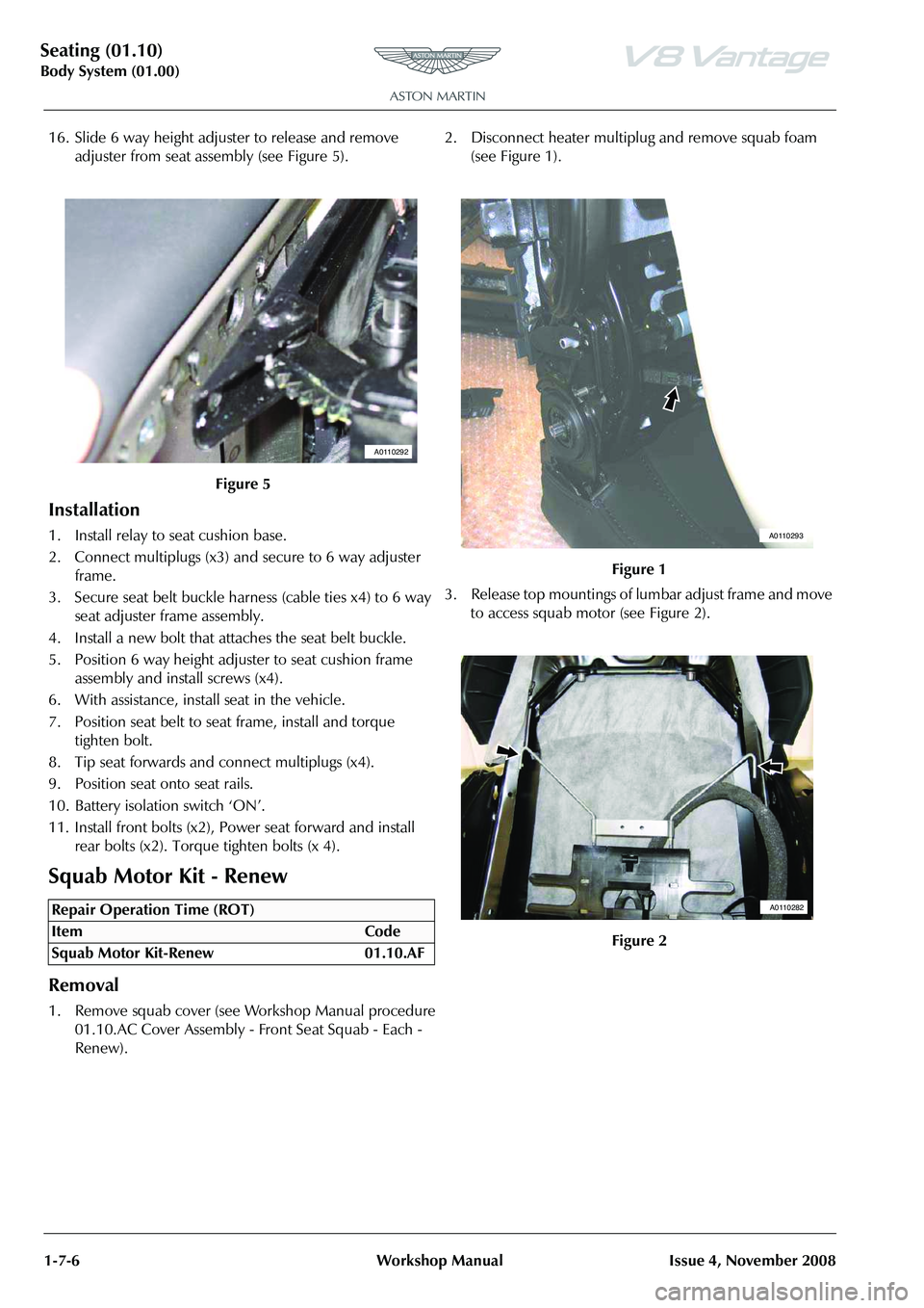
16. Slide 6 way height adjuster to release and remove adjuster from seat assembly (see Figure 5).
Installation
1. Install relay to seat cushion base.
2. Connect multiplugs (x3) and secure to 6 way adjuster frame.
3. Secure seat belt buckle harness (cable ties x4) to 6 way seat adjuster frame assembly.
4. Install a new bolt that attaches the seat belt buckle.
5. Position 6 way height adju ster to seat cushion frame
assembly and install screws (x4).
6. With assistance, install seat in the vehicle.
7. Position seat belt to seat frame, install and torque tighten bolt.
8. Tip seat forwards and connect multiplugs (x4).
9. Position seat onto seat rails.
10. Battery isolation switch ‘ON’.
11. Install front bolts (x2), Power seat forward and install rear bolts (x2). Torque tighten bolts (x 4).
Squab Motor Kit - Renew
Removal
1. Remove squab cover (see Workshop Manual procedure 01.10.AC Cover Assembly - Front Seat Squab - Each -
Renew). 2. Disconnect heater multiplug and remove squab foam
(see Figure 1).
3. Release top mountings of lumbar adjust frame and move to access squab motor (see Figure 2).
Figure 5
Repair Operation Time (ROT)
A0110292
Figure 1
Figure 2
A0110293
A0110282
Page 76 of 947
Seating (01.10)
Body System (01.00)1-7-10 Workshop Manual Issue 4, November 2008
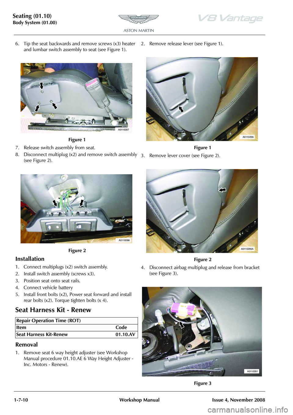
6. Tip the seat backwards and remove screws (x3) heater and lumbar switch assembly to seat (see Figure 1).
7. Release switch assembly from seat.
8. Disconnect multiplug (x2) and remove switch assembly (see Figure 2).
Installation
1. Connect multiplugs (x2) switch assembly.
2. Install switch assembly (screws x3).
3. Position seat onto seat rails.
4. Connect vehicle battery
5. Install front bolts (x2), Power seat forward and install rear bolts (x2). Torque tighten bolts (x 4).
Seat Harness Kit - Renew
Removal
1. Remove seat 6 way height adjuster (see Workshop Manual procedure 01.10.AE 6 Way Height Adjuster -
Inc. Motors - Renew). 2. Remove release lever (see Figure 1).
3. Remove lever cover (see Figure 2).
4. Disconnect airbag multiplu
g and release from bracket
(see Figure 3).
Figure 1
Figure 2
Repair Operation Time (ROT)
A0110287
A0110286
Figure 1
Figure 2
Figure 3
A0110296
A0110296A
A0110281
Page 79 of 947
Seating (01.10)
Body System (01.00)
Issue 4, November 2008 Workshop Manual 1-7-13
11. Secure cover to bottom of seat back shell.
12. Secure cover to seat back shell (studs and velcro).
13. Install airbag module (bolt x1) (torque).
14. Install multiplug bracket fixing.
15. Connect airbag multiplu g and secure to bracket.
16. Install lever cover.
17. Install release lever.
18. Install seat 6 way height adjuster (see Workshop Manual procedure 01.10.AE 6 Way Height Adjuster - Inc.
Motors - Renew).
RH/LH Seat Switchpack Assembly -
Renew
Removal
1. Remove instrument panel bezel assembly (see Workshop Manual procedure 01.12.AV Bezel Assembly
- Instrument Panel - Remove for Access and Refit).
2. Remove console panel assembly (see Workshop Manual procedure 01.12.DB Panel Assembly Console - Renew).
3. Remove instrument cluster hood (6 clips)
4. Remove passenger upper ou ter panel assembly (see
Workshop Manual procedure 01.12.AE Panel Assembly
- IP - Upper - Passenger - Renew).
5. Remove passenger panel assembly (4 clips and 4 screws)
6. Remove driver's upper inner panel assembly (5 clips)
7. Remove driver's upper outer panel assembly (4 clips)
8. Remove driver's panel assembly (4 clips and 3 screws)
9. Remove receiver and audio media system panel screws (x4), disconnect multiplugs (x12).
10. Pull back carpet and disconnect seat adjust switch multiplugs (x6), release harness clip (x2)
11. Remove instrument centre panel assembly
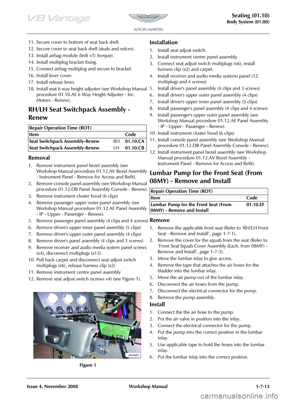
12. Remove seat adjust switch (screws x4) (see Figure 1).
Installation
1. Install seat adjust switch.
2. Install instrument centre panel assembly
3. Connect seat adjust switch multiplugs (x6), install
harness clip (x2) and carpet.
4. Install receiver and audio media systems panel (12 multiplugs and 4 screws)
5. Install driver's panel asse mbly (4 clips and 3 screws)
6. Install driver's upper oute r panel assembly (4 clips)
7. Install driver's upper inne r panel assembly (5 clips)
8. Install passenger's panel assembly (4 clips and 4 screws)
9. Install passenger's upper outer panel assembly (see
Workshop Manual procedure 01.12.AE Panel Assembly
- IP - Upper - Passenger - Renew).
10. Install instrument cluster hood (6 clips)
11. Install console panel assemb ly (see Workshop Manual
procedure 01.12.DB Panel Assembly Console - Renew).
12. Install instrument panel be zel assembly (see Workshop
Manual procedure 01.12.AV Bezel Assembly -
Instrument Panel - Remove for Access and Refit).
Lumbar Pump for the Front Seat (From
08MY) - Remove and Install
Remove
1. Remove the applicable front seat (Refer to ’RH/LH Front Seat - Remove and Install’, page 1-7-1).
2. Remove the cover for the squab from the seat (Refer to ’Front Seat Squab Cover Assembly (Each, from 08MY) -
Remove and Install’, page 1-7-3).
3. Move the lumbar inlay to give access.
4. Remove the tape that attaches the air hoses for the bladder into the lumbar inlay.
5. Move the air pump out of the lumbar inlay.
6. Disconnect the air hoses from the pump.
7. Disconnect the electrical connector for the pump.
8. Remove the pump assembly.
Install
1. Connect the the air hose to the pump.
2. Put the air valve in position into the inlay.
3. Connect the electrical connector for the pump.
4. Put the pump into the correct position in the lumbar inlay.
5. Use applicable tape to hold the hoses into the lumbar inlay.
6. Put the lumbar inlay into the correct position.
Repair Operation Time (ROT)
A0110231
Repair Operation Time (ROT)
Page 224 of 947
Subframes (02.03)
Frame and Mounting (02.00)
2-1-2 Workshop Manual May 2007
Frame and Mounting (02.00)
Subframes (02.03)
Specifications
Maintenance
Front Subframe-Renew
Removal
1. Switch battery isolation switch ‘OFF’.
2. Raise vehicle on ramp.
3. Remove RH wheel arch liner (see Workshop Manual procedure 01.02.GB Wheel Arch Liner - Front - RH -
Renew).
4. Remove LH wheel arch liner (see Workshop Manual procedure 01.02.FB Wheel Arch Liner - Front - LH -
Renew)
5. Remove road wheel/s.
6. Remove front spring/damper assemblies (see Workshop Manual procedure 04.03.AA Spring and Damper
Assembly - Front Pair - Renew).
7. Remove nuts (x2) from track rod ends to vertical link.
8. Using special tool 204-523, release track rod end from vertical link.
9. Disconnect ABS sensor multiplugs then release sensor harness clips (x6) from upper suspension arm and
vertical link.
10. Disconnect brake pad wear sensor multiplug then release sensor harness clips (x2) from upper suspension
arms. 11. Remove Allen bolts (x4) from brake callipers to vertical
link and tie callipers aside.
12. Remove Torx screws (x4) from brake disc to hub and remove brake disc.
13. Remove anti-roll bar links nuts (x2) and washers (x2).
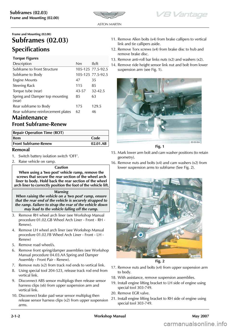
14. Remove ride height sensor link nut and bolt from lower
suspension arm (see Fig. 1).
15. Mark lower arm bolt and cam washer positions (to retain
geometry).
16. Remove nuts and bolts (x4) and cam washers (x2) from lower suspension arms to subframe (See Fig. 2).
17. Remove nuts and bolts (x4) from upper suspension arm to body.
18. With assistance, remove suspension assemblies.
19. Install engine lifting bracket to LH side of engine using special tool 303-749.
20. Remove EGR valve.
21. Install engine lifting bracket to RH side of engine using special tool 303-749.
Torque Figures
DescriptionNmIb/ft
Subframe to Front Structure 105-125 77.5-92.5
Subframe to Body 105-125 77.5-92.5
Engine Mounts 47 35
Steering Rack 115 85
Torque tube (rear) 43-57 32-42.5
Spring and Damper top mounting
(rear) 85 63
Rear subframe to Body 175 129.5
Rear subframe reinforcement plates 62 46
Repair Operation Time (ROT)
Warning
When raising the vehicle on a 'two post' ramp, ensure
that the rear end of the vehi cle is securely strapped to
the ramp. Failure to strap th e rear of the vehicle down
may lead to the vehicl e falling off the ramp.
Fig. 1
Fig. 2
Page 225 of 947
Subframes (02.03)
Frame and Mounting (02.00)
May 2007 Workshop Manual 2-1-3
22. Install cross brace support brackets 303-021-02 (x6).
23. Support engine using special tool SPX M553D.
24. Remove undertray (see Workshop Manual procedure 01.02.NB Undertray - Front - Renew).
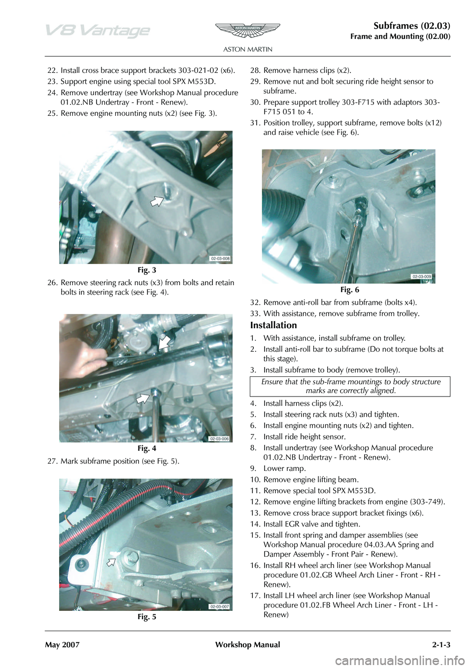
25. Remove engine mounting nuts (x2) (see Fig. 3).
26. Remove steering rack nuts (x3) from bolts and retain bolts in steering rack (see Fig. 4).
27. Mark subframe position (see Fig. 5). 28. Remove harness clips (x2).
29. Remove nut and bolt securi
ng ride height sensor to
subframe.
30. Prepare support trolley 30 3-F715 with adaptors 303-
F715 051 to 4.
31. Position trolley, support subframe, remove bolts (x12)
and raise vehicle (see Fig. 6).
32. Remove anti-roll bar from subframe (bolts x4).
33. With assistance, remove subframe from trolley.
Installation
1. With assistance, install subframe on trolley.
2. Install anti-roll bar to subframe (Do not torque bolts at this stage).
3. Install subframe to body (remove trolley).
4. Install harness clips (x2).
5. Install steering rack nuts (x3) and tighten.
6. Install engine mounting nuts (x2) and tighten.
7. Install ride height sensor.
8. Install undertray (see Workshop Manual procedure 01.02.NB Undertray - Front - Renew).
9. Lower ramp.
10. Remove engine lifting beam.
11. Remove special tool SPX M553D.
12. Remove engine lifting brack ets from engine (303-749).
13. Remove cross brace suppo rt bracket fixings (x6).
14. Install EGR valve and tighten.
15. Install front spring and damper assemblies (see Workshop Manual procedure 04.03.AA Spring and
Damper Assembly - Front Pair - Renew).
16. Install RH wheel arch li ner (see Workshop Manual
procedure 01.02.GB Wheel Arch Liner - Front - RH -
Renew).
17. Install LH wheel arch liner (see Workshop Manual procedure 01.02.FB Wheel Arch Liner - Front - LH -
Renew)
Fig. 3
Fig. 4
Fig. 5
Fig. 6
Ensure that the sub-frame mo untings to body structure
marks are correctly aligned.
Page 226 of 947
Subframes (02.03)
Frame and Mounting (02.00)
2-1-4 Workshop Manual May 2007
18. With assistance, install suspension assemblies, lower suspension arms, nuts and bolts and cam washers
(x2)(do not torque tighten at this stage).
19. Install upper suspension arms to body (do not torque tighten at this stage).
20. Install ride height sensor link to lower suspension arm and tighten.
21. Install and tighten nuts (x2) from track rod ends to vertical link.
22. Install anti-roll bar to links nuts and washers (x2) and tighten.
23. Clean and install brake discs and install and tighten Torx screws (x4)).
24. Install brake callipers and to rque tighten Allen bolts (x4).
25. Connect brake pad wear sensor multiplug and secure harness clips (x4) in upper suspension arms.
26. Connect ABS sensor multiplugs and secure harness clips (x6) in upper suspension arms and vertical links.
27. Install road wheel/s.
28. Lower vehicle on ramp.
29. Torque tighten suspension nuts and bolts.
30. Battery isolation switch ‘ON’.
31. 4 wheel alignment check and adjust (See Workshop Manual procedure 04.00.AD 4 Wheel Alignment -
Check and Adjust).
Front Subframe-Remove/Refit
Removal
1. Switch battery isolation switch ‘OFF’.
2. Raise vehicle on ramp.
3. Remove road wheel(s).
4. Remove RH wheel arch liner (See Workshop Manual procedure 01.02.GB Wheel Arch Liner - Front - RH -
Renew).
5. Remove LH wheel arch liner (See Workshop Manual procedure 01.02.FB Wheel Arch Liner - Front - LH -
Renew). 6. Remove front spring and damper assemblies (See
Workshop Manual proced ure 04.03.AA Spring &
Damper Assembly - Front Pair - Renew).
7. Remove nuts (x2) from track rod ends to vertical link.
8. Using special tool 204 - 52, release track rod end from vertical link.
9. Disconnect ABS sensor mu ltiplug and release sensor
harness clips (x6) from upper suspension arm and
vertical link.
10. Disconnect brake pad wear sensor multiplug and release sensor harness clips (x4) from upper suspension arm.
11. Remove Allen bolts (x4) from brake callipers to vertical link and tie callipers aside.
12. Remove Torx screws (x4) from brake disc to hub and remove brake disc.
13. Remove anti-roll bar links nuts (x2) and washers (x2).
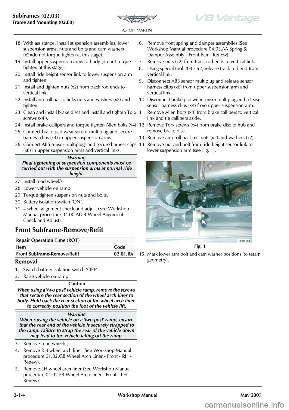
14. Remove nut and bolt from ride height sensor link to lower suspension arm (see Fig. 1).
15. Mark lower arm bolt and cam washer positions (to retain
geometry).
Warning
Final tightening of suspension components must be
carried out with the suspension arms at normal ride
height.
Repair Operation Time (ROT)
Warning
When raising the vehicle on a 'two post' ramp, ensure
that the rear end of the vehi cle is securely strapped to
the ramp. Failure to strap th e rear of the vehicle down
may lead to the vehicl e falling off the ramp.
Fig. 1