light ASTON MARTIN V8 VANTAGE 2010 Manual Online
[x] Cancel search | Manufacturer: ASTON MARTIN, Model Year: 2010, Model line: V8 VANTAGE, Model: ASTON MARTIN V8 VANTAGE 2010Pages: 947, PDF Size: 43.21 MB
Page 836 of 947
Electronics Training Programme
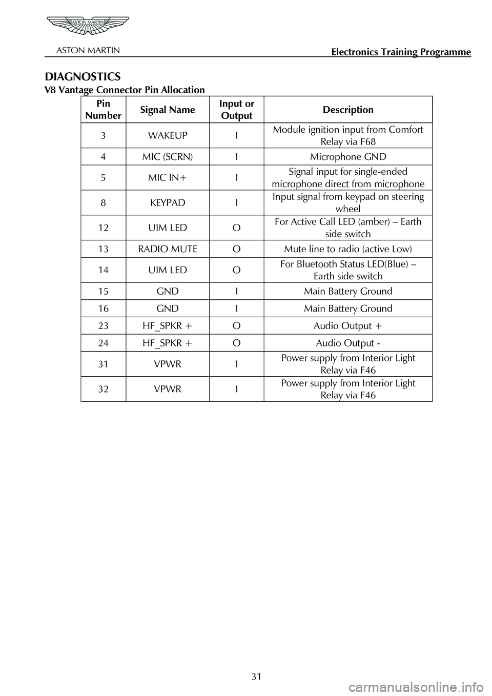
DIAGNOSTICS
V8 Vantage Connector Pin Allocation
Pin
Number Signal Name Input or
Output Description
3 WAKEUP I Module ignition input from Comfort
Relay via F68
4 MIC (SCRN) I Microphone GND
5 MIC IN+ I Signal input for single-ended
microphone direct from microphone
8 KEYPAD I Input signal from keypad on steering wheel
12 UIM LED O For Active Call LED (amber) – Earth
side switch
13 RADIO MUTE O Mute line to radio (active Low)
14 UIM LED O For Bluetooth Status LED(Blue) – Earth side switch
15 GND I Main Battery Ground
16 GND I Main Battery Ground
23 HF_SPKR + O Audio Output +
24 HF_SPKR + O Audio Output -
31 VPWR I Power supply from Interior Light Relay via F46
32 VPWR I Power supply from Interior Light Relay via F46
31
Page 837 of 947
Electronics Training Programme
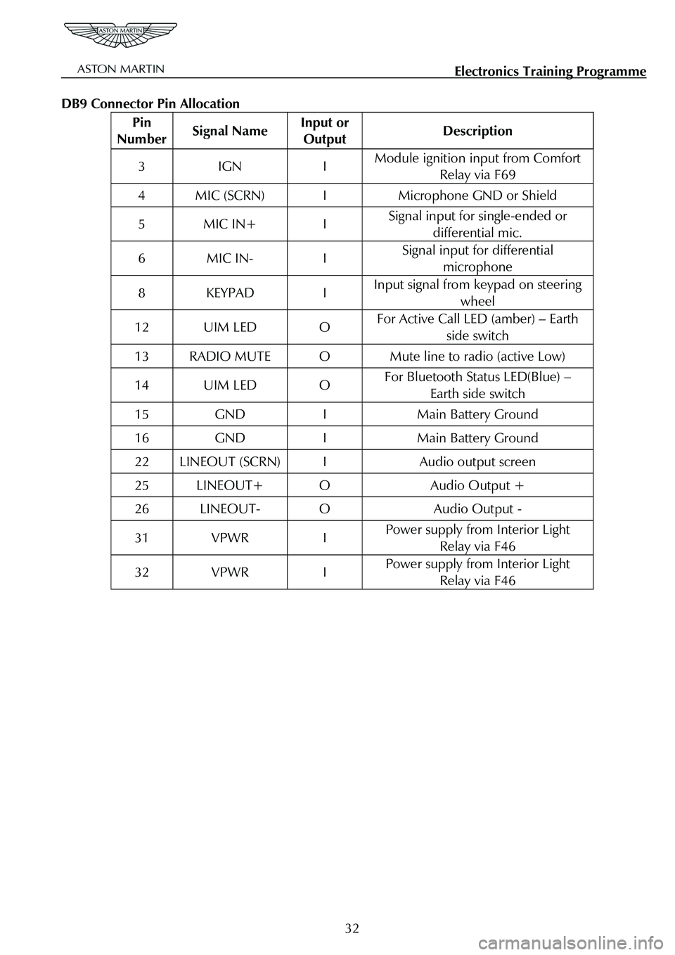
DB9 Connector Pin Allocation
Pin
Number Signal Name Input or
Output Description
3 IGN I Module ignition input from Comfort
Relay via F69
4 MIC (SCRN) I Microphone GND or Shield
5 MIC IN+ I Signal input for single-ended or
differential mic.
6 MIC IN- I Signal input for differential microphone
8 KEYPAD I Input signal from keypad on steering
wheel
12 UIM LED O For Active Call LED (amber) – Earth side switch
13 RADIO MUTE O Mute line to radio (active Low)
14 UIM LED O For Bluetooth Status LED(Blue) – Earth side switch
15 GND I Main Battery Ground
16 GND I Main Battery Ground
22 LINEOUT (SCRN) I Audio output screen
25 LINEOUT+ O Audio Output +
26 LINEOUT- O Audio Output -
31 VPWR I Power supply from Interior Light Relay via F46
32 VPWR I Power supply from Interior Light Relay via F46
32
Page 853 of 947
AML EOBD System Operation Summary
Rory O’Curry Aston Martin Lagonda CONFIDENTIAL 1 May 2009
Misfire Monitor (continued)
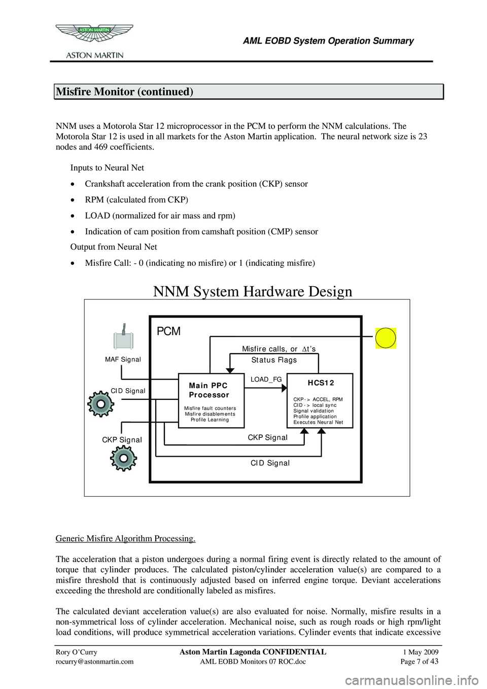
NNM uses a Motorola Star 12 microprocessor in the PCM to perform the NNM calculations. The
Motorola Star 12 is used in all markets for the Ast on Martin application. The neural network size is 23
nodes and 469 coefficients.
Inputs to Neural Net
• Crankshaft acceleration from the crank position (CKP) sensor
• RPM (calculated from CKP)
• LOAD (normalized for air mass and rpm)
• Indication of cam position from camshaft position (CMP) sensor
Output from Neural Net
• Misfire Call: - 0 (indicating no misfire) or 1 (indicating misfire)
[email protected] AML EOBD Monitors 07 ROC.doc Page 7 of 43
NNM System Hardware Design
PCM MIL
Generic Misfire Algorithm Processing.
The acceleration that a piston undergoes during a normal firing event is directly related to the amount of
torque that cylinder produces. The calculated piston/cylinder acceleration value(s) are compared to a
misfire threshold that is continuously adjusted based on inferred engine torque. Deviant accelerations
exceeding the threshold are conditionally labeled as misfires.
The calculated deviant acceleration value(s) are also evaluated for noise. Normally, misfire results in a
non-symmetrical loss of cylinder acceleration. Mechan ical noise, such as rough roads or high rpm/light
load conditions, will produce symmetrical acceleration va riations. Cylinder events that indicate excessive
MAF Signal
CKP Signal
Main PPC
Processor
HCS12HCS12LOAD_FG
CKP Signal
Misfire calls, or
Δt’s
Misfire fault counters
Status Flags
CID Signal
Misfire disablements
Profile Learning CKP
-> ACCEL, RPM
CID -> local sync
Signal validation
Profile application
Executes Neural Net
CID Signal
Page 869 of 947
AML EOBD System Operation Summary
Rory O’Curry Aston Martin Lagonda CONFIDENTIAL 1 May 2009
[email protected] AML EOBD Monitors 07 ROC.doc Page 23 of 43
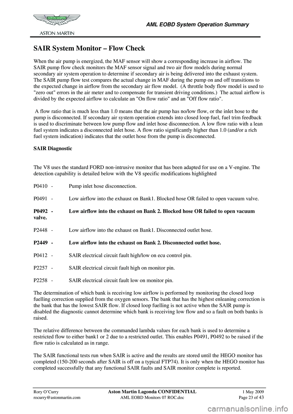
SAIR System Monitor – Flow Check
When the air pump is energized, the MAF sensor will show a corresponding increase in airflow. The
SAIR pump flow check monitors the MAF sensor signal and two air flow models during normal
secondary air system operation to determine if secondary air is being delivered into the exhaust system.
The SAIR pump flow test compares the actual change in MAF during the pump on and off transitions to
the expected change in airflow from the secondary air fl ow model. (A throttle body flow model is used to
"zero out" errors in the air meter and to compensate fo r transient driving conditions.) The actual airflow is
divided by the expected airflow to calculate an "On flow ratio" and an "Off flow ratio".
A flow ratio that is much less than 1.0 means that the air pump has no/low flow, or the inlet hose to the
pump is disconnected. If secondary air system operation ex tends into closed loop fuel, fuel trim feedback
is used to discriminate between low pump flow and in let hose disconnection. A low flow ratio with a lean
fuel system indicates a disconnected inlet hose. A flow ratio significantly higher than 1.0 (and/or a rich
fuel system indication) indicates that th e outlet hose from the pump is disconnected.
SAIR Diagnostic
The V8 uses the standard FORD non-intrusive monitor that has been adapted for use on a V-engine. The
detection capability is detailed below with the V8 specific modifications highlighted
P0410 - Pump inlet hose disconnection.
P0491 - Low airflow into the exhaust on Bank1. Blocked hose OR failed to open vacuum valve.
P0492 - Low airflow into the exhaust on Bank 2. Blocked hose OR failed to open vacuum
valve.
P2448 - Low airflow into the exhaust on Bank1. Disconnected outlet hose.
P2449 - Low airflow into the exhaust on Bank 2. Disconnected outlet hose.
P0412 - SAIR electrical circuit fault high/low on ecu control pin.
P2257 - SAIR electrical circuit fault high on monitor pin.
P2258 - SAIR electrical circuit fault low on monitor pin.
The determination of which bank is receiving low ai rflow is performed by monitoring the closed loop
fuelling correction supplied from the oxygen sensors. The bank that has the highest enleaning correction is
the bank that has the lowest SAIR flow. If closed loop fuelling is not active when the SAIR pump is
disabled the diagnostic cannot determ ine which bank is receiving low flow and so a fault on both banks is
raised.
The relative difference between the commanded lambda values for each bank is used to determine a
restricted flow to either bank1 or 2 due to a restricted outlet. This enables P0491, P0492 to be raised if the
flow ratio is calculated as in range.
The SAIR functional tests run when SAIR is active and the results are stored until the HEGO monitor has
completed (150-200 seconds after SAIR is off on a typical FTP74). It is only when the HEGO monitor has
completed successfully that any functional SAIR fa ults and SAIR monitor complete is reported.
Page 877 of 947
AML EOBD System Operation Summary
Rory O’Curry Aston Martin Lagonda CONFIDENTIAL 1 May 2009
[email protected] AML EOBD Monitors 07 ROC.doc Page 31 of 43
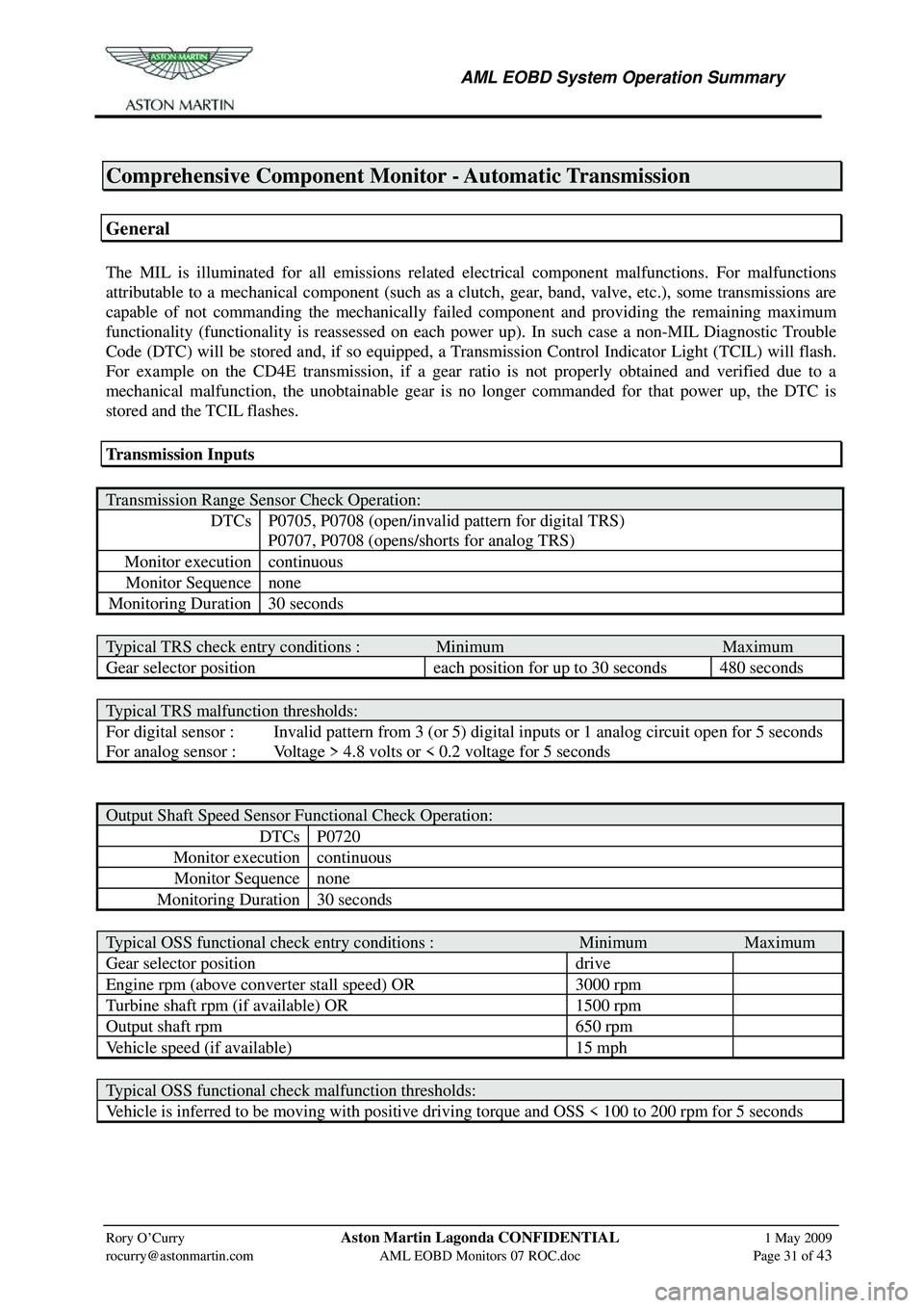
Comprehensive Component Monitor - Automatic Transmission
General
The MIL is illuminated for all emissions related electrical component malfunctions. For malfunctions
attributable to a mechanical component (such as a clutch, gear, band, valve, etc.), some transmissions are
capable of not commanding the mechanically faile d component and providing the remaining maximum
functionality (functionality is reassessed on each power up). In such case a non-MIL Diagnostic Trouble
Code (DTC) will be stored and, if so equipped, a Transmission Control Indicator Light (TCIL) will flash.
For example on the CD4E transmission, if a gear ratio is not properly obtained and verified due to a
mechanical malfunction, the unobtainable gear is no longer commanded for that power up, the DTC is
stored and the TCIL flashes.
Transmission Inputs
Transmission Range Sensor Check Operation:
DTCs P0705, P0708 (open/invalid pattern for digital TRS)
P0707, P0708 (opens/shorts for analog TRS)
Monitor execution continuous
Monitor Sequence none
Monitoring Duration 30 seconds
Typical TRS check entry conditions : Minimum Maximum
Gear selector position each position for up to 30 seconds 480 seconds
Typical TRS malfunction thresholds:
For digital sensor : Invalid pattern from 3 (or 5) digital inputs or 1 analog circuit open for 5 seconds
For analog sensor : Voltage > 4.8 volts or < 0.2 voltage for 5 seconds
Output Shaft Speed Sensor Functional Check Operation:
DTCs P0720
Monitor execution continuous
Monitor Sequence none
Monitoring Duration 30 seconds
Typical OSS functional check entry conditions : Minimum Maximum
Gear selector position drive
Engine rpm (above converter stall speed) OR 3000 rpm
Turbine shaft rpm (if available) OR 1500 rpm
Output shaft rpm 650 rpm
Vehicle speed (if available) 15 mph
Typical OSS functional check malfunction thresholds:
Vehicle is inferred to be moving with positive driving torque and OSS < 100 to 200 rpm for 5 seconds
Page 880 of 947
AML EOBD System Operation Summary
Rory O’Curry Aston Martin Lagonda CONFIDENTIAL 1 May 2009
[email protected] AML EOBD Monitors 07 ROC.doc Page 34 of 43
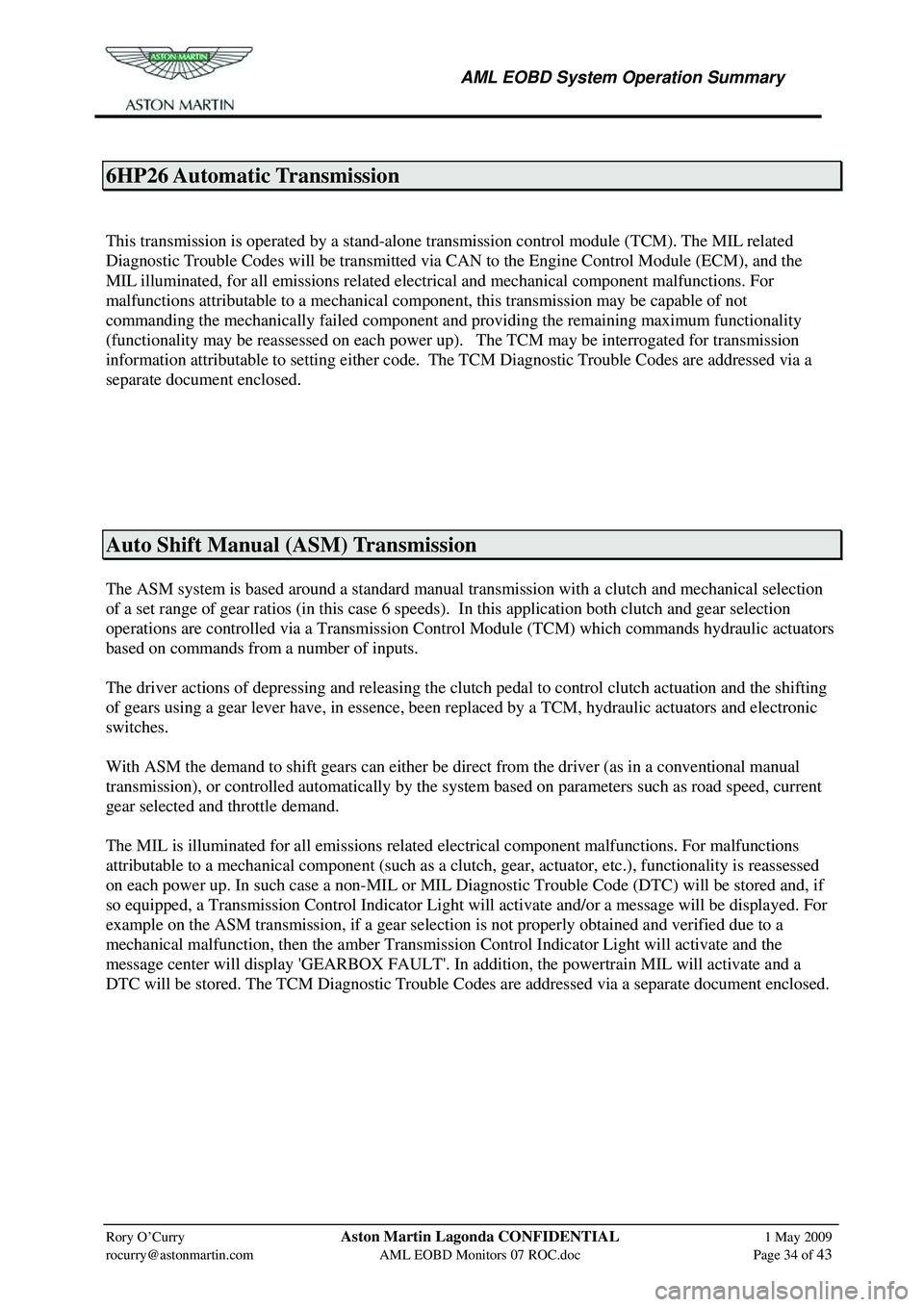
6HP26 Automatic Transmission
This transmission is operated by a stand-alone transmission control module (TCM). The MIL related
Diagnostic Trouble Codes will be transmitted via CAN to the Engine Control Module (ECM), and the
MIL illuminated, for all emissions related electrical and mechanical component malfunctions. For
malfunctions attributable to a mechanical component, this transmission may be capable of not
commanding the mechanically failed component a nd providing the remaining maximum functionality
(functionality may be reassessed on each power up). The TCM may be interrogated for transmission
information attributable to setting either code. The TCM Diagnostic Trouble Codes are addressed via a
separate document enclosed.
Auto Shift Manual (ASM) Transmission
The ASM system is based around a standard manual transmission with a clutch and mechanical selection
of a set range of gear ratios (in this case 6 speeds). In this application both clutch and gear selection
operations are controlled via a Transmission Contro l Module (TCM) which commands hydraulic actuators
based on commands from a number of inputs.
The driver actions of depressing and releasing the clutch pedal to control clutch actuation and the shifting
of gears using a gear lever have, in essence, been re placed by a TCM, hydraulic actuators and electronic
switches.
With ASM the demand to shift gears can either be direct from the driver (as in a conventional manual
transmission), or controlled automatically by the system based on parameters such as road speed, current
gear selected and throttle demand.
The MIL is illuminated for all emissions related electrical component malfunctions. For malfunctions
attributable to a mechanical component (such as a cl utch, gear, actuator, etc.), functionality is reassessed
on each power up. In such case a non-MIL or MIL Diagnos tic Trouble Code (DTC) will be stored and, if
so equipped, a Transmission Control Indicator Light will activate and/or a message will be displayed. For
example on the ASM transmission, if a gear selection is not properly obtained and verified due to a
mechanical malfunction, then the amber Transmission Control Indicator Light will activate and the
message center will display 'GEARBOX FAULT'. In addition, the powertrain MIL will activate and a
DTC will be stored. The TCM Diagnostic Trouble Cod es are addressed via a separate document enclosed.
Page 903 of 947
2009 MY OBD-II Documentation4.7L, Aston Martin V8 VantageAston Martin / Ford Confidential
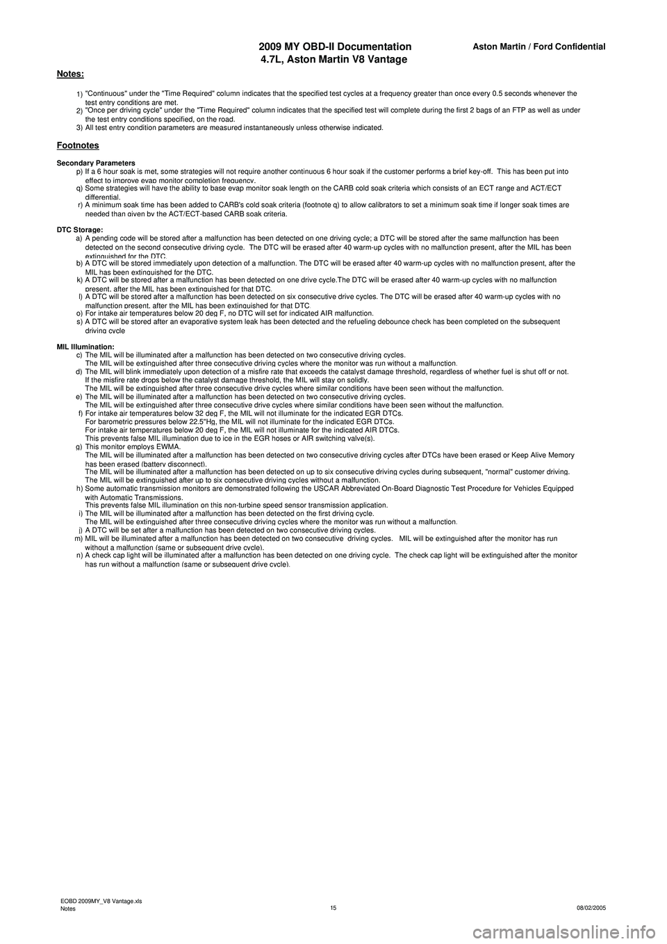
1) "Continuous" under the "Time Required" column indicates that the specified test cycles at a frequency greater than once every 0.5 seconds whenever the
test entry conditions are met.
2) "Once per driving cycle" under the "Time Required" column indicates that the specified test will complete during the first 2 bags of an FTP as well as under
the test entr
y conditions specified, on the road.
3)All test entry condition parameters are measured instantaneously unless otherwise indicated.
p) If a 6 hour soak is met, some strategies will not require another continuous 6 hour soak if the customer performs a brief key-off. This has been put into
effect to improve evap monitor completion frequency.
q) Some strategies will have the ability to base evap monitor soak length on the CARB cold soak criteria which consists of an ECT range and ACT/ECT
differential.
r) A minimum soak time has been added to CARB's cold soak criteria (footnote q) to allow calibrators to set a minimum soak time if longer soak times are
n
eeded than given by the ACT/ECT-based CARB soak criteria.
a) A pending code will be stored after a malfunction has been detected on one driving cycle; a DTC will be stored after the same malfunction has been detected on the second consecutive driving cycle. The DTC will be erased after 40 warm-up cycles with no malfunction present, after the MIL has been
extinguished for the DTC.b) A DTC will be stored immediately upon detection of a malfunction. The DTC will be erased after 40 warm-up cycles with no malfunction present, after the MIL has been extinguished for the DTC.k) A DTC will be stored after a malfunction has been detected on one drive cycle.The DTC will be erased after 40 warm-up cycles with no malfunction present, after the MIL has been extinguished for that DTC.l) A DTC will be stored after a malfunction has been detected on six consecutive drive cycles. The DTC will be erased after 40 warm-up cycles with no malfunction present, after the MIL has been extinguished for that DTC.o)For intake air temperatures below 20 deg F, no DTC will set for indicated AIR malfunction.
s) A DTC will be stored after an evaporative system leak has been detected and the refueling debounce check has been completed on the subsequent
driving cycle
c)The MIL will be illuminated after a malfunction has been detected on two consecutive driving cycles.
The MIL will be extinguished after three consecutive driving cycles where the monitor was run without a malfunction.d)The MIL will blink immediately upon detection of a misfire rate that exceeds the catalyst damage threshold, regardless of whether fuel is shut off or not.
If the misfire rate drops below the catalyst damage threshold, the MIL will stay on solidly.
The MIL will be extinguished after three consecutive drive cycles where similar conditions have been seen without the malfunction.e)The MIL will be illuminated after a malfunction has been detected on two consecutive driving cycles.
The MIL will be extinguished after three consecutive drive cycles where similar conditions have been seen without the malfunction.f)For intake air temperatures below 32 deg F, the MIL will not illuminate for the indicated EGR DTCs.
For barometric pressures below 22.5"Hg, the MIL will not illuminate for the indicated EGR DTCs.
For intake air temperatures below 20 deg F, the MIL will not illuminate for the indicated AIR DTCs.
This prevents false MIL illumination due to ice in the EGR hoses or AIR switching valve(s).g)This monitor employs EWMA.
The MIL will be illuminated after a malfunction has been detected on two consecutive driving cycles after DTCs have been erased or Keep Alive Memory
h
as been erased (battery disconnect).
The MIL will be illuminated after a malfunction has been detected on up to six consecutive driving cycles during subsequent, "normal" customer driving.
The MIL will be extinguished after up to six consecutive driving cycles without a malfunction.
h) Some automatic transmission monitors are demonstrated following the USCAR Abbreviated On-Board Diagnostic Test Procedure for Vehicles Equipped
wi
th Automatic Transmissions.
This prevents false MIL illumination on this non-turbine speed sensor transmission application.
i)The MIL will be illuminated after a malfunction has been detected on the first driving cycle.
The MIL will be extinguished after three consecutive driving cycles where the monitor was run without a malfunction.j)A DTC will be set after a malfunction has been detected on two consecutive driving cycles.
m) MIL will be illuminated after a malfunction has been detected on two consecutive driving cycles. MIL will be extinguished after the monitor has run
wi
thout a malfunction (same or subsequent drive cycle).
n) A check cap light will be illuminated after a malfunction has been detected on one driving cycle. The check cap light will be extinguished after the monitor
h
as run without a malfunction (same or subsequent drive cycle).
MIL Illumination:
Notes:
Footnotes
Secondary Parameters
DTC Stora
ge:
EOBD 2009MY_V8 Vantage.xls
Notes 08/02/2005
15
Page 931 of 947
Aston Martin V12 Family
2009 MY V12 Family EOBDincl. V12 Vantage
Aston Martin/Ford Confidential
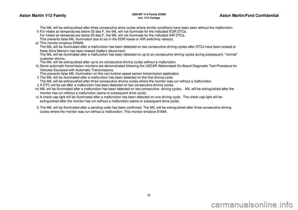
The MIL will be extin
guished after three consecutive drive c
ycles where similar conditions have been seen without the malfunction.
f
)For intake air tem
peratures below 32 de
g F, the MIL will not illuminate for the indicated EGR DTCs.
For intake air tem
peratures below 20 de
g F, the MIL will not illuminate for the indicated AIR DTCs.
This
prevents false MIL illumination due to ice in the EGR hoses or AIR switchin
g valve
(s).
g)
This monitor em
ploys EWMA.
The MIL will be illuminated after a malfunction has been detected on two consecutive driving cycles after DTCs have been erased or
Kee
p Alive Memor
y has been erased
(batter
y disconnect
).
The MIL will be illuminated after a malfunction has been detected on up to six consecutive driving cycles during subsequent, "normal"
customer drivin
g.
The MIL will be extin
guished after u
p to six consecutive drivin
g cycles without a malfunction.
h) Some automatic transmission monitors are demonstrated following the USCAR Abbreviated On-Board Diagnostic Test Procedure for
Vehicles E
quipp
ed with Automatic Transmissions.
This
prevents false MIL illumination on this non-turbine s
peed sensor transmission a
pp
lication.
i
)The MIL will be illuminated after a malfunction has been detected on the first drivin
g cycle.
The MIL will be extin
guished after three consecutive drivin
g cycles where the monitor was run without a malfunction.
j)A DTC will be set after a malfunction has been detected on two consecutive drivin
g cycles.
m) MIL will be illuminated after a malfunction has been detected on two consecutive driving cycles. MIL will be extinguished after the
monitor has run without a malfunction
(same or subse
quent drive c
ycle
).
n) A check cap light will be illuminated after a malfunction has been detected on one driving cycle. The check cap light will be
extinguished after the monitor has run without a malfunction (same or subsequent drive cycle).
t) The MIL will be illuminated after a pending code has been confirmed. The MIL will be extinguished after three consecutive driving c
ycles where the monitor was run without a malfunction. This monitor em
ploye EVMA.
20