3-2-1 ASTON MARTIN V8 VANTAGE 2010 Workshop Manual
[x] Cancel search | Manufacturer: ASTON MARTIN, Model Year: 2010, Model line: V8 VANTAGE, Model: ASTON MARTIN V8 VANTAGE 2010Pages: 947, PDF Size: 43.21 MB
Page 3 of 947
Contents
Issue 5, January 2010 Workshop Manual 0-0-3
V8 Vantage Workshop Manual
Contents
IntroductionWelcome .............................................................. 0-0-6
Safety Precautions ................................................. 0-0-7
Lifting and Jacking ................................................. 0-0-9
Vehicle Recovery ................................................ 0-0-10
Vehicle Identification Number ............................ 0-0-11
Body System (01.00) Body Structure (01.01) .......................................... 1-1-4
Front End System (01.02) ...................................... 1-2-1
Body Closures (01.03) ........................................... 1-3-1
Interior Trim (01.05) ............................................. 1-4-1
Exterior Trim (01.08) ............................................. 1-8-1
Mirrors (01.09) ...................................................... 1-9-1
Seating (01.10).................................................... 1-10-1
Glass, Frame and Mechanism (01.11) .................. 1-11-1
Instrument Panel (IP) (01.12) . .............................. 1-12-1
Handles and Lock Mechanisms (01.14) ............... 1-14-1
Wipers and Washer System (01.16)..................... 1-16-1
Convertible Roof and Roof Opening
Subsystem (01.17)................ ...............................1-17-1
Bumpers (01.19) ................................................. 1-19-1
Restraining Devices (01.20) .... ............................. 1-20-1
Frame and Mounting (02.00) Subframes (02.03) ................................................. 2-1-2
Engine System (03.00) Engine Assembly....................................................3-0-3
Engine Structure (03.01)........................................ 3-1-1
Lubrication System (03.02).................................... 3-2-1
Cooling System (03.03) ......................................... 3-3-1
Fuel Charging System (03.04) ................................ 3-4-1
Accessory Drive System (03.05)............................. 3-5-1
Engine Cranking System (03. 06) ............................ 3-6-1
Valve Train (03.09) ............................................... 3-9-1
Engine Sealing (03.10)......................................... 3-10-1
Power Conversion (03.11)................................... 3-11-1
Evaporative Emissions (03.13) ............................. 3-11-1
Engine Management System (0 3.14).................... 3-14-1
Throttle Control (03.16) ...... ................................ 3-16-1
Foot Operated Control (03.18)............................ 3-18-1
Suspension (04.00) Road Wheel Alignment (04.00) ............................. 4-0-2
Front Suspension (04.01)....................................... 4-1-1
Rear Suspension (04.02)........................................ 4-2-1
Shock Absorber System (04.03) ............................. 4-3-1
Road Wheels and Tyres (04.04) ............................ 4-4-1
Driveline (05.00) Driveshaft (05.01) ................................................. 5-1-2
Halfshafts (05.05) .................................................. 5-2-1 Brake System (06.00)
Front Disc Brake (06.03) ....................................... 6-3-2
Rear Disc Brakes (06.04) ....................................... 6-4-1
Hand Brake (06.05) .............................................. 6-5-1
Brake Actuation System (06.06 ) ............................ 6-6-1
Power Brake System (06.07) ................................. 6-7-1
Anti-lock Braking System (06.09)........................... 6-9-1
Transmission (07.00) Transmission Cooling (07.02) ................................ 7-0-2
Manual Transmission (07.03) ................................ 7-3-1
Automatic Control System (07.05)......................... 7-5-1
Manual Control System (07.06) ............................. 7-6-1
Automatic Shifting Subsytem (07.11) .................. 7-11-1
Clutch (08.00) Clutch Controls (08.02) ......................................... 8-1-2
Exhaust (09.00) Exhaust Overview ................................................. 9-1-2
Silencer Assembly (09.01) ..................................... 9-1-3
Pipes and Supports (09.03) ................................... 9-2-1
Exhaust Protection (09.04) .................................... 9-3-1
Fuel (10.00) Fuel Tank and Lines (10.01) ................................ 10-1-2
Steering (11.00) Steering Gear (11.01) .......................................... 11-1-2
Power Steering (11.02)........................................ 11-2-1
Steering Column (11.04) ..................................... 11-4-1
Steering Column Switches (1 1.05) ....................... 11-5-1
Steering Wheel (11.06) ....................................... 11-6-1
Climate Control (12.00) Body Ventilation system (12.01) .......................... 12-1-2
Heater System (12.02) ........................................ 12-2-1
Air Conditioning (A/C) System (12.03) ................. 12-3-1
Information, Gauge and Warning (13.00) Instrument Cluster (13.01) .................................. 13-1-2
Power Supply (14.00) Battery System (14.01) ........................................ 14-1-2
Alternator and Regulator System (14.02) ............. 14-2-1
Vehicle Entertainment (15.00) Audio System (15.01)................................ ..........15-1-2
Antenna (15.02).................................................. 15-2-1
Vacuum Distribution (16.00) Body Vacuum System (16.01) ............................. 16-1-2
Lighting (17.00) Front Lights (17.01) ............................................. 17-1-2
Interior Lighting (17.02) ...................................... 17-2-1
Rear Lights (17.03) .............................................. 17-3-1
Lighting Mechanisms (17.04). .............................. 17-4-1
Page 233 of 947
Issue 5, January 2010 Workshop Manual 3-0-1
Engine System (03.00)
Contents
Engine Assembly (03.00) ....................................... 3-0-3Description ............................................................. 0-3
Maintenance ........................................................... 0-4Engine Assembly-Renew ........................................ 0-4
Engine Assembly-Remove for Access and Refit ....... 0-4
Engine Structure (03.01) ........................................ 3-1-1 Description ............................................................. 1-1Engine Block .......................................................... 1-1
Cylinder Block Drain Plug ...................................... 1-2
Knock Sensors........................................................ 1-3
Bedplate ................................................................ 1-3
Engine Mountings .................................................. 1-3
Cylinder Heads ...................................................... 1-4
Inlet/Exhaust Manifolds .......................................... 1-4
Specifications.......................................................... 1-4
Maintenance ........................................................... 1-5 Upper Intake Manifold Assembly (LHD) - Renew ... 1-5
Upper Intake Manifold Asse mbly (RHD) - Renew ... 1-6
Upper Intake Manifold Assembly Gasket (LHD)
- Renew ................................................................. 1-8
Upper Intake Manifold Assembly Gasket (RHD)
- Renew ................................................................. 1-9
Intake Manifold Assembly - Remove for Access
and Refit (With Engine Removed)......................... 1-11
RH/LH Cylinder Head Gasket - Renew................. 1-12
RH/LH Cylinder Head - Overhaul ........................ 1-13
Cylinder Head (Engine Set) - Overhaul ................. 1-14
Valve Set (Engine Set) - Renew
(including de-coke) .............................................. 1-15
Inlet Valve (Set) - Renew ...................................... 1-16
Exhaust Valve (Set) - Renew ................................. 1-16
Spring (Valve Set) - Renew ................................... 1-17
Spring (Inlet Valve Set) - Renew ........................... 1-18
Inlet and Exhaust Valve Seal (Engine Set) - Renew 1-19
Spring (Valve Exhaust Set) - Renew....................... 1-19
RH/LH Cylinder Head Gasket - Renew (with
Engine Removed) ................................................. 1-20
Cylinder Head Gasket (E ngine Set) - Renew (with
Engine Removed) ................................................. 1-21
Lubrication System (03.02) .. .................................. 3-2-1
Dry Sump System .................................................. 2-1
Specifications.......................................................... 2-2 Engine Oil Specification ......................................... 2-2
Maintenance ........................................................... 2-2 Oil Pressure Pump to Sump Gasket - Renew .......... 2-2
Oil Pump Chain - Renew ....................................... 2-2
Oil Sump Pan - Renew........................................... 2-3
Oil Sump Pan - Remove and Reseal ....................... 2-5
Oil Cooler - Renew ................................................ 2-8
Oil Cooler Tank Assembly - Renew ........................ 2-9
Thermostat - Renew ............................................... 2-9
Oil Cooler Tank Pipe Assembly - Renew .............. 2-10
Oil Thermostat to Tank Tube Assembly - Renew .. 2-10
Oil Pump Inlet Tube Assemb ly - Renew ............... 2-11 Oil Pump Inlet Tube Assembly - Renew ............... 2-12
Oil Pump Outlet Tube Asse
mbly - Renew ............ 2-12
Oil Thermostat Cooler Pipe Assembly - Renew .... 2-13
Oil Temperature Controller - Renew .................... 2-14
Oil Sump Pan - Renew (with Engine Removed) .... 2-14
Oil Sump Pan - Remove and Reseal
(with Engine Removed) ........................................ 2-17
Cooling System (03.03) ......................................... 3-3-1 Description ............................................................. 3-1Water Pump .......................................................... 3-1
Thermostat ............................................................ 3-1
Radiator................................................................. 3-1
Cooling Fans .......................................................... 3-1
Coolant Reservoir .................................................. 3-1
Engine Oil Cooler .................................................. 3-2
Specifications......................................................... 3-2
Torque Figures ....................................................... 3-2
Maintenance ........................................................... 3-2 Coolant-Drain/Fill .................................................. 3-2
Thermostat - Renew............................................... 3-3
Water Pump - Renew ............................................ 3-3
Water Pump Pulley - Renew .................................. 3-3
Oil Temperature Controller - Renew ...................... 3-4
Radiator Fan and Motor Assembly - Remove and
Install ..................................................................... 3-4
Radiator and Condenser Assembly - Renew ........... 3-5
Radiator Assembly - Renew.................................... 3-5
Air Conditioning Condenser - Renew ..................... 3-6
Radiator Fan Modulator - Remove and Install......... 3-6
Expansion Tank Assembly - Renew ........................ 3-6
Coolant Recovery Tank Assembly - Remove and
Install ..................................................................... 3-7
Engine Coolant Reservoir Hose - Renew ................ 3-8
Water Inlet/Outlet Manifold - Renew ..................... 3-8
Engine Electric Coolant Temperature Sensor
- Renew ............................................................... 3-10
Thermostat Cover - Renew .................................. 3-11
Fuel Charging System (03.04)................................ 3-4-1 Safety Precautions .................................................. 4-1
Maintenance ........................................................... 4-2Fuel Rails - Renew ................................................. 4-2
Fuel Injection Pressure Sensor - Renew .................. 4-3
Fuel Temperature Sensor - Renew ......................... 4-3
Fuel Injector Engine Set - Renew............................ 4-4
Fuel Injector - Each - LH Bank - Renew.................. 4-5
Fuel Injector - Each - RH Bank - Renew ................. 4-5
Engine Set - Fuel Injector - LH Bank - Renew ......... 4-6
Engine Set - Fuel Injector - RH Bank - Renew......... 4-6
Accessory Drive System (03.05) ............................ 3-5-1 Description ............................................................. 5-1Auxiliary Drives...................................................... 5-1
Automatic Belt Tensioner ....................................... 5-1
Specifications ......................................................... 5-1
Maintenance ........................................................... 5-1
Page 275 of 947
Lubrication System (03.02)
Engine (03.00)
Issue 5, Janauary 2010 Workshop Manual 3-2-1
Engine (03.00)
Lubrication System (03.02)
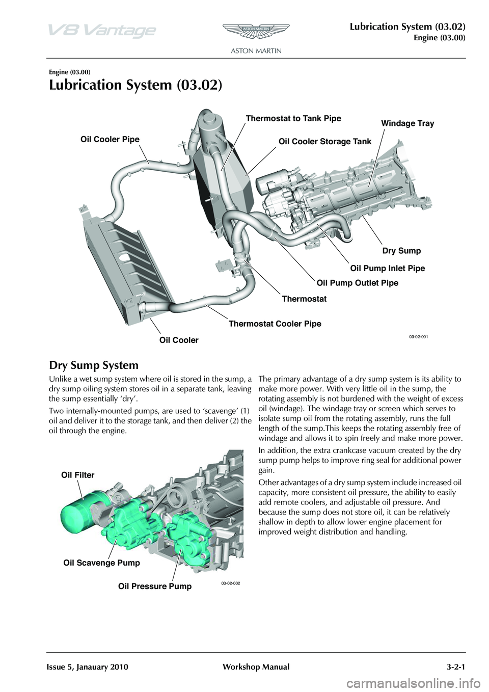
Dry Sump System
Unlike a wet sump system where oil is stored in the sump, a
dry sump oiling system stores oil in a separate tank, leaving
the sump essentially ‘dry’.
Two internally-mounted pumps, are used to ‘scavenge’ (1)
oil and deliver it to the storage tank, and then deliver (2) the
oil through the engine. The primary advantage of a dry sump system is its ability to
make more power. With very little oil in the sump, the
rotating assembly is not burdened with the weight of excess
oil (windage). The windage tray or screen which serves to
isolate sump oil from the rota
ting assembly, runs the full
length of the sump.This keeps the rotating assembly free of
windage and allows it to spin freely and make more power.
In addition, the extra crankcase vacuum created by the dry
sump pump helps to improve ring seal for additional power
gain.
Other advantages of a dry sump system include increased oil
capacity, more consistent oil pr essure, the ability to easily
add remote coolers, and adjustable oil pressure. And
because the sump does not stor e oil, it can be relatively
shallow in depth to allow lower engine placement for
improved weight distribution and handling.
Oil Cooler Oil Cooler Storage Tank
Oil Cooler Pipe
Thermostat
Thermostat to Tank Pipe
Thermostat Cooler Pipe Dry Sump
Oil Pump Outlet Pipe Oil Pump Inlet PipeWindage Tray03-02-001
Oil Filter
Oil Scavenge Pump Oil Pressure Pump
03-02-002
Page 284 of 947
Lubrication System (03.02)
Engine (03.00)3-2-10 Workshop Manual Issue 5, Janauary 2010
5. Remove breather valve bracket for access (nuts x2 bolt x1).
6. Remove thermostat housing from manifold (bolt x3).
7. Remove thermostat and sealing ring.
Installation
1. Install new thermostat and sealing ring .
2. Install thermostat housing (torque).
3. Install breather valve bracket.
4. Install breather hoses (x3) and clip.
5. Clip engine harness.
6. Install breather valve.
7. Refill coolant (refer to Workshop Manual procedure 03.03.AD Coolant - Drain and Refill).
Oil Cooler Tank Pipe Assembly - Renew
Removal
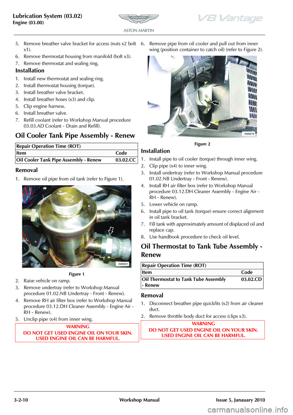
1. Remove oil pipe from oil tank (refer to Figure 1).
Figure 1
2. Raise vehicle on ramp.
3. Remove undertray (refer to Workshop Manual
procedure 01.02.NB Undertray - Front - Renew).
4. Remove RH air filter box (refer to Workshop Manual
procedure 03.12.DH Cleaner Assembly - Engine Air -
RH - Renew).
5. Unclip pipe (x4) from inner wing. 6. Remove pipe from oil cool
er and pull out from inner
wing (position container to catch oil) (refer to Figure 2).
Figure 2
Installation
1. Install pipe to oil cooler (torque) through inner wing .
2. Clip pipe (x4) to inner wing.
3. Install undertray (refer to Workshop Manual procedure 01.02.NB Undertray - Front - Renew).
4. Install RH air filter box (refer to Workshop Manual
procedure 03.12.DH Cleaner Assembly - Engine Air -
RH - Renew).
5. Lower vehicle on ramp.
6. Install pipe to oil tank (torque) ensure correct alignment in oil tank bracket.
7. Fill tank with approximatel y amount of displaced oil and
replace cap.
8. Use handbook procedure to check oil level.
Oil Thermostat to Tank Tube Assembly -
Renew
Removal
1. Disconnect breather pipe qu ickfits (x2) from air cleaner
duct.
2. Remove throttle body duct for access (clips x3).
Repair Operation Time (ROT)
A030241Repair Operation Time (ROT)
ItemCode
Oil Thermostat to Tank Tube Assembly
- Renew 03.02.CD
WAR NI NG
DO NOT GET USED ENGINE OIL ON YOUR SKIN. USED ENGINE OIL CAN BE HARMFUL.
A030219
Page 285 of 947

Lubrication System (03.02)
Engine (03.00)
Issue 5, Janauary 2010 Workshop Manual 3-2-11
3. Remove pipes from oil tank (refer to Figure 1).
Figure 1
4. Raise vehicle on ramp.
5. Remove undertray (refer to Workshop Manual procedure. 01.02.NB Undertray - Front - Renew).
6. Remove pipe from oil thermostat (position container to catch oil) (refer to Figure 2).
Figure 2
Installation
1. Install pipe to oil thermostat (torque) ensure correct alignment in oil tank bracket.
2. Install undertray (refer to Workshop Manual procedure 01.02.NB Undertray - Front - Renew).
3. Lower vehicle on ramp.
4. Install oil pipe to tank.
5. Install throttle body duct.
6. Connect breather pipe quickf its (x2) to air cleaner duct.
7. Fill tank with approximately amount of displaced oil and replace cap.
8. Use handbook procedure to check oil level.
Oil Pump Inlet Tube Assembly - Renew
Removal
1. Remove the PAS pump (refer to Workshop Manual procedure 03.05.AA Pump - Power Steering - Renew).
2. Remove pipe from oil contro ller (position container to
catch oil).
3. Remove bolt, pipes to bracket (refer to Figure 1).
Figure 1
4. Remove LH exhaust manifo ld (refer to Workshop
Manual procedure 09.00.CD Gasket - Exhaust Manifold
- LH - Renew).
5 . R e m o v e h a r n e s s t o p i p e c l i p ( r e f e r t o F i g u r e 2 ) .
Figure 2
6. Remove bolts that attach the oil pipes to block.
7. Release both pipes from bl ock and remove inlet pipe.
Installation
1. Renew O-ring on remaining oil pipe.
2. Install inlet pipe and position both pipes into block.
A030244
A030246
Repair Operation Time (ROT)
A030248
A030247
Page 286 of 947

Lubrication System (03.02)
Engine (03.00)3-2-12 Workshop Manual Issue 5, Janauary 2010
3. Install bolts that attach th e oil pipes to block (torque).
4. Install LH exhaust manifold (refer to Workshop Manual
procedure 09.00.CD Gasket - Exhaust Manifold - LH -
Renew).
5. Install bolt, pipes to bracket.
6. Install harness clip to pipe.
7. Install pipe to oil controller (torque).
8. Install P.A.S pump (refer to Workshop Manual procedure 03.05.AA Pump - Power Steering - Renew).
9. Fill tank with approximately amount of displaced oil and replace cap.
10. Use handbook procedure to check oil level.
Oil Pump Inlet Tube Assembly - Renew
Removal
1. Remove the PAS pump (refer to Workshop Manual procedure 03.05.AA Pump - Power Steering - Renew).
2. Remove pipe from oil controller (position container to catch oil).
3. Remove bolt, pipes to bracket (refer to Figure 1).
Figure 1
4. Remove LH exhaust manifold (refer to Workshop Manual procedure 09.00.CD Gasket - Exhaust Manifold
- LH - Renew). 5 . R e m o v e h a r n e s s t o p i p e c l i p ( r e f e r t o F i g u r e 2 ) .
Figure 2
6. Remove bolts that attach the oil pipes to block.
7. Release both pipes from bl
ock and remove inlet pipe.
Installation
1. Renew O-ring on remaining oil pipe.
2. Install inlet pipe and position both pipes into block.
3. Install bolts that attach the oil pipes to block (torque).
4. Install LH exhaust manifold (refer to Workshop Manual
procedure 09.00.CD Gasket - Exhaust Manifold - LH -
Renew).
5. Install bolt, pipes to bracket.
6. Install harness clip to pipe.
7. Install pipe to oil controller (torque).
8. Install P.A.S pump (refer to Workshop Manual procedure 03.05.AA Pump - Power Steering - Renew).
9. Fill tank with approximatel y amount of displaced oil and
replace cap.
10. Use handbook procedure to check oil level.
Oil Pump Outlet Tube Assembly - Renew
Removal
1. Remove PAS pump (refer to Workshop Manual procedure 03.05.AA Pump - Power Steering - Renew).
Repair Operation Time (ROT)
A030248
Repair Operation Time (ROT)
ItemCode
Oil Pump Outlet Tube Assembly -
Renew 03.02.CF
WAR NI NG
DO NOT GET USED ENGINE OIL ON YOUR SKIN. USED ENGINE OIL CAN BE HARMFUL.
A030247
Page 287 of 947

Lubrication System (03.02)
Engine (03.00)
Issue 5, Janauary 2010 Workshop Manual 3-2-13
2. Remove pipe from oil tank (position container to catch oil) (refer to Figure 1).
Figure 1
3. Remove bolt, pipes to bracket (refer to Figure 2).
Figure 2
4. Remove LH exhaust manifold (refer to Workshop Manual procedure 09.00.CD Gasket - Exhaust Manifold
- LH - Renew).
5. Remove harness to pipe clip (refer to Figure 3).
Figure 3
6. Remove bolts that attach the oil pipes to block.
7. Release both pipes from block and remove outlet pipe.
Installation
1. Renew O-ring on remaining oil pipe.
2. Install outlet pipe and position both pipes into block.
3. Install bolts that attach the oil pipes to block (torque).
4. Install bolt, pipes to bracket.
5. Install harness clip to pipe.
6. Install pipe to oil tank (torque).
7. Install LH exhaust manifold (refer to Workshop Manual
procedure 09.00.CD Gasket - Exhaust Manifold - LH -
Renew).
8. Install P.A.S pump (refer to Workshop Manual procedure 03.05.AA Pump - Power Steering - Renew).
9. Fill tank with approximately amount of displaced oil and replace cap.
10. Use handbook procedure to check oil level.
Oil Thermostat Cooler Pipe Assembly -
Renew
Removal
1. Raise vehicle on ramp.
2. Remove undertray (refer to Workshop Manual procedure 01.02.NB Undertray - Front - Renew).
3. Remove LH air filter box (refer to Workshop Manual
procedure 03.12.AB Air Filter Box LH Renew).
4. Remove pipe from oil thermo stat (position container to
catch oil) (refer to Figure 1).
Figure 1
5. Unclip pipe (x4) from inner wing.
A030244
A030248
A030247
Repair Operation Time (ROT)
A030240
Page 288 of 947

Lubrication System (03.02)
Engine (03.00)3-2-14 Workshop Manual Issue 5, Janauary 2010
6. Remove pipe from oil cooler and pull out from inner wing (position container to catch oil) (refer to Figure 2).
Figure 2
Installation
1. Install pipe to oil cooler (torque) through inner wing .
2. Clip pipe (x4) to inner wing.
3. Install pipe to oil thermostat and ensure correct alignment in oil tank bracket.
4. Install undertray (refer to Workshop Manual procedure 01.02.NB Undertray - Front - Renew).
5. Lower vehicle on ramp.
6. Install LH air filter box (refer to Workshop Manual procedure 03.12.AB Air Filter Box LH Renew).
7. Fill tank with approximately amount of displaced oil and replace cap.
8. Use handbook procedure to check oil level.
Oil Temperature Controller - Renew
Remove
1. Raise vehicle on ramp.
2. Remove undertray (refer to Workshop Manual procedure 01.02.NB Undertray - Front - Renew). 3. Remove pipes from oil thermostat (position container to
catch oil) (refer to Figure 1).
Figure 1
4. Remove controller fr om body (bolts x2).
Install
1. Install controller to body (bolts x2) (torque).
2. Install pipes to oil thermost at (torque) ensure correct
alignment in oil tank bracket.
3. Install undertray (refer to Workshop Manual procedure 01.02.NB Undertray - Front - Renew).
4. Fill tank with approximatel y amount of displaced oil and
replace cap.
5. Use handbook procedure to check oil level.
6. Lower vehicle on ramp.
Oil Sump Pan - Renew (with Engine
Removed
)
Removal
1. Remove oil sump (refer to Workshop Manual procedure 03.02.CN Pan - Oil Sump - Remove and Reseal With
Engine Removed).
Repair Operation Time (ROT)
A030220
Repair Operation Time (ROT)
ItemCode
Oil Sump Pan-Renew (with Engine
Removed) 03.02.CM
WAR NI NG
DO NOT GET USED ENGINE OIL ON YOUR SKIN. USED ENGINE OIL CAN BE HARMFUL.
A030242
Page 289 of 947
Lubrication System (03.02)
Engine (03.00)
Issue 5, Janauary 2010 Workshop Manual 3-2-15
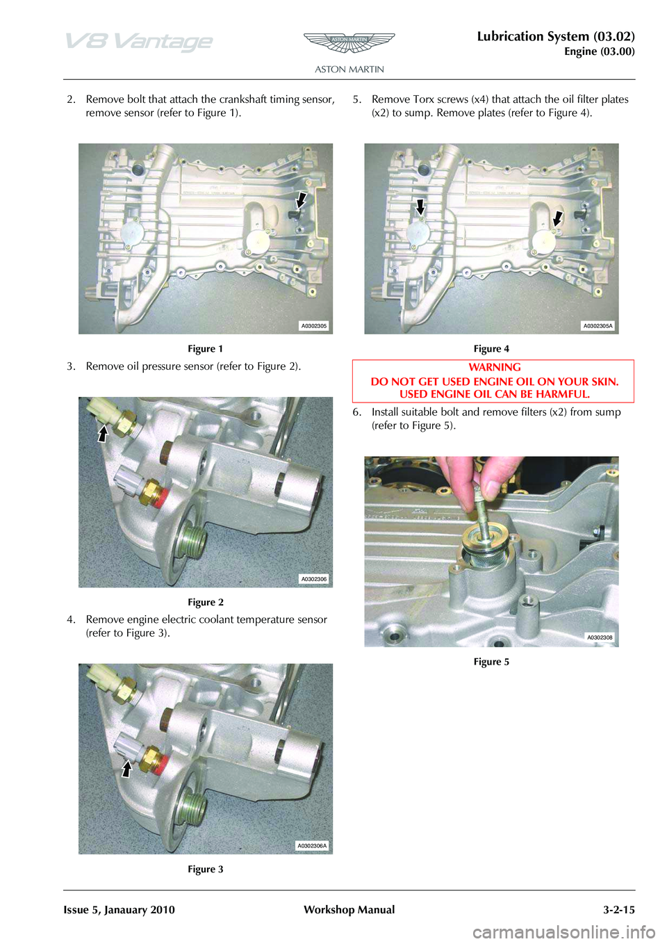
2. Remove bolt that attach the crankshaft timing sensor, remove sensor (refer to Figure 1).
3. Remove oil pressure sens or (refer to Figure 2).
4. Remove engine electric coolant temperature sensor (refer to Figure 3). 5. Remove Torx screws (x4) that
attach the oil filter plates
(x2) to sump. Remove plates (refer to Figure 4).
6. Install suitable bolt and re move filters (x2) from sump
(refer to Figure 5).
Figure 1
Figure 2
Figure 3
A0302305
A0302306
A0302306A
Figure 4
WA R N I N G
DO NOT GET USED ENGINE OIL ON YOUR SKIN. USED ENGINE OIL CAN BE HARMFUL.
Figure 5
A0302305A
A0302308
Page 290 of 947
Lubrication System (03.02)
Engine (03.00)3-2-16 Workshop Manual Issue 5, Janauary 2010
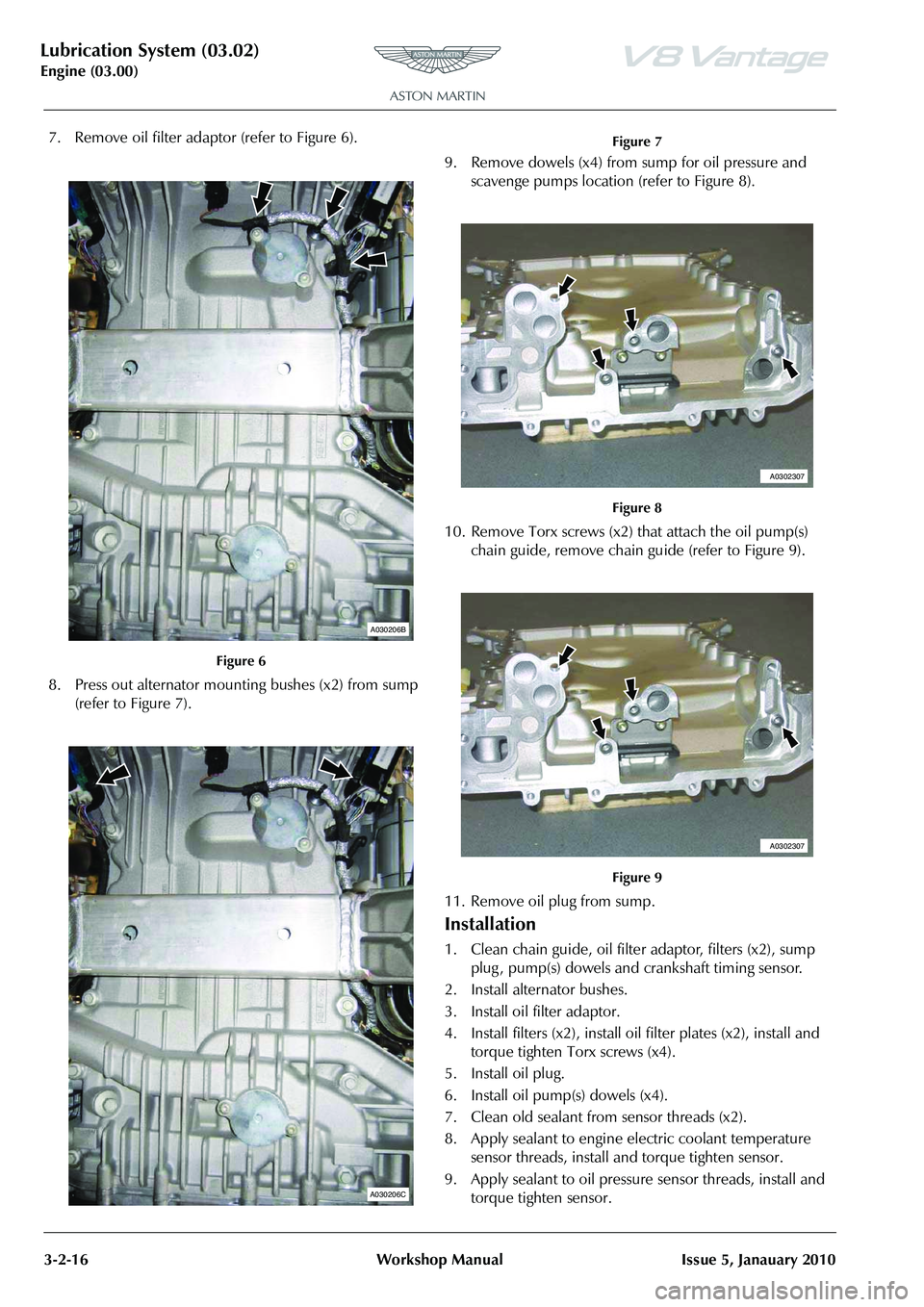
7. Remove oil filter adaptor (refer to Figure 6).
8. Press out alternator mounting bushes (x2) from sump (refer to Figure 7). 9. Remove dowels (x4) from
sump for oil pressure and
scavenge pumps location (refer to Figure 8).
10. Remove Torx screws (x2) that attach the oil pump(s)
chain guide, remove chain gu ide (refer to Figure 9).
11. Remove oil plug from sump.
Installation
1. Clean chain guide, oil filter adaptor, filters (x2), sump plug , pump(s) dowels and crankshaft timing sensor.
2. Install alternator bushes.
3. Install oil filter adaptor.
4. Install filters (x2), install oil filter plates (x2), install and
torque tighten Torx screws (x4).
5. Install oil plug.
6. Install oil pump(s) dowels (x4).
7. Clean old sealant from sensor threads (x2).
8. Apply sealant to engine electric coolant temperature sensor threads, install and torque tighten sensor.
9. Apply sealant to oil pressure sensor threads, install and torque tighten sensor.
Figure 6
A030206B
A030206C
Figure 7
Figure 8
Figure 9
A0302307
A0302307