brake light ASTON MARTIN V8 VANTAGE 2010 Workshop Manual
[x] Cancel search | Manufacturer: ASTON MARTIN, Model Year: 2010, Model line: V8 VANTAGE, Model: ASTON MARTIN V8 VANTAGE 2010Pages: 947, PDF Size: 43.21 MB
Page 3 of 947
Contents
Issue 5, January 2010 Workshop Manual 0-0-3
V8 Vantage Workshop Manual
Contents
IntroductionWelcome .............................................................. 0-0-6
Safety Precautions ................................................. 0-0-7
Lifting and Jacking ................................................. 0-0-9
Vehicle Recovery ................................................ 0-0-10
Vehicle Identification Number ............................ 0-0-11
Body System (01.00) Body Structure (01.01) .......................................... 1-1-4
Front End System (01.02) ...................................... 1-2-1
Body Closures (01.03) ........................................... 1-3-1
Interior Trim (01.05) ............................................. 1-4-1
Exterior Trim (01.08) ............................................. 1-8-1
Mirrors (01.09) ...................................................... 1-9-1
Seating (01.10).................................................... 1-10-1
Glass, Frame and Mechanism (01.11) .................. 1-11-1
Instrument Panel (IP) (01.12) . .............................. 1-12-1
Handles and Lock Mechanisms (01.14) ............... 1-14-1
Wipers and Washer System (01.16)..................... 1-16-1
Convertible Roof and Roof Opening
Subsystem (01.17)................ ...............................1-17-1
Bumpers (01.19) ................................................. 1-19-1
Restraining Devices (01.20) .... ............................. 1-20-1
Frame and Mounting (02.00) Subframes (02.03) ................................................. 2-1-2
Engine System (03.00) Engine Assembly....................................................3-0-3
Engine Structure (03.01)........................................ 3-1-1
Lubrication System (03.02).................................... 3-2-1
Cooling System (03.03) ......................................... 3-3-1
Fuel Charging System (03.04) ................................ 3-4-1
Accessory Drive System (03.05)............................. 3-5-1
Engine Cranking System (03. 06) ............................ 3-6-1
Valve Train (03.09) ............................................... 3-9-1
Engine Sealing (03.10)......................................... 3-10-1
Power Conversion (03.11)................................... 3-11-1
Evaporative Emissions (03.13) ............................. 3-11-1
Engine Management System (0 3.14).................... 3-14-1
Throttle Control (03.16) ...... ................................ 3-16-1
Foot Operated Control (03.18)............................ 3-18-1
Suspension (04.00) Road Wheel Alignment (04.00) ............................. 4-0-2
Front Suspension (04.01)....................................... 4-1-1
Rear Suspension (04.02)........................................ 4-2-1
Shock Absorber System (04.03) ............................. 4-3-1
Road Wheels and Tyres (04.04) ............................ 4-4-1
Driveline (05.00) Driveshaft (05.01) ................................................. 5-1-2
Halfshafts (05.05) .................................................. 5-2-1 Brake System (06.00)
Front Disc Brake (06.03) ....................................... 6-3-2
Rear Disc Brakes (06.04) ....................................... 6-4-1
Hand Brake (06.05) .............................................. 6-5-1
Brake Actuation System (06.06 ) ............................ 6-6-1
Power Brake System (06.07) ................................. 6-7-1
Anti-lock Braking System (06.09)........................... 6-9-1
Transmission (07.00) Transmission Cooling (07.02) ................................ 7-0-2
Manual Transmission (07.03) ................................ 7-3-1
Automatic Control System (07.05)......................... 7-5-1
Manual Control System (07.06) ............................. 7-6-1
Automatic Shifting Subsytem (07.11) .................. 7-11-1
Clutch (08.00) Clutch Controls (08.02) ......................................... 8-1-2
Exhaust (09.00) Exhaust Overview ................................................. 9-1-2
Silencer Assembly (09.01) ..................................... 9-1-3
Pipes and Supports (09.03) ................................... 9-2-1
Exhaust Protection (09.04) .................................... 9-3-1
Fuel (10.00) Fuel Tank and Lines (10.01) ................................ 10-1-2
Steering (11.00) Steering Gear (11.01) .......................................... 11-1-2
Power Steering (11.02)........................................ 11-2-1
Steering Column (11.04) ..................................... 11-4-1
Steering Column Switches (1 1.05) ....................... 11-5-1
Steering Wheel (11.06) ....................................... 11-6-1
Climate Control (12.00) Body Ventilation system (12.01) .......................... 12-1-2
Heater System (12.02) ........................................ 12-2-1
Air Conditioning (A/C) System (12.03) ................. 12-3-1
Information, Gauge and Warning (13.00) Instrument Cluster (13.01) .................................. 13-1-2
Power Supply (14.00) Battery System (14.01) ........................................ 14-1-2
Alternator and Regulator System (14.02) ............. 14-2-1
Vehicle Entertainment (15.00) Audio System (15.01)................................ ..........15-1-2
Antenna (15.02).................................................. 15-2-1
Vacuum Distribution (16.00) Body Vacuum System (16.01) ............................. 16-1-2
Lighting (17.00) Front Lights (17.01) ............................................. 17-1-2
Interior Lighting (17.02) ...................................... 17-2-1
Rear Lights (17.03) .............................................. 17-3-1
Lighting Mechanisms (17.04). .............................. 17-4-1
Page 10 of 947
Vehicle Recovery
0-0-10 Workshop Manual Issue 5, January 2010
Vehicle Recovery
General
Preferred method of vehicle recovery is by flat bed
transporter.
The towing eye is primarily for emergency use when towing
for short distances, e.g. removing vehicle if it is causing an
obstruction or winching vehicl e onto a flatbed transporter.
If moving this vehicle in such a situation, install the towing
eye to the bracket in the lower grille aperture.
Transporting
If vehicle is to be transported on a trailer or flat bed
transporter the handbrake must be applied and the road
wheels must be chocked.
Suspended Towing
Take care when using 'spectacle frame' type towing
equipment that the towing device is well clear of front or
rear apron. Body damage may occur if vehicle passes over
uneven road surfaces.
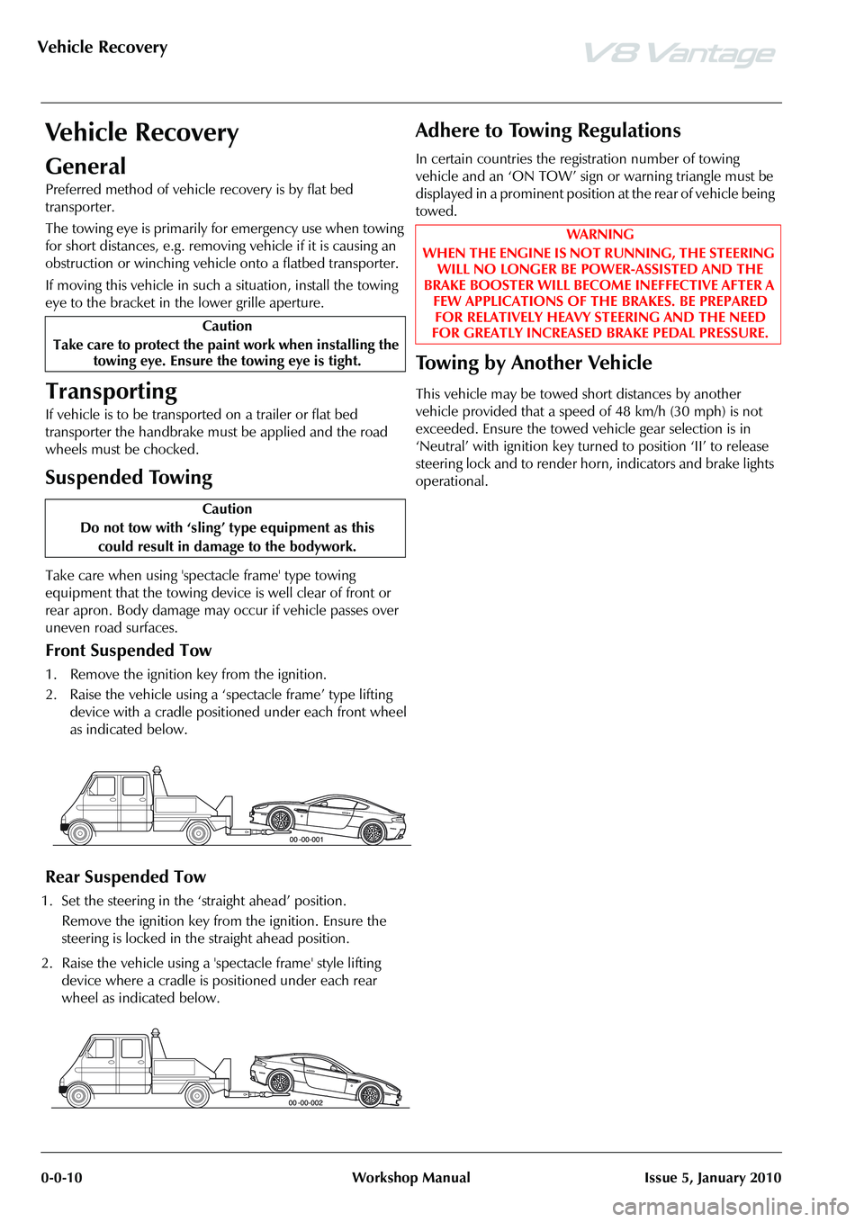
Front Suspended Tow
1. Remove the ignition key from the ignition.
2. Raise the vehicle using a ‘spectacle frame’ type lifting device with a cradle positioned under each front wheel
as indicated below.
Rear Suspended Tow
1. Set the steering in the ‘straight ahead’ position.
Remove the ignition key from the ignition. Ensure the
steering is locked in the straight ahead position.
2. Raise the vehicle using a 'spectacle frame' style lifting device where a cradle is positioned under each rear
wheel as indicated below.
Adhere to Towing Regulations
In certain countries the regi stration number of towing
vehicle and an ‘ON TOW’ sign or warning triangle must be
displayed in a prominent position at the rear of vehicle being
towed.
To w i n g b y A n o t h e r V e h i c l e
This vehicle may be towed short distances by another
vehicle provided that a speed of 48 km/h (30 mph) is not
exceeded. Ensure the towed vehicle gear selection is in
‘Neutral’ with ignition key turned to position ‘II’ to release
steering lock and to render hor n, indicators and brake lights
operational.
Caution
Take care to protect the paint work when installing the towing eye. Ensure the towing eye is tight.
Caution
Do not tow with ‘sling’ type equipment as this
could result in damage to the bodywork.
WAR NI NG
WHEN THE ENGINE IS NOT RUNNING, THE STEERING WILL NO LONGER BE POWER-ASSISTED AND THE
BRAKE BOOSTER WILL BECOME INEFFECTIVE AFTER A FEW APPLICATIONS OF TH E BRAKES. BE PREPARED
FOR RELATIVELY HEAVY STEERING AND THE NEED
FOR GREATLY INCREASED BRAKE PEDAL PRESSURE.
Page 456 of 947
Road Wheels and Tyres (04.04)
Suspension (04.00)4-4-6 Workshop Manual May 2007
Ty r e D a m a g e
Vehicle vibrations Tyres and wheels mismatched Install correct tyre and wheel combination.
Inflation pressure too high or too lo w Correct pressure to specification
Uneven tyre wear Refer to Diagnosis and Testing .
Out-of-balance wheel, tyre, wheel hub
or disc assembly Determine the out-of-balance component and
balance or install a new part.
Damaged or distorted wheel from road
impact hazard or incorrect handling Install a new wheel.
Excessive radial runout Install a new wheel or tyre. Check for incorrect wheel and tyre specifications.
Excessive lateral runout Install a new wheel or tyre.
Incorrectly seated tyre Remount the tyre.
Loose wheel mountings - damaged
wheel studs, wheel nuts, worn or
broken wheel hub face or foreign
material on mounting faces Tighten or install new parts. Clean mounting
surfaces.
Defective wheel bearings Install a new bearing set.
Brake disc imbalance
Water in tyres Remove water.
Loose engine or transmission mounts Install new mount nuts / install new mounts.
Incorrect front end alignment Align front end.
Loose or worn driveline or suspension
parts Repair or install new parts.
Excessive driveshaft runout or
imbalance Install a new driveshaft.
Worn or damaged flexible drive joint Install a new driveshaft.
Damaged wheel hub stud
threads Sliding wheel across the wheel studs
during installation. Loose wheel nuts
Install new wheel studs.
Broken wheel studs Loose or over tightened wheel nuts Install new wheel studs.
Corrosion and contamination
streaks from the wheel hub
wheel stud holes Loose wheel nuts Check complete assembly. Install new parts.
Damaged wheel nuts Loose wheel assembly Install new wheel nuts.
Over-tightened wheel nuts Install new wheel nuts.
Frozen wheel nuts Corrosion or galling If corrosion is light, wire brush away corrosion.
If corrosion is excessive install new wheel studs
and wheel nuts.
SymptomPossible Source(s):Action(s)
SymptomDescription
Age Deterioration Cracking and crazing of the tread and side wall rubber, sometimes accompanied by carcass
deformation. An indication that the tyres have been in service for a very long time.
Neglected Cut Damage through accidental cuts or penetrations will extend in use due to continued flexing and /
or ingress of moisture and road matter.
Impact Fracture Resultant damage from impact fractures is not always visible externally and, therefore, as a safety
precaution the tyre should be removed and examined.
Casing fracture caused by severe localized impact through driving over kerbs, hitting potholes
and / or objects in the road.
A double fracture caused by crushing the side wall of the tyre between an object and the rim
flange.
In both instances, such damage can lead to sudd en and dangerous tyre deflation some time after
the impact occurred.
Page 484 of 947
Hand Brake (06.05)
Brake Systems (06.00)6-5-2 Workshop Manual May 2007
Maintenance
RH/LH Handbrake Caliper-Renew
Removal
1. Raise vehicle on ramp.
2. Remove road wheel/s.
3. Ensure handbrake leve r is fully released.
4. Release handbrake adjustment (both sides).
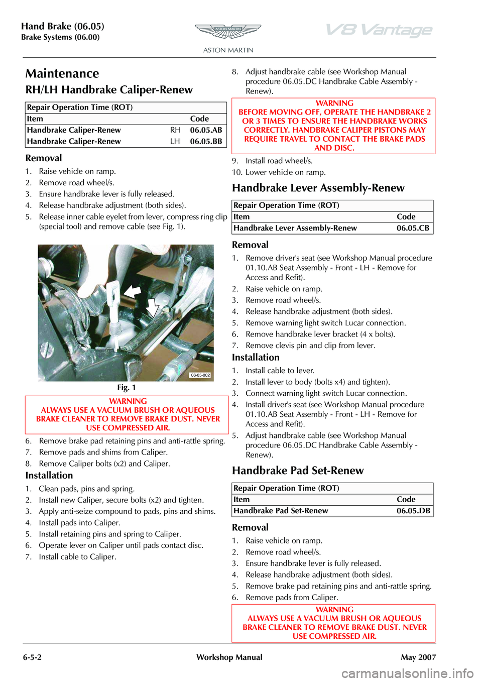
5. Release inner cable eyelet from lever, compress ring clip (special tool) and remove cable (see Fig. 1).
6. Remove brake pad retaining pins and anti-rattle spring.
7. Remove pads and shims from Caliper.
8. Remove Caliper bolts (x2) and Caliper.
Installation
1. Clean pads, pins and spring .
2. Install new Caliper, secu re bolts (x2) and tighten.
3. Apply anti-seize compound to pads, pins and shims.
4. Install pads into Caliper.
5. Install retaining pins and spring to Caliper.
6. Operate lever on Caliper until pads contact disc.
7. Install cable to Caliper. 8. Adjust handbrake cable (see Workshop Manual
procedure 06.05.DC Handbrake Cable Assembly -
Renew).
9. Install road wheel/s.
10. Lower vehicle on ramp.
Handbrake Lever Assembly-Renew
Removal
1. Remove driver's seat (see Workshop Manual procedure 01.10.AB Seat Assembly - Front - LH - Remove for
Access and Refit).
2. Raise vehicle on ramp.
3. Remove road wheel/s.
4. Release handbrake adjustment (both sides).
5. Remove warning light switch Lucar connection.
6. Remove handbrake lever bracket (4 x bolts).
7. Remove clevis pin and clip from lever.
Installation
1. Install cable to lever.
2. Install lever to body (bolts x4) and tighten).
3. Connect warning light switch Lucar connection.
4. Install driver's seat (see Workshop Manual procedure 01.10.AB Seat Assembly - Front - LH - Remove for
Access and Refit).
5. Adjust handbrake cable (see Workshop Manual procedure 06.05.DC Handbrake Cable Assembly -
Renew).
Handbrake Pad Set-Renew
Removal
1. Raise vehicle on ramp.
2. Remove road wheel/s.
3. Ensure handbrake lever is fully released.
4. Release handbrake adjustment (both sides).
5. Remove brake pad retaining pins and anti-rattle spring.
6. Remove pads from Caliper.
Repair Operation Time (ROT)
06-05-002
WAR NI NG
BEFORE MOVING OFF, OPERATE THE HANDBRAKE 2
OR 3 TIMES TO ENSURE THE HANDBRAKE WORKS CORRECTLY. HANDBRAKE CALIPER PISTONS MAY REQUIRE TRAVEL TO CONTACT THE BRAKE PADS
AND DISC.
Repair Operation Time (ROT)
ItemCode
Handbrake Lever Assembly-Renew 06.05.CB
Repair Operation Time (ROT)
ItemCode
Handbrake Pad Set-Renew 06.05.DB
WAR NI NG
ALWAYS USE A VACUUM BRUSH OR AQUEOUS
BRAKE CLEANER TO REMOVE BRAKE DUST. NEVER USE COMPRESSED AIR.
Page 485 of 947
Hand Brake (06.05)
Brake Systems (06.00)
May 2007 Workshop Manual 6-5-3
7. Remove Calipers bolts (x 4) and move Caliper aside.
Installation
1. Clean pins, springs, Caliper slide pins and pistons.
2. Retract pistons into Calipers.
3. Install Calipers and bolts (x2) to knuckles and tighten.
4. Apply anti-seize compound to pads, pins, and slide pins.
5. Install pads into Caliper.
6. Install retaining pins and springs to Caliper.
7. Operate lever on Caliper until pads contact discs.
8. Adjust handbrake cable (see Workshop Manual
procedure 06.05.DC Handbrake Cable Assembly -
Renew).
9. Install road wheel/s.
10. Lower vehicle on ramp.
Handbrake Cable Assembly-Adjust
1. Ensure handbrake is fully released.
2. Raise vehicle on ramp.
3. Check condition of handbrake cable.
4. Release handbrake cable adjustment (both sides).
5. Adjust cable equally at each Caliper to achieve 4 clicks at lever.
6. Check handbrake is not binding.
7. Lower vehicle on ramp.
8. Ensure warning light is off when handbrake lever is released.
9. Ensure for correct operation of handbrake.
Handbrake Cable Assembly-Vehicle Set-
Renew
Removal
1. Remove driver's seat (see Workshop Manual procedure
01.10.AB Seat Assembly - Front - LH - Remove for
Access and Refit).
2. Raise vehicle on ramp. 3. Remove road wheel/s.
4. Remove exhaust rear sile
ncer box (see Workshop
Manual procedure 09.00.KB Silencer and Bypass Valve
Assembly - Renew).
5. Remove rear heat shield bolts (x4) and clips (x2).
6. Release cable adjustments (both sides).
7. Remove handbrake bracket to access clevis pin and clip and disconnect from lever (see Workshop Manual
procedure 06.05.CB Handbrake Lever Assembly -
Renew).
8. Unclip cable in the cabin.
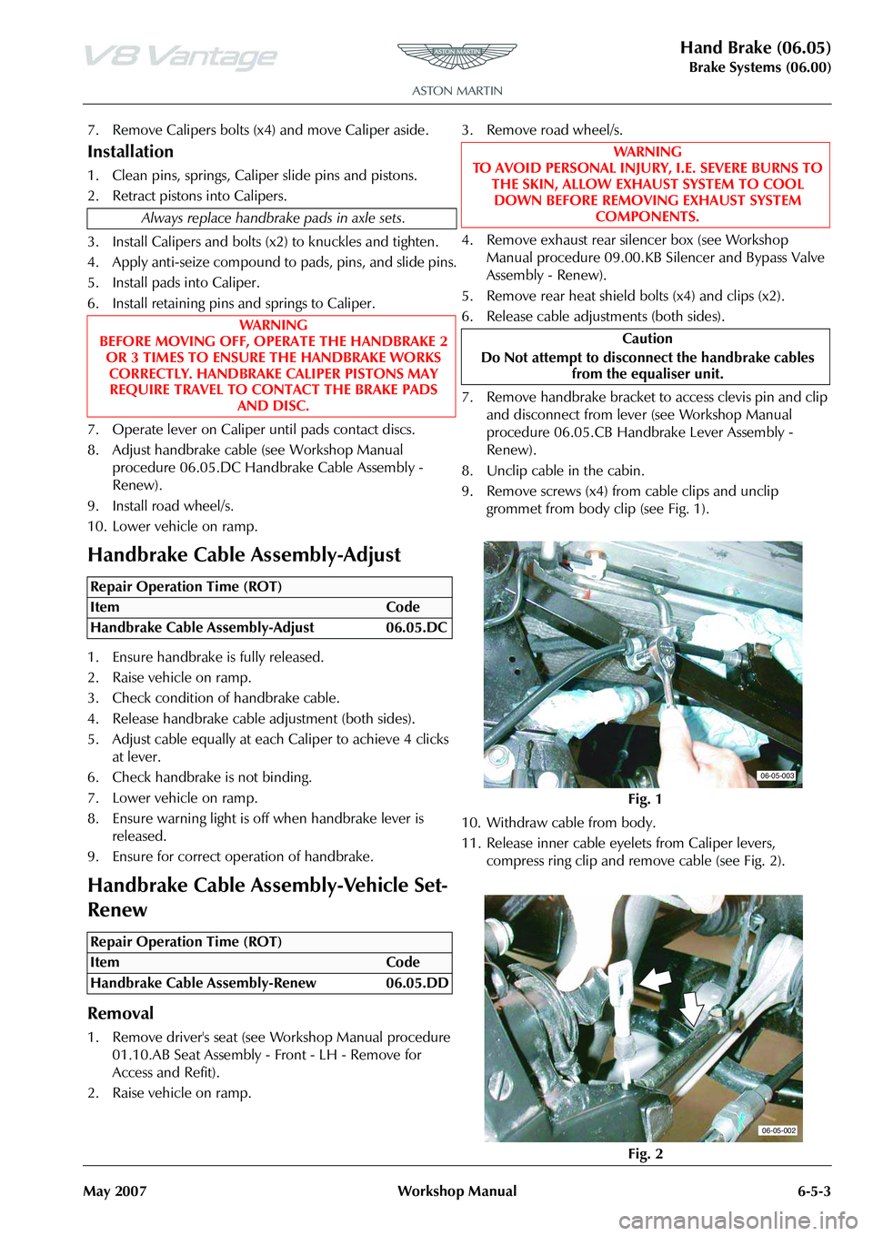
9. Remove screws (x4) from cable clips and unclip grommet from body clip (see Fig. 1).
10. Withdraw cable from body.
11. Release inner cable eyelets from Caliper levers, compress ring clip and remove cable (see Fig. 2).
Always replace handbrake pads in axle sets.
WA R N I N G
BEFORE MOVING OFF, OPERATE THE HANDBRAKE 2 OR 3 TIMES TO ENSURE THE HANDBRAKE WORKS
CORRECTLY. HANDBRAKE CALIPER PISTONS MAY REQUIRE TRAVEL TO CONTACT THE BRAKE PADS AND DISC.
Repair Operation Time (ROT)
Repair Operation Time (ROT)
WA R N I N G
TO AVOID PERSONAL INJURY, I.E. SEVERE BURNS TO
THE SKIN, ALLOW EXHAUST SYSTEM TO COOL DOWN BEFORE REMOVING EXHAUST SYSTEM COMPONENTS.
Caution
Do Not attempt to disconne ct the handbrake cables
from the equaliser unit.
Fig. 1
Fig. 2
06-05-003
06-05-002
Page 502 of 947
Power Brake System (06.07)
Brake System (06.00)6-7-2 Workshop Manual May 2007
Specifications
Maintenance
Brake Booster-RHD-Renew
Removal
1. Remove brake master cylind er (see Workshop Manual
procedure 06.06.EB Brake Master Cylinder Assembly
Renew).
2. Remove oil dipstick.
3. Remove vacuum hose.
4. Disconnect multiplugs (x2).
5. Remove pedal cover.
6. Remove clevis pin and clip.
7. Remove servo securing nuts (x4).
8. Remove servo assembly.
9. Remove brake light switch.
Installation
1. Install brake light switch.
2. Install servo assembly.
3. Install servo retaining nuts (x4) (torque).
4. Install clevis pin and clip.
5. Install pedal cover.
6. Connect multiplugs (x2).
7. Install vacuum hose.
8. Install dipstick. 9. Install brake master cylinder (see Workshop Manual
procedure 06.06.EB Brake Master Cylinder Assembly
Renew).
Brake Booster-LHD-Renew
Removal
1. Move drivers seat fully rearward.
2. Remove clevis pin and clip.
3. Remove booster securing nuts (x4).
4. Remove corner cross brace.
5. Move expansion tank aside for access (bolt x1, nut x1,
hose clips x2, multiplug x1).
6. Remove vacuum hose move aside.
7. Remove bolts (x2) from clutch pipe bracket and move aside.
8. Disconnect clutch reservoir feed pipe.
9. Disconnect multiplugs (x4).
10. Disconnect brake pipes from master cylinder (move aside).
11. Remove booster assembly.
12. Split components.
13. Remove reservoir securing screw (for access to securing nut).
14. Remove master cylinder from booster (nuts x2).
15. Re-fit components.
16. Install master cylinder to booster (nuts x2).
17. Install reservoir securing screw.
Torque Figures
DescriptionNm.lb. / ft.
Brake Booster Mount 21-24 15.5-18
Repair Operation Time (ROT)
Repair Operation Time (ROT)
ItemCode
Brake Booster-Renew 06.07.AC
WAR NI NG
AVOID SKIN / EYE CONTACT OR INGESTION OF
BRAKE FLUID. IF SKIN OR EYES ARE SPLASHED WITH BRAKE FLUID, RINSE THE AFFECTED AREA
IMMEDIATELY WITH PLENTY OF WATER AND OBTAIN MEDICAL ATTENTION. IF BR AKE FLUID IS INGESTED,
OBTAIN IMMEDIATE MEDICAL ATTENTION.
WAR NI NG
BRAKE FLUID IS HYGROSCOPIC. IF KEPT IN OPENED CONTAINERS IT WILL ABSORB WATER VAPOUR. USE
ONLY BRAKE FLUID FROM FRESHLY OPENED
CONTAINERS WHEN TOPPING-UP THE BRAKE FLUID RESERVOIR.
Caution
Brake fluid must not be allowed to contact the vehicle
paint work. Remove spilt brake fluid from the paint work
by rinsing away with running water.
Caution
Always plug pipe ends to prevent ingress of dirt or
moisture into the system.
Caution
Always plug pipe ends to prevent ingress of dirt or
moisture into the system.
Page 507 of 947
Anti-lock Braking System (ABS) (06.09)
Brake system (06.00)
Issue 4, November 2008 Workshop Manual 6-9-1
Brake system (06.00)
Anti-lock Braking System (ABS) (06.09)
The anti-lock braking system (ABS) is a four-channel system
having independent inputs from all four-wheel speed
sensors.
The ABS module, monitors signals from the sensors to
calculate, brake slip and the acceleration / deceleration of
individual wheels. When the brake pedal is depressed, and
the ABS module detects incipient wheel lock-up from the
incoming signals, it triggers the re-circulation pump inside
the module’s hydraulic modulator, and the solenoid valves
for the wheel(s) concerned. Brake pressure, is then
modulated to increase / decrease or remain constant at the
wheel(s) concerned until whee l lock-up is eliminated. The
ABS provides self-diagnosis and any malfunction within the
system will be indicated to the dr iver by the illumination of
the brake warning light and ‘ABS FAULT’ displayed in the
message centre right. Should a fault develop within the ABS,
the brake system will operate conventionally and with the
same standard of performanc e as a vehicle not equipped
with ABS.
Dynamic Stability Control
Dynamic Stability Control (DSC ) is a closed-loop system
designed to enhance driving safety by improving vehicle
handling when the tyres are at the limits of their grip
capabilities. This is achieved through instantaneous,
electronically controlled, reduction of engine torque and
strategic application of the brakes at individual wheels.
By using the principle that by controlling the brakes
individually it is possible, to an extent, to steer the vehicle.
This principle can be used to enhance driving safety by
correcting the vehicle’s yaw moment (turning force), when
the vehicle fails to follow th e driver’s steering inputs.
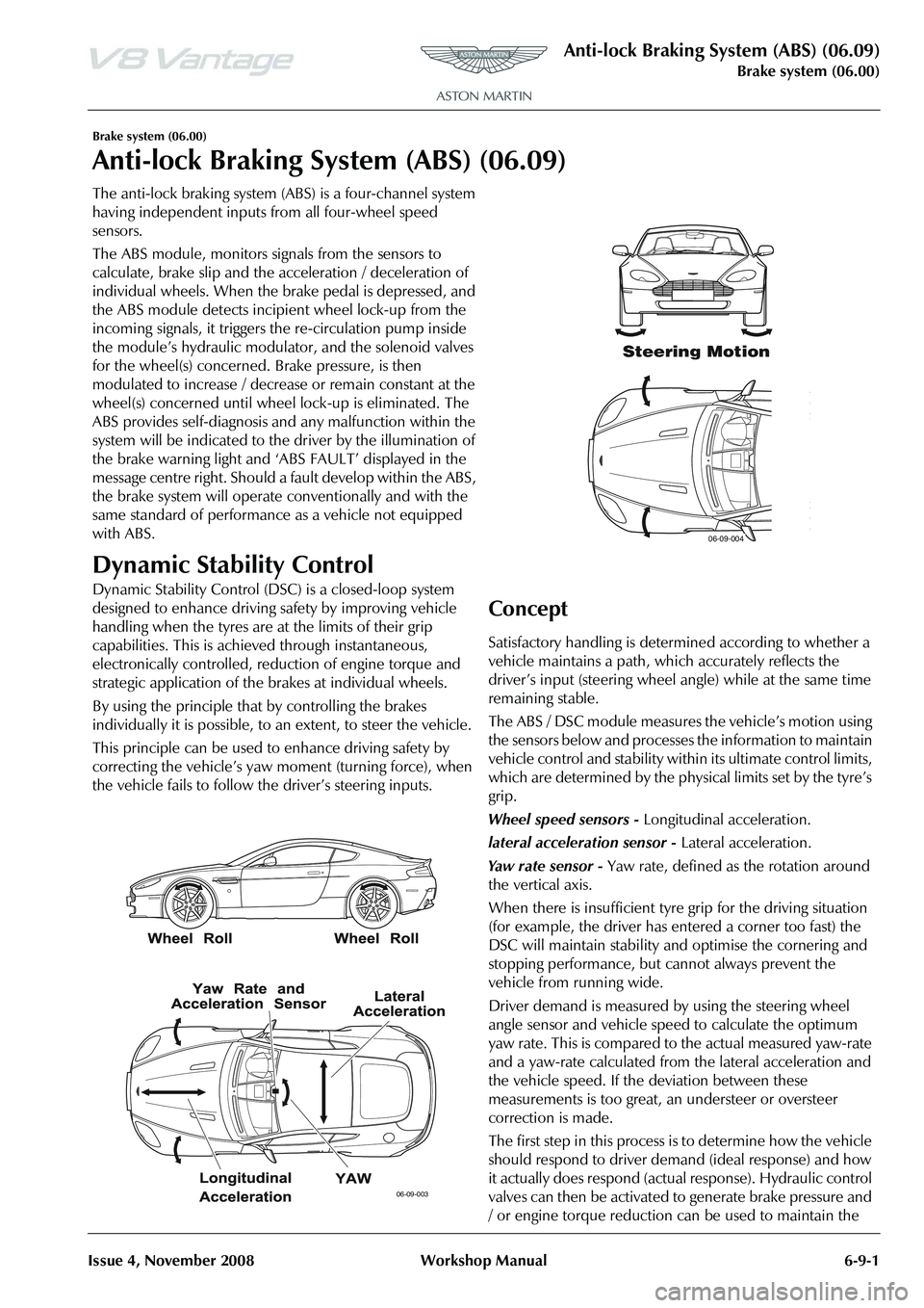
Concept
Satisfactory handling is determined according to whether a
vehicle maintains a path, wh ich accurately reflects the
driver
Page 508 of 947
Anti-lock Braking System (ABS) (06.09)
Brake system (06.00)
6-9-2 Workshop Manual Issue 4, November 2008
difference between the ideal and actual response within a
tolerance band. This directly influences the forces on the
tires to generate a corrective yaw moment to reduce the side
forces of the tires where appropriate
System Overview
The DSC system embraces capabilities far beyond that of
ABS, or ABS and traction control combined, while relying on
the components of these systems. It also incorporates these
additional sensors for measur ing the vehicle’s motion and
brake system pressure:
Ya w r a t e s e n s o r - located centrally on the transmission
tunnel.
Lateral acceleration sensor - integrated with the yaw rate
sensor.
Steering angle sensor - located on the upper steering
column.
Pressure transducer - located on master cylinder.
The ABS / DSC module supports data exchange with other
vehicle electronic systems via the CAN network; the module
also enables diagnostic interrogation using WDS.
The following components register driver demand and the
ABS / DSC module processes their signals as a basis for
defining an ideal response:
PCM - position of accelerator pedal.
Brake master cylinder pressure transducer - driver’s
braking effort.
Steering angle sensor - position of steering wheel.
There are many supplementary parameters also included in
the processing calculations these include the coefficient of
friction and vehicle speed. The ABS / DSC module monitors
these factors based on signals transmitted by the sensors for:
• Wheel speed
• Lateral acceleration
• Brake pressure
• Yaw rate
Using these parameters, the function of the ABS / DSC
module is to determine the current vehicle status based on
the yaw-rate signal and the slip as estimated by the ABS /
DSC module. It then maintains the vehicle response within
a tolerance of the ‘normal’ behaviour, which is easily
controlled by the driver.
In order to generate the desired yaw behaviour the ABS /
DSC module controls the selected wheels using the ABS
hydraulic system and engine control system. In the event of
engine intervention, the ABS / DSC module calculates the
torque which should be supplied by the engine to the
wheels, and relays this request signal to the PCM which
implements the torque request.
The PCM receives signals from the DSC system via the CAN
bus and reduces engine torque as follows:
• The throttle is positioned to provide the requested engine target torque. • During the transient phase of torque reduction caused by
mechanical and combustion delays, other alternative
torque reduction methods are used to provide a quicker
response.
• The ignition is retarded and / or the fuel is cut-off at the injectors at selected cylinders.
• Ignition and fuelling are reinstated when the engine torque reaches the requested value
Operation Summary
• DSC is switched ‘ON’ when the engine is started
• When the system is operating , the DSC light in the instrument cluster will flash, at the rate of twice a second
• DSC can be switched ‘OFF / ON’ by pressing the DSC switch
• The DSC light in the instru ment cluster will illuminate
continuously when the system is switched ‘Off’.
• ‘DSC OFF’ will be displayed in the message centre right to indicate the system has been switched ‘OFF’
• A malfunction in the traction control system will be indicated to the driver by the following:
• The DSC light in the instru ment cluster will illuminate
continuously
• The message ‘DSC NOT AVAILABLE’ will be displayed in the message centre right
• If vehicle speed control is engaged it will automatically disengage when traction control is operating .
Traction Control
Traction control is a function of DSC, and is operated in
association with DSC. Traction control prevents excessive
wheel-spin at standing starts, or during acceleration. Wheel-
spin is usually caused by ex cessive use of the accelerator
pedal, or slippery, loose or bumpy road surfaces. To prevent
excessive wheel-spin and mainta in vehicle stability such
situations are overcome by the intervention of the traction
control system by:
• Braking the driven-wheel when it starts to slip
• And / or adapting the engine torque to a level corresponding to the traction available on the road
surface.
Functional Description
Traction control uses the ABS electronic and mechanical /
hydraulic hardware with additional valves to control the
braking pressure at the calipe rs. An engine interface also
enables the engine to respond to torque reduction requests
from the traction control. As with ABS, the signals from the
wheel-speed sensors are supplied to the ABS module, where
they are used to calculate the wheel-slip of the individual
wheels. Traction control intervention is initiated if the slip at
one of the wheels is excessive.
Page 654 of 947
Instrument Cluster (13.01)
Information, Gauge and Warning (13.00)
May 2007 Workshop Manual 13-1-3
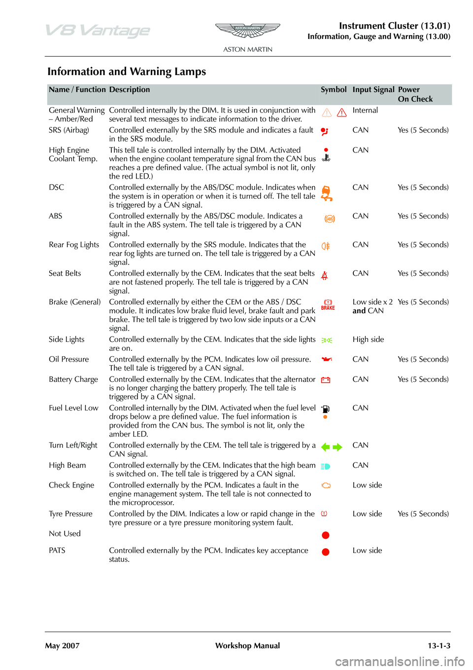
Information and Warning Lamps
Name / FunctionDescriptionSymbolInput SignalPower
On Check
General Warning
– Amber/Red Controlled internally by the DIM. It is used in conjunction with
several text messages to indicate information to the driver. Internal
SRS (Airbag) Controlled externally by the SRS module and indicates a fault in the SRS module. CAN Yes (5 Seconds)
High Engine
Coolant Temp. This tell tale is controlled internally by the DIM. Activated
when the engine coolant temperature signal from the CAN bus
reaches a pre defined value. (The
actual symbol is not lit, only
the red LED.) CAN
DSC Controlled externally by the ABS/DSC module. Indicates when the system is in operation or when it is turned off. The tell tale
is triggered by a CAN signal. CAN Yes (5 Seconds)
ABS Controlled externally by th e ABS/DSC module. Indicates a
fault in the ABS system. The tell tale is triggered by a CAN
signal. CAN Yes (5 Seconds)
Rear Fog Lights Controlled externally by the SRS module. Indicates that the
rear fog lights are turned on. The tell tale is triggered by a CAN
signal. CAN Yes (5 Seconds)
Seat Belts Controlled externally by the CEM. Indicates that the seat belts are not fastened properly. The tell tale is triggered by a CAN
signal. CAN Yes (5 Seconds)
Brake (General) Controlled externally by either the CEM or the ABS / DSC module. It indicates low brake fluid level, brake fault and park
brake. The tell tale is triggered by two low side inputs or a CAN
signal. Low side x 2
and
CAN Ye s ( 5 S e c o n d s )
Side Lights Controlled externally by th e CEM. Indicates that the side lights
are on. High side
Oil Pressure Controlled exte rnally by the PCM. Indicates low oil pressure.
The tell tale is triggered by a CAN signal. CAN Yes (5 Seconds)
Battery Charge Controlled externally by th e CEM. Indicates that the alternator
is no longer charging the battery properly. The tell tale is
triggered by a CAN signal. CAN Yes (5 Seconds)
Fuel Level Low Controlled internally by the DIM. Activated when the fuel level drops below a pre defined value. The fuel information is
provided from the CAN bus. The symbol is not lit, only the
amber LED. CAN
Turn Left/Right Controlled externally by th e CEM. The tell tale is triggered by a
CAN signal. CAN
High Beam Controlled externally by the CEM. Indicates that the high beam is switched on. The tell tale is triggered by a CAN signal. CAN
Check Engine Controlled externally by the PCM. Indicates a fault in the engine management system. The te ll tale is not connected to
the microprocessor. Low side
Tyre Pressure Controlled by the DIM. In dicates a low or rapid change in the
tyre pressure or a tyre pressure monitoring system fault. Low side Yes (5 Seconds)
Not Used
PATS Controlled externally by the PCM. Indicates key acceptance status. Low side
Page 692 of 947
Wiring and Circuit Protection (18.01)
Electric Distribution/Electronic Control (18.00)
May 2007 Workshop Manual 18-1-3
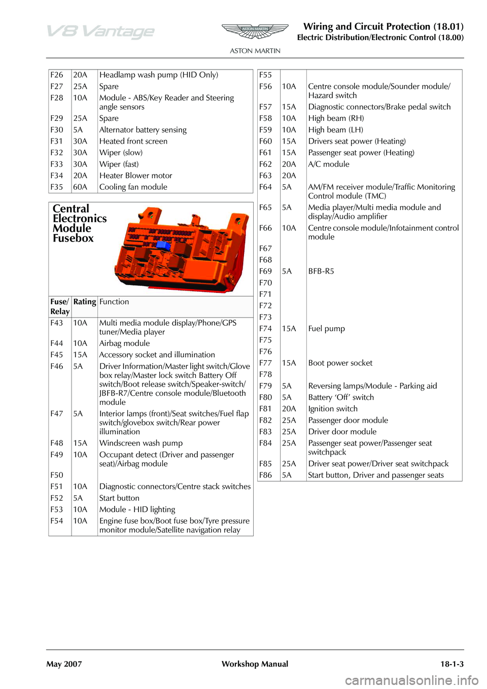
F26 20A Headlamp wash pump (HID Only)
F27 25A Spare
F28 10A Module - ABS/Key Reader and Steering angle sensors
F29 25A Spare
F30 5A Alternator battery sensing
F31 30A Heated front screen
F32 30A Wiper (slow)
F33 30A Wiper (fast)
F34 20A Heater Blower motor
F35 60A Cooling fan module
Central
Electronics
Module
Fusebox
Fuse/
RelayRatingFunction
F43 10A Multi media module display/Phone/GPS tuner/Media player
F44 10A Airbag module
F45 15A Accessory socket and illumination
F46 5A Driver Information/Master light switch/Glove box relay/Master lock switch Battery Off
switch/Boot release switch/Speaker-switch/
JBFB-R7/Centre console module/Bluetooth
module
F47 5A Interior lamps (front)/Seat switches/Fuel flap switch/glovebox switch/Rear power
illumination
F48 15A Windscreen wash pump
F49 10A Occupant detect (Driver and passenger seat)/Airbag module
F50
F51 10A Diagnostic connectors/Centre stack switches
F52 5A Start button
F53 10A Module - HID lighting
F54 10A Engine fuse box/Boot fuse box/Tyre pressure monitor module/Satellite navigation relay
F55
F56 10A Centre console module/Sounder module/
Hazard switch
F57 15A Diagnostic connectors/Brake pedal switch
F58 10A High beam (RH)
F59 10A High beam (LH)
F60 15A Drivers seat power (Heating)
F61 15A Passenger seat power (Heating)
F62 20A A/C module
F63 20A
F64 5A AM/FM receiver module/Traffic Monitoring Control module (TMC)
F65 5A Media player/Multi media module and display/Audio amplifier
F66 10A Centre console module/Infotainment control module
F67
F68
F69 5A BFB-R5
F70
F71
F72
F73
F74 15A Fuel pump
F75
F76
F77 15A Boot power socket
F78
F79 5A Reversing lamps/Module - Parking aid
F80 5A Battery ‘Off’ switch
F81 20A Ignition switch
F82 25A Passenger door module
F83 25A Driver door module
F84 25A Passenger seat power/Passenger seat switchpack
F85 25A Driver seat power/Driver seat switchpack
F86 5A Start button, Driver and passenger seats