tire ASTON MARTIN V8 VANTAGE 2010 Workshop Manual
[x] Cancel search | Manufacturer: ASTON MARTIN, Model Year: 2010, Model line: V8 VANTAGE, Model: ASTON MARTIN V8 VANTAGE 2010Pages: 947, PDF Size: 43.21 MB
Page 460 of 947
Road Wheels and Tyres (04.04)
Suspension (04.00)4-4-10 Workshop Manual May 2007
Display Unit
The display unit provides additional features when correctly
connected to a previously installed ‘Smartire’ system. The
display unit connects directly to the front of the basic
‘Smartire’ receiver and is powered from the vehicle circuits.
The display will be fully illu minated during use but will go
into ‘Energy Saver’ mode when no activity is detected.
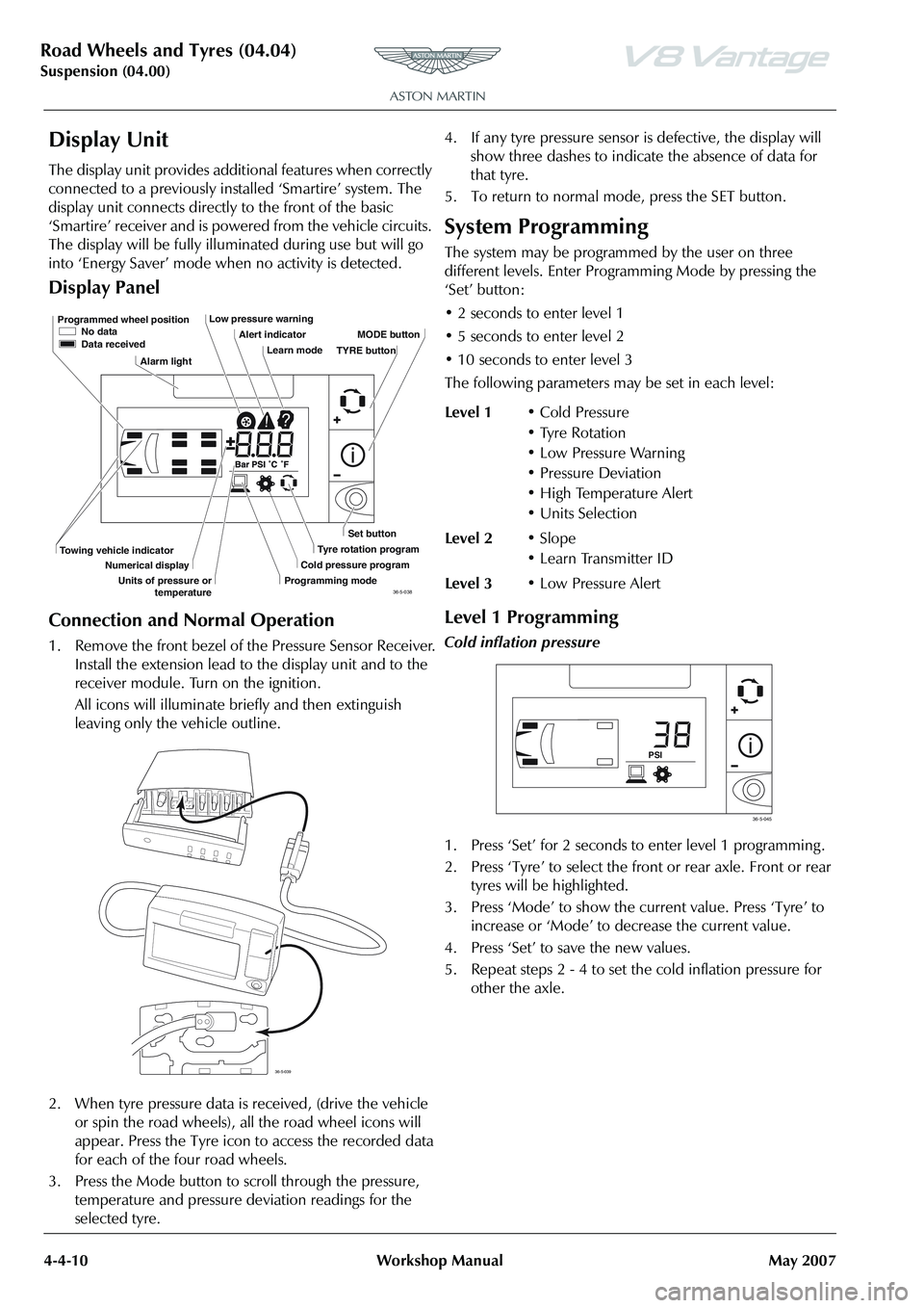
Display Panel
Connection and Normal Operation
1. Remove the front bezel of the Pressure Sensor Receiver. Install the extension lead to the display unit and to the
receiver module. Turn on the ignition.
All icons will illuminate briefly and then extinguish
leaving only the vehicle outline.
2. When tyre pressure data is received, (drive the vehicle
or spin the road wheels), all the road wheel icons will
appear. Press the Tyre icon to access the recorded data
for each of the four road wheels.
3. Press the Mode button to scroll through the pressure, temperature and pressure deviation readings for the
selected tyre. 4. If any tyre pressure sensor is defective, the display will
show three dashes to indicate the absence of data for
that tyre.
5. To return to normal mode, press the SET button.
System Programming
The system may be programmed by the user on three
different levels. Enter Progra mming Mode by pressing the
‘Set’ button:
• 2 seconds to enter level 1
• 5 seconds to enter level 2
• 10 seconds to enter level 3
The following parameters ma y be set in each level:
Level 1 Programming
Cold inflation pressure
1. Press ‘Set’ for 2 seconds to enter level 1 programming .
2. Press ‘Tyre’ to select the front or rear axle. Front or rear
tyres will be highlighted.
3. Press ‘Mode’ to show the current value. Press ‘Tyre’ to increase or ‘Mode’ to decrease the current value.
4. Press ‘Set’ to save the new values.
5. Repeat steps 2 - 4 to set the cold inflation pressure for other the axle.
Programmed wheel position No data
Data received
Alarm light Low pressure warning
Alert indicatorLearn mode MODE button
Set button
Tyre rotation program
Cold pressure program
Programming mode
Towing vehicle indicator
Numerical display
Units of pressure or temperature TYRE button
36-5-038
36-5-039
Level 1
• Cold Pressure
• Tyre Rotation
• Low Pressure Warning
• Pressure Deviation
• High Temperature Alert
•Units Selection
Level 2 •Slope
• Learn Transmitter ID
Level 3 • Low Pressure Alert
PSI
36-5-045
Page 508 of 947
Anti-lock Braking System (ABS) (06.09)
Brake system (06.00)
6-9-2 Workshop Manual Issue 4, November 2008
difference between the ideal and actual response within a
tolerance band. This directly influences the forces on the
tires to generate a corrective yaw moment to reduce the side
forces of the tires where appropriate
System Overview
The DSC system embraces capabilities far beyond that of
ABS, or ABS and traction control combined, while relying on
the components of these systems. It also incorporates these
additional sensors for measur ing the vehicle’s motion and
brake system pressure:
Ya w r a t e s e n s o r - located centrally on the transmission
tunnel.
Lateral acceleration sensor - integrated with the yaw rate
sensor.
Steering angle sensor - located on the upper steering
column.
Pressure transducer - located on master cylinder.
The ABS / DSC module supports data exchange with other
vehicle electronic systems via the CAN network; the module
also enables diagnostic interrogation using WDS.
The following components register driver demand and the
ABS / DSC module processes their signals as a basis for
defining an ideal response:
PCM - position of accelerator pedal.
Brake master cylinder pressure transducer - driver’s
braking effort.
Steering angle sensor - position of steering wheel.
There are many supplementary parameters also included in
the processing calculations these include the coefficient of
friction and vehicle speed. The ABS / DSC module monitors
these factors based on signals transmitted by the sensors for:
• Wheel speed
• Lateral acceleration
• Brake pressure
• Yaw rate
Using these parameters, the function of the ABS / DSC
module is to determine the current vehicle status based on
the yaw-rate signal and the slip as estimated by the ABS /
DSC module. It then maintains the vehicle response within
a tolerance of the ‘normal’ behaviour, which is easily
controlled by the driver.
In order to generate the desired yaw behaviour the ABS /
DSC module controls the selected wheels using the ABS
hydraulic system and engine control system. In the event of
engine intervention, the ABS / DSC module calculates the
torque which should be supplied by the engine to the
wheels, and relays this request signal to the PCM which
implements the torque request.
The PCM receives signals from the DSC system via the CAN
bus and reduces engine torque as follows:
• The throttle is positioned to provide the requested engine target torque. • During the transient phase of torque reduction caused by
mechanical and combustion delays, other alternative
torque reduction methods are used to provide a quicker
response.
• The ignition is retarded and / or the fuel is cut-off at the injectors at selected cylinders.
• Ignition and fuelling are reinstated when the engine torque reaches the requested value
Operation Summary
• DSC is switched ‘ON’ when the engine is started
• When the system is operating , the DSC light in the instrument cluster will flash, at the rate of twice a second
• DSC can be switched ‘OFF / ON’ by pressing the DSC switch
• The DSC light in the instru ment cluster will illuminate
continuously when the system is switched ‘Off’.
• ‘DSC OFF’ will be displayed in the message centre right to indicate the system has been switched ‘OFF’
• A malfunction in the traction control system will be indicated to the driver by the following:
• The DSC light in the instru ment cluster will illuminate
continuously
• The message ‘DSC NOT AVAILABLE’ will be displayed in the message centre right
• If vehicle speed control is engaged it will automatically disengage when traction control is operating .
Traction Control
Traction control is a function of DSC, and is operated in
association with DSC. Traction control prevents excessive
wheel-spin at standing starts, or during acceleration. Wheel-
spin is usually caused by ex cessive use of the accelerator
pedal, or slippery, loose or bumpy road surfaces. To prevent
excessive wheel-spin and mainta in vehicle stability such
situations are overcome by the intervention of the traction
control system by:
• Braking the driven-wheel when it starts to slip
• And / or adapting the engine torque to a level corresponding to the traction available on the road
surface.
Functional Description
Traction control uses the ABS electronic and mechanical /
hydraulic hardware with additional valves to control the
braking pressure at the calipe rs. An engine interface also
enables the engine to respond to torque reduction requests
from the traction control. As with ABS, the signals from the
wheel-speed sensors are supplied to the ABS module, where
they are used to calculate the wheel-slip of the individual
wheels. Traction control intervention is initiated if the slip at
one of the wheels is excessive.
Page 742 of 947
Fluids/Capacities
Appendix & Glossary
May 2007 Workshop Manual 20-1-3
Fluids/Capacities
Terms
Frequently used alternative names or spellings for vehicle
components mentioned in this Workshop Manual.
Capacities
Europe UK USA
Engine sump (incl. filter) 9 .5 litres 16.7 pints 10.0 Qts
Engine sump (excl. filter) 8 .5 litres 15.0 pints 9.0 Qts
Engine cooling system 12 litres 21 pints 14.4 Qts
Screen washer reservoir 2.0 litres 3.5 pints 2.2 Qts
Gearbox & Cooler 4.7 litres 7.9 pints 5.6 Qts
Final drive 2.0 litres 3.5 pints 2.2 Qts
Fuel tank 80.0 litres 17.6 galls 88.0 Qts
Recommended Fluids
Engine oil (Initial fill) Castrol Edge Sport 10w60
Do not mix Engine oil with any mineral oils.
Engine coolant 50% water, 50% OAT Coolant (Arteco Havoline XLC only)
Do not mix OAT coolant with any glycol based anti-freeze.
Gearbox oil Shell Transaxle Oil 75w90
Final drive oil Mobil 1 80w140
Brake fluid Castrol Super Response DOT4
Power steering fluid Esso Power steering Fluid
A/C Refrigerant R134A (HFC134A)
A/C Compressor oil ND8
UK EnglishUS English
Bonnet Hood
Boot Trunk
Brake Disc Rotor
Handbrake Parking Brake
Petrol Gasoline
Tyre Tire
Wing Fender
Windscreen Windshield
Sill Rocker Panel
Page 828 of 947
Electronics Training Programme
Making Calls
When connected, all calls are handsfree. Termin ate a VR session at any time by pressing the
button.
A phone number can be entered as a whole number or by two or more segments. A segment can
include up to 15 digits. An entire number can inclu de no more than 32 digits. If required a number
can also begin by saying either ‘Star’ (*), ‘Hash’ (#) or ‘Plus’ (+).
Note: Speak numbers as continuous digits. For exampl e, dictate 555-2211 as ‘5-5-5-2-2-1-1’, not ‘5-
5-5-twenty-two-eleven’.
To make a call using a whole number:
1. Press the button. When prompted, say ‘Dial Nu mber’. The system responds with
‘Number please?’.
2. Dictate the phone number as a single set of digits (without pauses between digits). The system
recites the digits heard.
3. If the number recited by the system is correct, say ‘Dial’. The system re sponds with ‘Dialling’.
To make a call using a number segment:
1. Press the button. When prompted, say ‘Dial Number’. The system responds with
‘Number please?’.
2. Dictate the first segment of the whole number (For example, say the 1st three numbers.) The system recites the numbers heard.
3. Dictate the next segment of the whole number. The system recites the numbers heard. Repeat
until you have entered the complete phone number.
4. When the complete number is recited by t he system, say ‘Dial’. The system responds:
‘Dialling’.
Note: To delete a phone number segment, say ‘Clear ’ when prompted for the next segment. The
system responds with ‘Last String Entry Cleared’, ec hoes any remaining segments, and waits for you to
dictate a new segment.
Note: To clear all phone number segments dictated so far, say ‘Clear All’ when prompted for the next
segment. The system clears all segments and returns to the ‘Number please?’ prompt.
23
Page 832 of 947
Electronics Training Programme
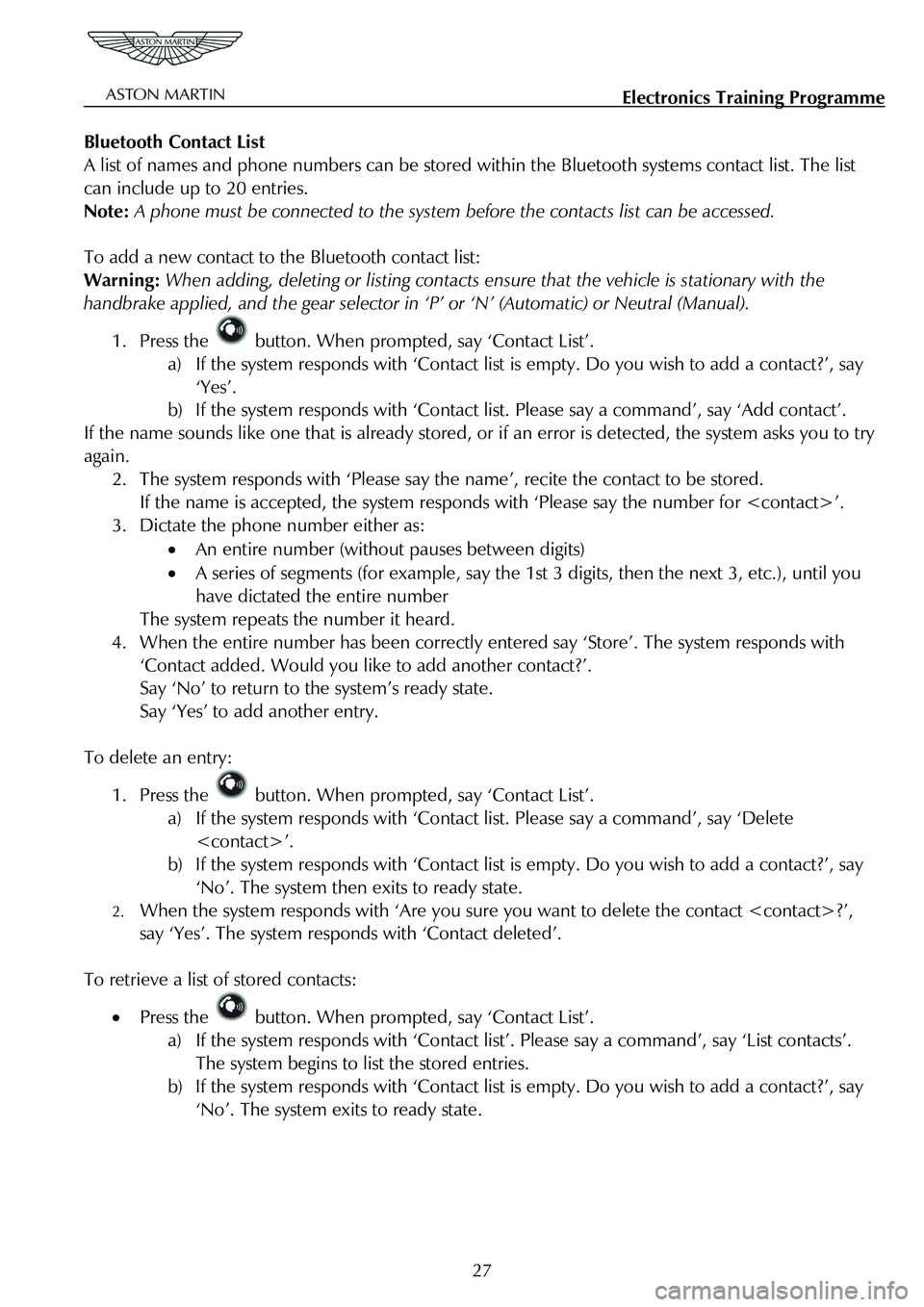
Bluetooth Contact List
A list of names and phone numbers can be stored wi thin the Bluetooth systems contact list. The list
can include up to 20 entries.
Note: A phone must be connected to the system be fore the contacts list can be accessed.
To add a new contact to the Bluetooth contact list:
Warning: When adding, deleting or listing contacts en sure that the vehicle is stationary with the
handbrake applied, and the gear selector in ‘P’ or ‘N’ (Automatic) or Neutral (Manual).
1. Press the button. When prompted, say ‘Contact List’.
a) If the system responds with ‘Contact list is empty. Do you wish to add a contact?’, say
‘Yes’.
b) If the system responds with ‘Contact li st. Please say a command’, say ‘Add contact’.
If the name sounds like one that is already stored, or if an error is detected, the system asks you to try
again.
2. The system responds with ‘Please say t he name’, recite the contact to be stored.
If the name is accepted, the system responds with ‘Please say the number for
3. Dictate the phone number either as:
• An entire number (without pauses between digits)
• A series of segments (for example, say the 1st 3 digits, then the next 3, etc.), until you
have dictated the entire number
The system repeats the number it heard.
4. When the entire number has been correctly entered say ‘Store’. The system responds with
‘Contact added. Would you like to add another contact?’.
Say ‘No’ to return to the system’s ready state.
Say ‘Yes’ to add another entry.
To delete an entry:
1. Press the button. When prompted, say ‘Contact List’.
a) If the system responds with ‘Contact list. Please say a command’, say ‘Delete
b) If the system responds with ‘Contact list is empty. Do you wish to add a contact?’, say
‘No’. The system then exits to ready state.
2. When the system responds with ‘Are you sure you want to delete the contact
say ‘Yes’. The system respon ds with ‘Contact deleted’.
To retrieve a list of stored contacts:
• Press the button. When prompted, say ‘Contact List’.
a) If the system responds with ‘Contact list ’. Please say a command’, say ‘List contacts’.
The system begins to list the stored entries.
b) If the system responds with ‘Contact list is empty. Do you wish to add a contact?’, say
‘No’. The system exits to ready state.
27
Page 854 of 947
AML EOBD System Operation Summary
Rory O’Curry Aston Martin Lagonda CONFIDENTIAL 1 May 2009
[email protected] AML EOBD Monitors 07 ROC.doc Page 8 of 43
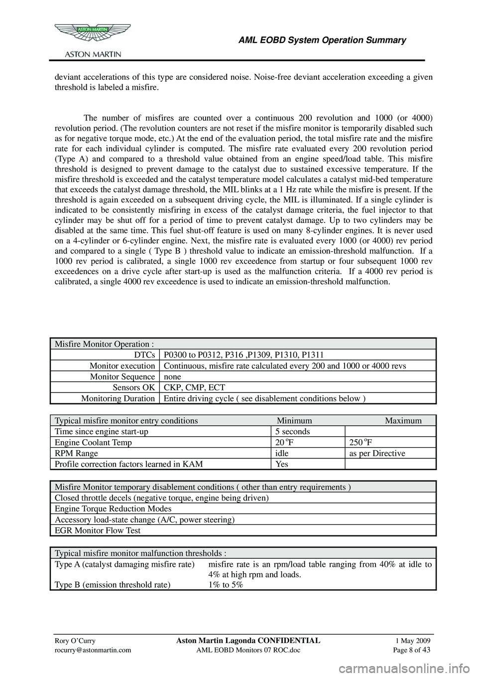
deviant accelerations of this type are considered noise. Noise-free deviant acceleration exceeding a given
threshold is labeled a misfire.
The number of misfires are counted over a continuous 200 revolution and 1000 (or 4000)
revolution period. (The revolution counters are not reset if the misfire monitor is temporarily disabled such
as for negative torque mode, etc.) At the end of the evaluation period, the total misfire rate and the misfire
rate for each individual cylinder is computed. The misfire rate evaluated every 200 revolution period
(Type A) and compared to a threshold value obtaine d from an engine speed/load table. This misfire
threshold is designed to prevent damage to the cat alyst due to sustained excessive temperature. If the
misfire threshold is exceeded and the catalyst temperature model calculates a catalyst mid-bed temperature
that exceeds the catalyst damage threshold, the MIL blinks at a 1 Hz rate while the misfire is present. If the
threshold is again exceeded on a subsequent driving cy cle, the MIL is illuminated. If a single cylinder is
indicated to be consistently misfiring in excess of the catalyst damage criteria, the fuel injector to that
cylinder may be shut off for a period of time to pr event catalyst damage. Up to two cylinders may be
disabled at the same time. This fuel shut-off feature is used on many 8-cylinder engines. It is never used
on a 4-cylinder or 6-cylinder engine. Next, the misf ire rate is evaluated every 1000 (or 4000) rev period
and compared to a single ( Type B ) threshold value to indicate an emission-threshold malfunction. If a
1000 rev period is calibrated, a single 1000 rev exceedence from startup or four subsequent 1000 rev
exceedences on a drive cycle after start-up is used as the malfunction criteria. If a 4000 rev period is
calibrated, a single 4000 rev exceedence is used to indicate an emission-threshold malfunction.
Misfire Monitor Operation :
DTCs P0300 to P0312, P316 ,P1309, P1310, P1311
Monitor execution Continuous, misfire rate calculated every 200 and 1000 or 4000 revs
Monitor Sequence none
Sensors OK CKP, CMP, ECT
Monitoring Duration Entire driving cycle ( see disablement conditions below )
Typical misfire monitor entry conditions Minimum Maximum
Time since engine start-up 5 seconds
Engine Coolant Temp 20 oF 250 oF
RPM Range idle as per Directive
Profile correction factors learned in KAM Yes
Misfire Monitor temporary disablement conditions ( other than entry requirements )
Closed throttle decels (negative torque, engine being driven)
Engine Torque Reduction Modes
Accessory load-state change (A/C, power steering)
EGR Monitor Flow Test
Typical misfire monitor malfunction thresholds :
Type A (catalyst damaging misfire rate) misfire rate is an rpm/load table ranging from 40% at idle to
4% at high rpm and loads.
Type B (emission threshold rate) 1% to 5%
Page 900 of 947
Aston Martin V8 Vantage 2009 MY EOBD DocumentationAston Martin/Ford Confidential
Component/ System Fault Code Monitor Strategy
Description Malfunction Criteria Threshold Parameter Secondary Parameters Entry Parameters Time Required DTC
StorageMIL Illumin-
ation
Ratio of PIP events to
spark events seen 1 to 1 (To pass test) Increment fault counter by
20 on each event. Set
code when counter
exceeds 200 N/A
PCM able to determine
coil Yes
Above neutral torque axis See RPM/Load Table FNMISOK_97: Monitor
disabled when less than
0.5
Difference between actual
and desired rpm > -200 rpm
Engine coolant temp -40 deg C
(> -40 deg F)
Time with solenoid at limit > 5 sec Time since engine start > 60 sec
Fuel control Closed loop
Idle state At idle
Difference between actual
and desired rpm > 100 rpm
Engine coolant temp -40 deg C
(> -40 deg F)
Time with solenoid at limit > 5 sec Time since engine start > 60 sec
Fuel control Closed loop
Idle state At idle
Vehicle ID block not
programmed P1639 VID block not programmed
with tire/axle ratio Time with error present > 0 sec
NoneNoneContinuous Footnote a) Footnote c)
VID Block checksum P0602 VID block checksum test failedTime with error present > 0 sec
NoneNoneContinuous
KAM Failed / reset P0603 Keep Alive Memory check failed / memory was resetTime with error present > 0 sec
NoneNoneContinuous Footnote a) Footnote c)
RAM memory failed P0604 Random Access Memory test has failed.Time with error present > 0 sec
NoneNoneContinuous Footnote a) Footnote c)
ROM checksum test
failed P0605 Read Only Memory test failed Time with error present > 0 sec
NoneNoneContinuous Footnote a) Footnote c)
CPU Fault detected P0607 General fault with the CPU has been detectedTime with error present > 0 sec
NoneNoneContinuous
Keep Alive Memory
Power Input P1633 KAM power input voltage too
low/open circuit Time with error present > 20 sec
NoneNoneContinuous Footnote k) Footnote i)
Vehicle Speed
Sensor P0500 Invalid / missing data from
BCM BCM reports VSS failure
OR no data on CAN bus1
Time after start >2 secondsContinuous Footnote a) Footnote c)
Commanded duty cycle on
or full-off >=0.5 * 100 % or = 0%
Signal circuit voltage Refer to Appendix for threshold calculation
Time with circuit
malfunction > 5 sec
P0330 Bank1
Sensor1 Sensor range check
Engine speed>1000rpm
P0325 Bank1
Sensor2 Sensor range check
Engine coolant temp >55degC (131degF)
P130A Bank2
Sensor2 Sensor range check
P130B Bank2
Sensor2 Sensor range check
P0460 (Range
Check) Sensor range check
Sensor input <= 7 or >= 254 A/D
counts w/in a range of
256 A/D counts
P0462 (Low) Circuit Check Sensor input< 7 A/D counts
P0463 (High) Circuit Check Sensor input> 254 A/D counts
Time with sensor out of
range > 30 sec
Sensor rationality check
(Stuck sensor) Compare fuel mass
consumed versus
observed change in gauge
readings (Min. and max.
reading) Fuel consumed (Fuel
consumed and fuel gauge
reading range are both
stored in KAM and reset
after a refuelling event or
DTC storage)> 10 %
"Fuel consumed" is
continuously calculated based
on PCM fuel pulse width
summation as a percent of
fuel tank capacity Fuel consumed (%) -
Range of fuel gauge
readings (%)
> 0.125 * 100 %
threshold at fuel tank
fill from 15% to 85%
Fuel consumed (%) -
Range of fuel gauge
readings (%) > 0.054 + 0.125 * 100
% threshold if tank
overfilled (> 85%)
Fuel consumed (%) -
Range of fuel gauge
readings (%) > 0.175 + 0.125 * 100
% threshold if tank on
reserve (< 15%)
Change in fuel level > 0.1925*100% Fuel level on the data bus N/A
Number of intermittent
events > 5
I/M Readiness Number of driving cycles
to clear I/M readiness flag
at extreme ambient
conditions > 1 driving cycle(s) Footnote e)
Footnote a)
Footnote c)
Footnote a) Footnote j) Footnote e)
Fuel Level Input
Noisy Continuous Footnote a)
Continuous Footnote a)
P0461
(Rationality) Sensor rationality check
(Noisy sensor)
Fuel Level Input
Stuck
P0460
(Rationality) Continuous
N/A Continuous
Calculated sensor noise
(peak to peak variation)
>0.25
KNKS Sensor
Fuel Level Input Out
Of Range NoneFootnote a) Footnote e)
Vapor Management
Valve Circuit
Malfunction P0443 Circuit continuity test, open or
shorted None
N/A Continuous
11.5< Voltage
Ignition System-
Ignition Coil Primary
Circuit Malfunction
IAC Solenoid
Underspeed Error P0507
P0506
Functional check -
overspeed error
Functional check -
underspeed error
IAC Solenoid
Overspeed Error
Footnote a) Footnote c)
Continuous
P0351
P0352
P0353
P0354
P0355
P0356
P0357
P0358
Rationality check
Continuous Footnote a) Footnote c)
Battery Voltage
12
Page 922 of 947
Aston Martin V12 Family
2009 MY V12 Family EOBDincl. V12 Vantage
Aston Martin/Ford Confidential
Component/ System Fault Code Monitor Strategy
Description Malfunction Criteria Threshold Parameter Secondary Parameters Entry Parameters Time Required DTC
StorageMIL Illumin-
ation
Engine coolant temp 110 deg C (> 230 deg F)Continuous time with
engine off prior to start > 360 min
Time with high sensor
signal > 100 sec
ECT at start differs from
IAT at start >28 deg C
(> 50 deg F)
Catalyst, Misfire, Fuel
System or HO2S Monitors
Sensor signal voltage > 4.9 volts (-41.25degF)
Fault filter routine > 5.0 sec
Sensor signal voltage < 0.13 volts (302.75degF)
Fault filter routine > 5.0 sec Engine off soak time >360 minutes
IAT sensor OK
(P0112/0113)
Rationality check, Engine-Off
timer inoperative Soak timer value at startup < 0.5 * 60 sec (Timer
indicates that short
soak has occurred)Engine coolant
temperature at previous
key-off >90degC (indicates hot
engine)
Engine coolant
temperature at previous
key-off - coolant at start > 55 deg C
(> 100 deg F)
(Degree of cooling
indicates that a long soak
has occurred)
Vehicle ID block not
programmed P1639 VID block not programmed
with tire/axle ratio Time with error present > 0 sec
NoneNoneContinuous Footnote a) Footnote c)
VID Block checksum P0602 VID block checksum test failedTime with error present > 0 sec
NoneNoneContinuous
KAM Failed / reset P0603 Keep Alive Memory check failed / memory was resetTime with error present > 0 sec
NoneNoneContinuous Footnote a) Footnote c)
RAM memory failed P0604 Random Access Memory test has failed.Time with error present > 0 sec
NoneNoneContinuous Footnote a) Footnote c)
ROM checksum test
failed P0605 Read Only Memory test failed Time with error present > 0 sec
NoneNoneContinuous Footnote a) Footnote c)
CPU Fault detected P0607 General fault with the CPU has been detectedTime with error present > 0 sec
NoneNoneContinuous
Keep Alive Memory
Power Input P1633 KAM power input voltage too
low/open circuit Time with error present > 20 sec
NoneNoneContinuous Footnote k) Footnote i)
Loss of
Communication with
TCM U0101 Monitors CAN bus between
ECM and TCM Time with fault present > 1.36 seconds
Continuous
Sensor input < 0.21 volts (131degC)
or
> 4.93 volts(-45degC)
Time with sensor input out
of range > 3.0 sec
Sensor input < 0.21 volts (131degC)
Time with sensor input out
of range > 3.0 sec
Sensor input > 4.93 volts
(-45degC)
Time with sensor input out
of range > 3.0 sec 11< Voltage <18 Continuous Footnote a) Footnote c)
MATF Sensor Input P0097 (High) Range check Battery Voltage
P0098 (Low) Range check
P009A Rationality Check - error between manifold temperature
and IAT after long soak Manifold temperature -
IAT
>< +/- 26degC
(80degF)
ECT Sensor Input P0116 Rationality check (Stuck high)
Once per driving
cycleFootnote a) Footnote c)
Engine-Off (Soak)
Timer Rationality
Test P0606
Once per driving
cycleFootnote a) Footnote b)
Fuel Temperature
Sensor Input P0180
P0182 (Low)
P0183 (High)Circuit Malfunction - range
check
Circuit Malfunction - range
check
None
N/A Continuous Footnote a) Footnote c)
11