oil AUDI A3 1998 8L / 1.G AEB ATW Engines Cooling System Components Workshop Manual
[x] Cancel search | Manufacturer: AUDI, Model Year: 1998, Model line: A3, Model: AUDI A3 1998 8L / 1.GPages: 34, PDF Size: 0.54 MB
Page 2 of 34

19-2
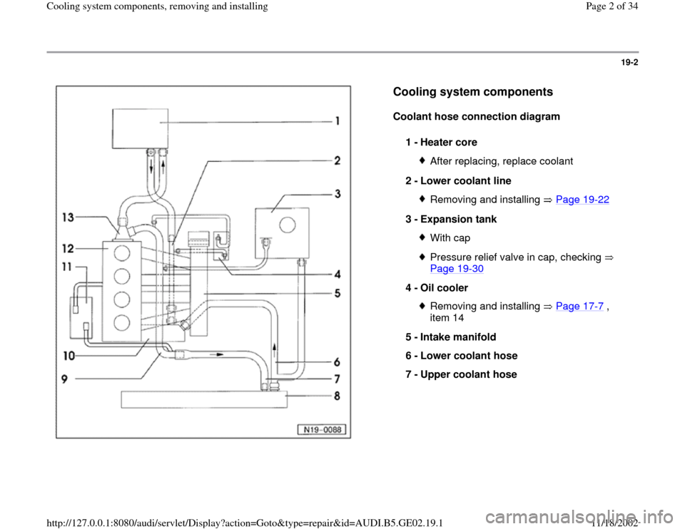
Cooling system components
Coolant hose connection diagram
1 -
Heater core
After replacing, replace coolant
2 -
Lower coolant line Removing and installing Page 19
-22
3 -
Expansion tank
With capPressure relief valve in cap, checking
Page 19
-30
4 -
Oil cooler
Removing and installing Page 17
-7 ,
item 14
5 -
Intake manifold
6 -
Lower coolant hose
7 -
Upper coolant hose
Pa
ge 2 of 34 Coolin
g system com
ponents, removin
g and installin
g
11/18/2002 htt
p://127.0.0.1:8080/audi/servlet/Dis
play?action=Goto&t
yp
e=re
pair&id=AUDI.B5.GE02.19.1
Page 7 of 34

19-7
Note (continued from page Page 19
-6 ):
G 011 A8 C or G 012 A8 D and coolant
additives marked with "according to TL VW
774C" or "according to TL VW 774 D", prevent
frost and corrosion damage as well as calcium
deposits. They also raise the boiling point.
Therefore, cooling system must be filled year-
round with frost and corrosion protection
additives.
A higher boiling point improves engine reliability
under heavy load, particularly in countries with
tropical climates.
Frost protection additives must protect against
frost to about -25 C (-13 F) and to about -35
C (-31 F) in arctic climates.
The coolant concentration must not be reduced
by adding water even in warmer seasons and in
warmer countries. The anti-freeze ratio must be
at least 40%.
If for climatic reasons greater frost protection is
required, the amount of G 011 A8 C or G 012
A8 D can be increased, but only up to 60% to
obtain frost protection to about -40 C (-40 F).
Otherwise frost protection and cooling
effectiveness will be reduced.
Pa
ge 7 of 34 Coolin
g system com
ponents, removin
g and installin
g
11/18/2002 htt
p://127.0.0.1:8080/audi/servlet/Dis
play?action=Goto&t
yp
e=re
pair&id=AUDI.B5.GE02.19.1
Page 26 of 34

19-22
Coolant line (lower), removing and
installing
Removing
- Drain coolant Page 19
-4 .
- Remove intake air duct between intake manifold
and charge air cooler.
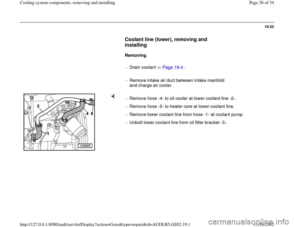
- Remove hose -4- to oil cooler at lower coolant line -2-.
- Remove hose -5- to heater core at lower coolant line.
- Remove lower coolant line from hose -1- at coolant pump.
- Unbolt lower coolant line from oil filter bracket -3-.
Pa
ge 26 of 34 Coolin
g system com
ponents, removin
g and installin
g
11/18/2002 htt
p://127.0.0.1:8080/audi/servlet/Dis
play?action=Goto&t
yp
e=re
pair&id=AUDI.B5.GE02.19.1
Page 28 of 34

19-24
Radiator, removing and installing
Special tools and equipment
VAG1306 drip tray
Removing
- Remove front bumper.
Repair Manual, Body Exterior, Repair Group
63
WARNING!
The cooling system is pressurized when the engine is warm. When
opening the expansion tank, wear gloves and other appropriate
protection, cover the cap using a cloth, and open carefully to relieve
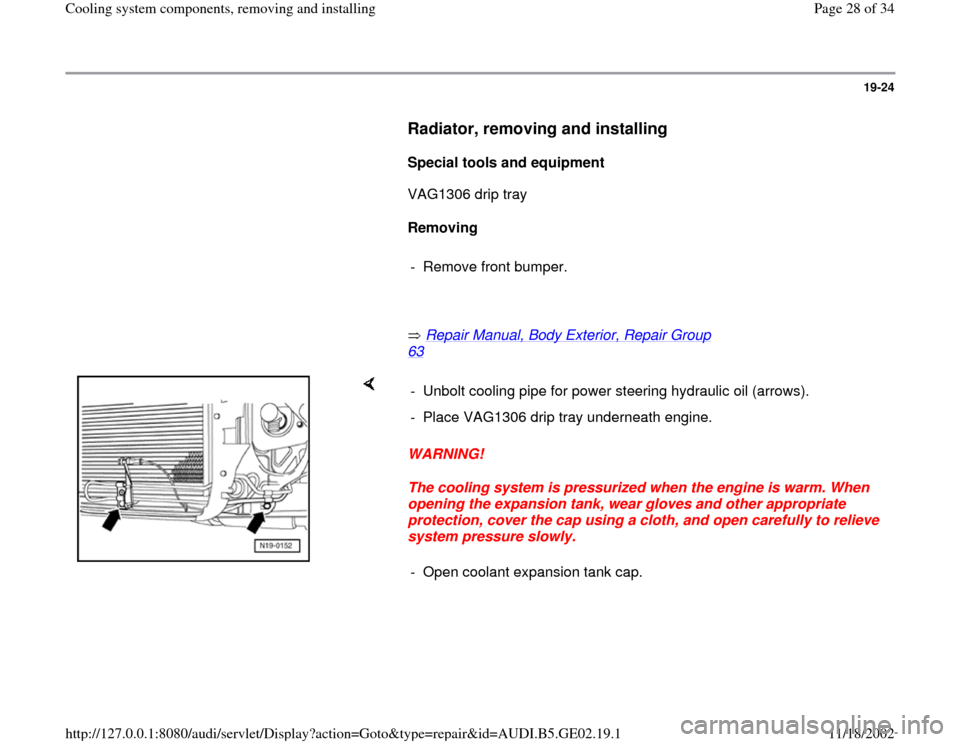
system pressure slowly. - Unbolt cooling pipe for power steering hydraulic oil (arrows).
- Place VAG1306 drip tray underneath engine.
- Open coolant expansion tank cap.
Pa
ge 28 of 34 Coolin
g system com
ponents, removin
g and installin
g
11/18/2002 htt
p://127.0.0.1:8080/audi/servlet/Dis
play?action=Goto&t
yp
e=re
pair&id=AUDI.B5.GE02.19.1