pump AUDI A3 2000 8L / 1.G AEB ATW Engines Cooling System Components Workshop Manual
[x] Cancel search | Manufacturer: AUDI, Model Year: 2000, Model line: A3, Model: AUDI A3 2000 8L / 1.GPages: 34, PDF Size: 0.54 MB
Page 3 of 34
19-3
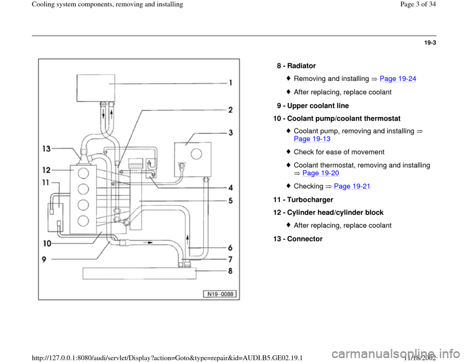
8 -
Radiator
Removing and installing Page 19
-24
After replacing, replace coolant
9 -
Upper coolant line
10 -
Coolant pump/coolant thermostat Coolant pump, removing and installing
Page 19
-13
Check for ease of movementCoolant thermostat, removing and installing
Page 19
-20
Checking Page 19
-21
11 -
Turbocharger
12 -
Cylinder head/cylinder block
After replacing, replace coolant
13 -
Connector
Pa
ge 3 of 34 Coolin
g system com
ponents, removin
g and installin
g
11/18/2002 htt
p://127.0.0.1:8080/audi/servlet/Dis
play?action=Goto&t
yp
e=re
pair&id=AUDI.B5.GE02.19.1
Page 6 of 34
19-6
Filling
Note:
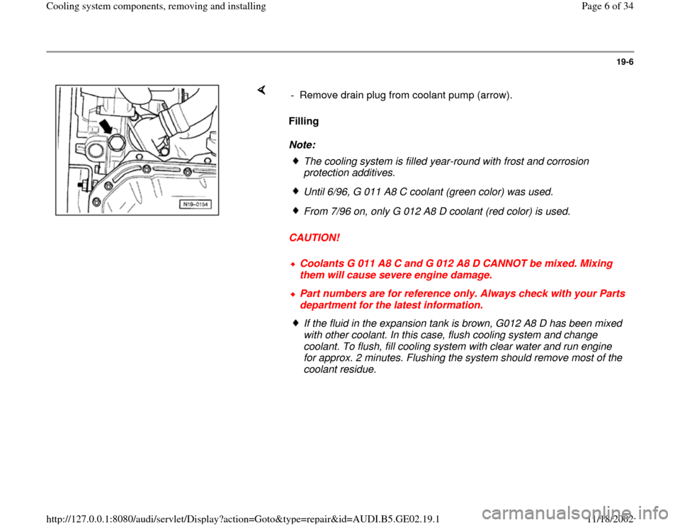
CAUTION! - Remove drain plug from coolant pump (arrow).
The cooling system is filled year-round with frost and corrosion
protection additives. Until 6/96, G 011 A8 C coolant (green color) was used.From 7/96 on, only G 012 A8 D coolant (red color) is used.Coolants G 011 A8 C and G 012 A8 D CANNOT be mixed. Mixing
them will cause severe engine damage. Part numbers are for reference only. Always check with your Parts
department for the latest information. If the fluid in the expansion tank is brown, G012 A8 D has been mixed
with other coolant. In this case, flush cooling system and change
coolant. To flush, fill cooling system with clear water and run engine
for approx. 2 minutes. Flushing the system should remove most of the
coolant residue.
Pa
ge 6 of 34 Coolin
g system com
ponents, removin
g and installin
g
11/18/2002 htt
p://127.0.0.1:8080/audi/servlet/Dis
play?action=Goto&t
yp
e=re
pair&id=AUDI.B5.GE02.19.1
Page 9 of 34
19-8
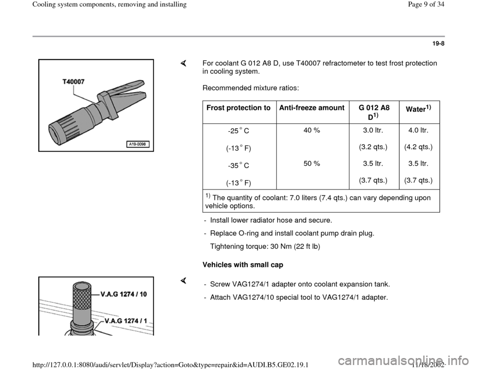
For coolant G 012 A8 D, use T40007 refractometer to test frost protection
in cooling system.
Recommended mixture ratios:
Vehicles with small cap Frost protection to
Anti-freeze amount
G 012 A8
D
1) Water
1)
-25 C
(-13 F)
-35 C
(-13 F)
40 %
50 % 3.0 ltr.
(3.2 qts.)
3.5 ltr.
(3.7 qts.) 4.0 ltr.
(4.2 qts.)
3.5 ltr.
(3.7 qts.)
1) The quantity of coolant: 7.0 liters (7.4 qts.) can vary depending upon
vehicle options.
- Install lower radiator hose and secure.
- Replace O-ring and install coolant pump drain plug.
Tightening torque: 30 Nm (22 ft lb)
- Screw VAG1274/1 adapter onto coolant expansion tank.
- Attach VAG1274/10 special tool to VAG1274/1 adapter.
Pa
ge 9 of 34 Coolin
g system com
ponents, removin
g and installin
g
11/18/2002 htt
p://127.0.0.1:8080/audi/servlet/Dis
play?action=Goto&t
yp
e=re
pair&id=AUDI.B5.GE02.19.1
Page 12 of 34
19-11
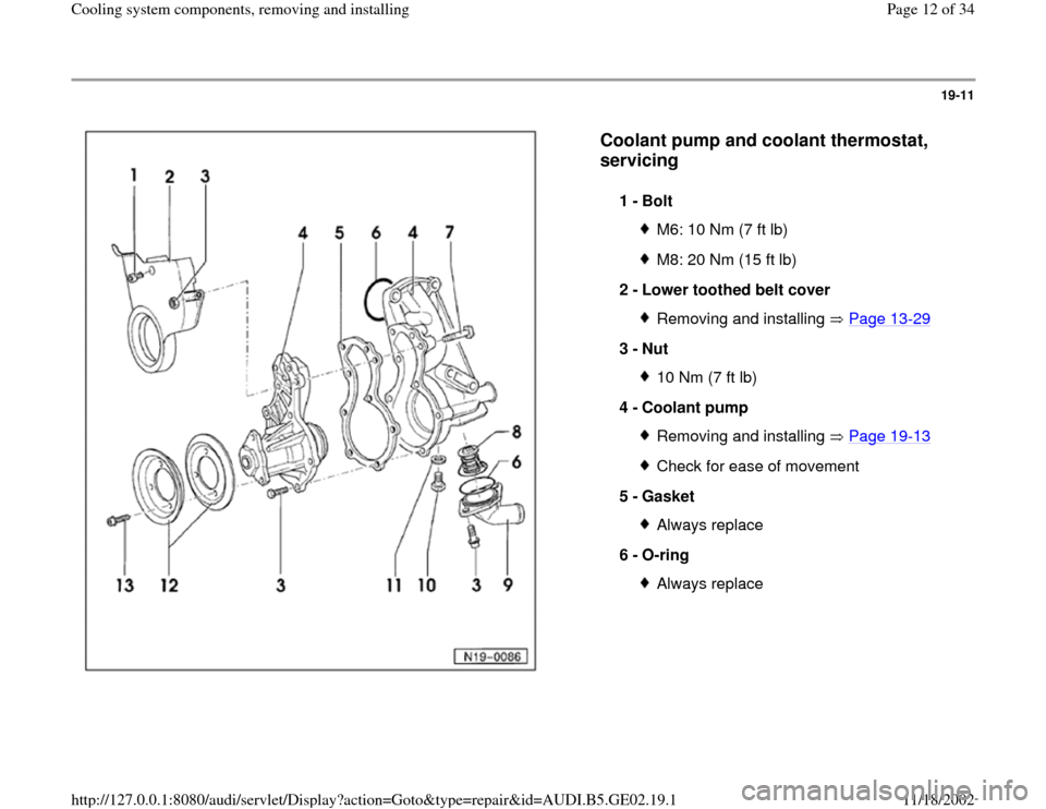
Coolant pump and coolant thermostat,
servicing
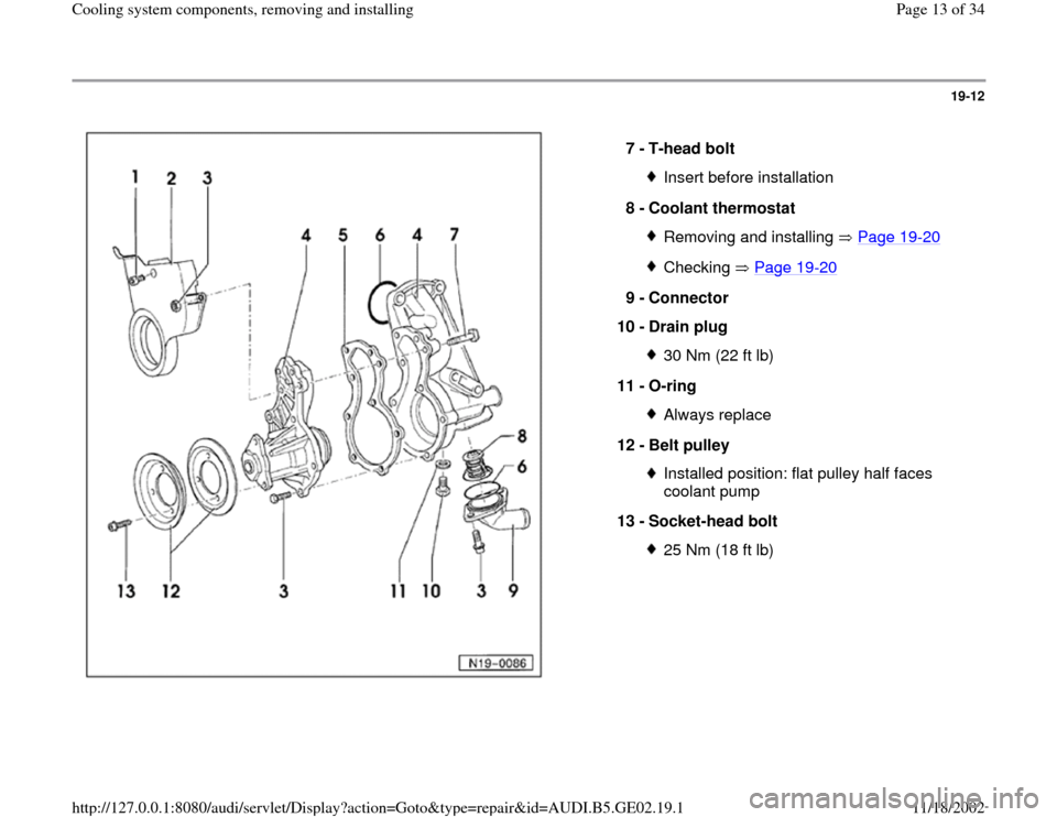
1 -
Bolt
M6: 10 Nm (7 ft lb)M8: 20 Nm (15 ft lb)
2 -
Lower toothed belt cover Removing and installing Page 13
-29
3 -
Nut
10 Nm (7 ft lb)
4 -
Coolant pump Removing and installing Page 19
-13
Check for ease of movement
5 -
Gasket Always replace
6 -
O-ring Always replace
Pa
ge 12 of 34 Coolin
g system com
ponents, removin
g and installin
g
11/18/2002 htt
p://127.0.0.1:8080/audi/servlet/Dis
play?action=Goto&t
yp
e=re
pair&id=AUDI.B5.GE02.19.1
Page 13 of 34
19-12
7 -
T-head bolt
Insert before installation
8 -
Coolant thermostat Removing and installing Page 19
-20
Checking Page 19
-20
9 -
Connector
10 -
Drain plug
30 Nm (22 ft lb)
11 -
O-ring Always replace
12 -
Belt pulley Installed position: flat pulley half faces
coolant pump
13 -
Socket-head bolt 25 Nm (18 ft lb)
Pa
ge 13 of 34 Coolin
g system com
ponents, removin
g and installin
g
11/18/2002 htt
p://127.0.0.1:8080/audi/servlet/Dis
play?action=Goto&t
yp
e=re
pair&id=AUDI.B5.GE02.19.1
Page 14 of 34
19-13
Coolant pump, removing and installing
Note:
Coolant pump is bolted to bracket for generator,
power steering pump and viscous fan.
Lock carrier in service position Page 13
-1
Removing
CAUTION!
Before disconnecting the battery:
Stop the engine.
Determine the correct coding for the anti-
theft radio.
Switch the ignition off (also applies when
connecting the battery). Failure to do so may
damage the Engine Control Module (ECM).
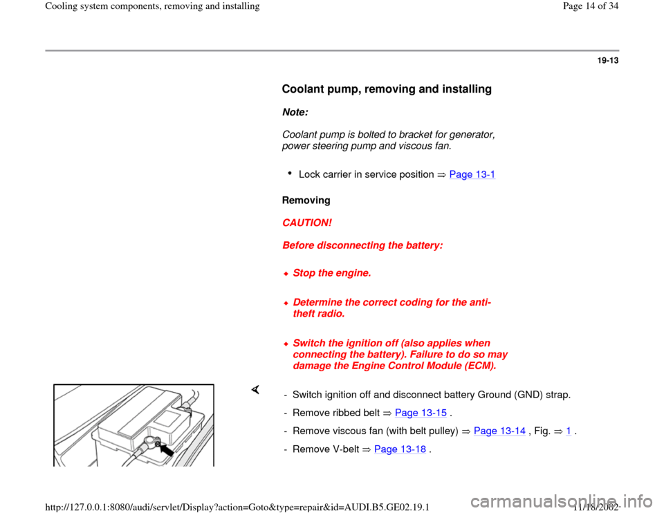
- Switch ignition off and disconnect battery Ground (GND) strap.
- Remove ribbed belt Page 13
-15
.
- Remove viscous fan (with belt pulley) Page 13
-14
, Fig. 1
.
- Remove V-belt Page 13
-18
.
Pa
ge 14 of 34 Coolin
g system com
ponents, removin
g and installin
g
11/18/2002 htt
p://127.0.0.1:8080/audi/servlet/Dis
play?action=Goto&t
yp
e=re
pair&id=AUDI.B5.GE02.19.1
Page 16 of 34
19-14
- Drain coolant Page 19
-4 .
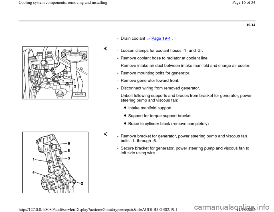
- Loosen clamps for coolant hoses -1- and -2-.
- Remove coolant hose to radiator at coolant line.
- Remove intake air duct between intake manifold and charge air cooler.
- Remove mounting bolts for generator.
- Remove generator toward front.
- Disconnect wiring from removed generator.
- Unbolt following supports and braces from bracket for generator, power
steering pump and viscous fan:
Intake manifold support
Support for torque support bracket
Brace to cylinder block (remove completely)
- Remove bracket for generator, power steering pump and viscous fan
bolts -1- through -6-.
- Secure bracket for generator, power steering pump and viscous fan to
left side using wire.
Pa
ge 16 of 34 Coolin
g system com
ponents, removin
g and installin
g
11/18/2002 htt
p://127.0.0.1:8080/audi/servlet/Dis
play?action=Goto&t
yp
e=re
pair&id=AUDI.B5.GE02.19.1
Page 17 of 34
19-15
Note:
Power steering pump remains installed.
- Pull off coolant hoses from coolant pump and
coolant thermostat housing.
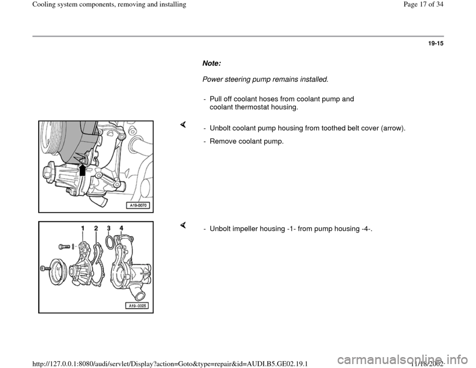
- Unbolt coolant pump housing from toothed belt cover (arrow).
- Remove coolant pump.
- Unbolt impeller housing -1- from pump housing -4-.
Pa
ge 17 of 34 Coolin
g system com
ponents, removin
g and installin
g
11/18/2002 htt
p://127.0.0.1:8080/audi/servlet/Dis
play?action=Goto&t
yp
e=re
pair&id=AUDI.B5.GE02.19.1
Page 18 of 34
19-16
Installing
Installation is the reverse of removal, noting the
following:
- Clean sealing surfaces of both housings.
- Replace gasket and O-ring.
- Insert T-head bolt into coolant pump bore.
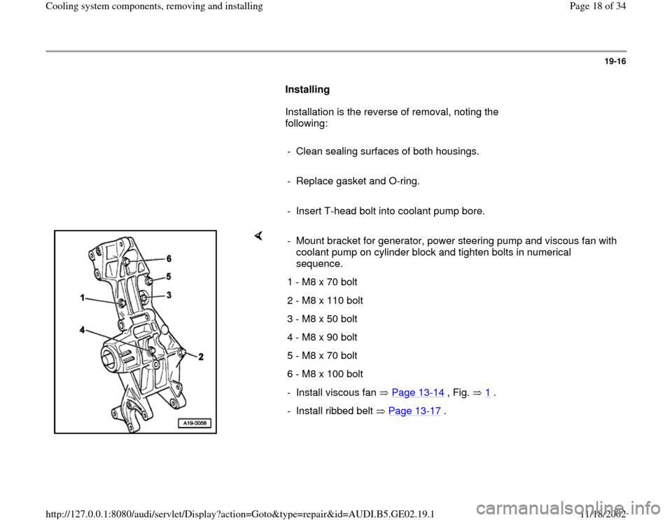
- Mount bracket for generator, power steering pump and viscous fan with
coolant pump on cylinder block and tighten bolts in numerical
sequence.
1 - M8 x 70 bolt
2 - M8 x 110 bolt
3 - M8 x 50 bolt
4 - M8 x 90 bolt
5 - M8 x 70 bolt
6 - M8 x 100 bolt
- Install viscous fan Page 13
-14
, Fig. 1
.
- Install ribbed belt Page 13
-17
.
Pa
ge 18 of 34 Coolin
g system com
ponents, removin
g and installin
g
11/18/2002 htt
p://127.0.0.1:8080/audi/servlet/Dis
play?action=Goto&t
yp
e=re
pair&id=AUDI.B5.GE02.19.1
Page 21 of 34
19-18
Tightening torques
Component
Tightening
torques
Impeller to pump housing 10 Nm (7 ft
lb)
Pump housing to toothed belt
cover 10 Nm (7 ft
lb)
Bracket for generator, power
steering pump and viscous fan to
cylinder block 25 Nm (18 ft
lb)
Left brace for cylinder
block/bracket for generator, power
steering pump and viscous fan
to cylinder block 25 Nm (18 ft
lb)
to bracket M10 40 Nm (30 ft
lb)
Brace for torque support/bracket
for generator, power steering
pump and viscous fan
to torque support 25 Nm (18 ft
lb)
to bracket 20 Nm (15 ft
lb)
Intake duct support
Pa
ge 21 of 34 Coolin
g system com
ponents, removin
g and installin
g
11/18/2002 htt
p://127.0.0.1:8080/audi/servlet/Dis
play?action=Goto&t
yp
e=re
pair&id=AUDI.B5.GE02.19.1