ignition AUDI A3 2011 Owner´s Manual
[x] Cancel search | Manufacturer: AUDI, Model Year: 2011, Model line: A3, Model: AUDI A3 2011Pages: 320, PDF Size: 75.79 MB
Page 241 of 320

___________________________________________ C_ h_e _c _k_ i_n ~g_ a_n_ d_ f_ i_ll _i_n _g __ _
nected. These functions have to be relearned after the battery termi
nals are connected again. To prevent this, the battery should only be
disconnected from the vehicle electrical system if absolutely neces
sary.
Power window one-touch
up/down function
Reprogramming
~ page 51, "Reactivating the sys
tem after battery disconnection"
Master key with remote control Synchronization~
page 43
Digital clock ~ page 9
ESP indicator light The indicator light goes out after
driving a few meters
Vehicles not driven for long periods and short
distance operation
If you do not drive your vehicle for several days or weeks, e lectrical
consumers are gradually scaled back or switched off. Th is reduces
energy use and ensures the vehicle will be able to start after long
periods of time~
page 194. Some convenience functions such as
opening with the remote control key may not be available. These
convenience functions will be available again once you switch the
ignition on and start the engine. Even when consumers are switched
off, the battery will become deeply discharged by stand-by power
consumers if the vehicle is not driven for several months . Deep
discharging results in a chemica l reaction that destroys the inside of
the battery. The battery must be charged every month to prevent th is
~ page 241. Do not disconnect the battery or the anti-theft alarm
system* will not work.
Winter operation
Cold weather places higher demands on the battery. This results in
reduced starting abi lity. Have the battery checked and recharged if
necessary before the cold weather beg ins.
Avoid unnecessary power consumption, part icularly in city traffic or
when travel ing on ly short distances. Let your author ized Audi dealer
Safety first
check the capacity of the vehicle battery before winter sets in
~ page 241. A well charged battery will not only p revent start ing
problems when the weather is cold, but will also last longer.
(D Note
• All work on the battery requires techn ical knowledge. Please
contact an Audi dealership or another authorized facility for ques
tions about the battery- danger of acid burns and explosion hazard!
• The battery m ust not be opened! Do not try to change the
battery's liquid level, otherwise detonating gas will escape from the
battery - explosion hazard!
• The AGM battery in the luggage compartment cannot leak,
because the electrolyte for this battery is absorbed into a specia l
glass mat . This leak -proof battery must not be replace with a conven
tional battery .
• Make sure the ventilation hose on the side of the battery is
connected, otherwise fumes or battery acid can leak out.
• Battery holder and terminals always have to be secured correctly .
• Before all work on the battery follow the
warnings below~ & in
"Working on the battery" on
page 239. •
Working on the battery
All work on the battery requires technical knowledge! Be
especially careful when working on or near the battery!
Before you check anything in the engine compartment,
always
read and heed all WARNINGS~ & in "Working in
the engine compartment" on
page 226 .
Always heed the safety warnings, when working on the vehicle
battery or the vehicle electrical system to prevent injury .
Vehicle care Technical data
Page 242 of 320
-L~C::!h~e~c~k:.!_i~n~g~a~n~d~f~il~l:!_!in~g !...._ ________________________________________ _
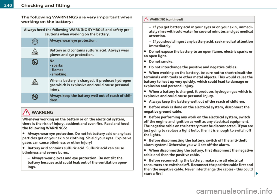
The following WARNINGS are very important when
working on the battery:
Always heed the following WARNING SYMBOLS and safety pre cautions when working on the battery .
@
®
Always wear eye protection.
Battery acid contains sulfuric acid. Always wear
gloves and eye protection.
No
• s parks
- flames
• smoking .
When a battery is charged, it produces hydrogen
gas which is explosive and could cause persona l
injury.
Always keep the battery well out of reach of chil
dren .
& WARNING
Whenever working on the battery or on the electrical system,
there is the risk of injury , accident and even fire. Read and heed
the following WARNINGS:
• Always wear eye protection . Do not let battery acid or any lead
particles get on your skin or clothing. Shield your eyes . Explosive
gases can cause blindness or other injury!
• Battery acid contains sulfuric acid. Sulfuric acid can cause blindness and severe burns.
-Always wear gloves and eye protection. Do not tilt the
battery because acid could leak out of the ventilation open
ings.
& WARNING (co ntinued )
-If you get battery acid in your eyes or on your skin, immedi
ately rinse with cold water for several minutes and get medical
attention.
- If you should ingest any battery acid, seek medical attention
immediately.
• Do not expose the battery to an open flame, electric sparks or
an open light .
• Do not smoke.
• Do not interchange the positive and negative cables.
• When working on the battery , be sure not to short-circuit the
terminals with tools or other metal objects. This would cause the battery to heat up very quickly, which could lead to damage or
explosion and personal injury.
• When a battery is charged , it produces hydrogen gas which is
explosive and could cause personal injury.
• Always keep the battery well out of the reach of children.
• Before work is done on the electrical system, disconnect the
negative ground cable.
• Before performing any work on the electrical system, switch
off the engine and ignition as well as any electrical equipment.
The negative cable on the battery must be disconnected . If you are
just going to replace a light bulb, then it is enough to switch off the lights.
• Before disconnecting the battery, switch off the anti-theft
alarm system! Otherwise you will set off the alarm .
• When disconnecting the battery, first disconnect the negative
cable and then the positive cable .
• Before reconnecting the battery, make sure all electrical
consumers are switched off . Reconnect the positive cable first and
then the negative cable. Never interchange the cables· this could start a fire! ..,_
Page 243 of 320
_____________________________________________ C_h _ e_ c_ k_in --= g'-- a_n _d_ f_i _ll _i_n -=g ::;__ ____.fflll
& WARNING (continued)
• Never charge a frozen or a thawed-out battery. It could
explode! If a battery has frozen, then it must be replaced. A
discharged battery can freeze over at 32 °F (0 °C).
• Make sure the vent hose is always attached to the opening on
the side of the battery.
• Never use batteries which are damaged. There is the danger of
an explosion! Always replace a damaged battery.
& WARNING
California Proposition 65 Warning:
• Battery posts, terminals and related accessories contain lead
and lead compounds, chemicals known to the State of California
to cause cancer and reproductive problems. Wash hands after
handling.
0 Note
• Do not disconnect the vehicle battery when the ignition is
switched on or when the engine is running, otherwise, you will
damage electronic components in the electrical system.
• When working on the engine, protect the battery housing from
ultraviolet (UV) rays by not parking the vehicle in direct sunlight .
• If your vehicle is going to stand for a long period of time without
being driven, protect the battery from "freezing", otherwise it will be
damaged and will then have to be replaced::::;,
page 241. •
Vehicle OP-eration
Charging of battery
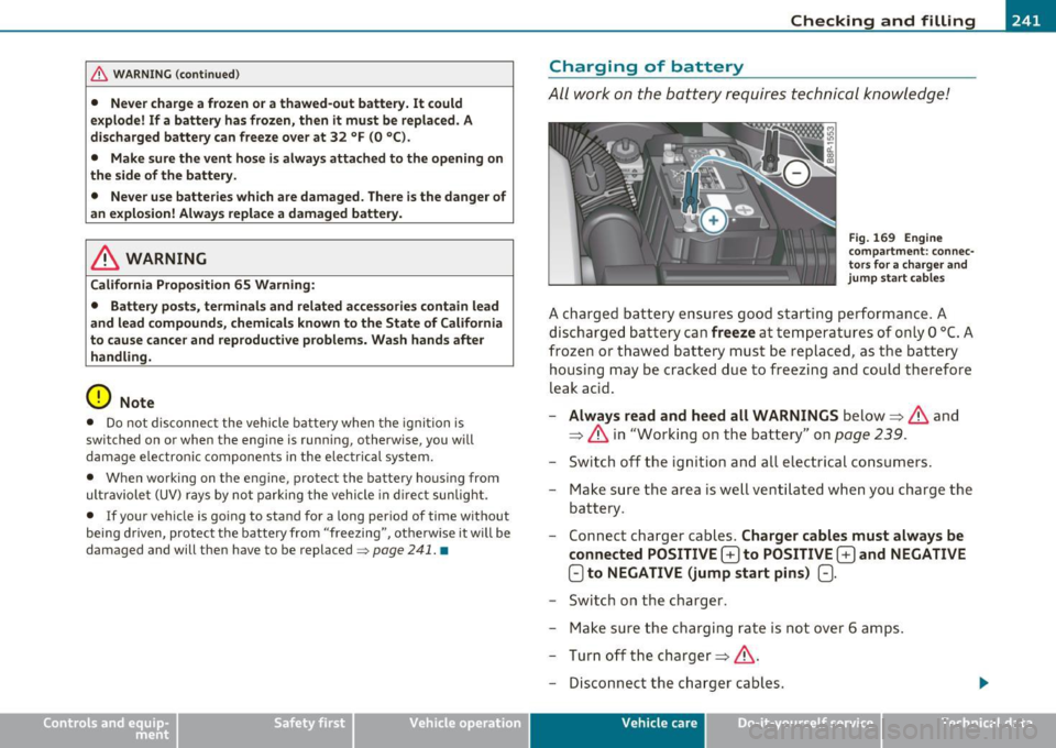
All work on the battery requires technical knowledge!
Fig. 169 Engine
compartment: connec
tors for a charger and
jump start cables
A charged battery ensures good starting performance. A
discharged battery can
freeze at temperatures of only O °C. A
frozen or thawed battery must be replaced, as the battery
housing may be cracked due to freezing and could therefore
leak acid.
- Always read and heed all WARNINGS below==> & and
==> & in "Working on the battery" on
page 239.
-Switch off the ignition and all electrical consumers.
- Make sure the area is well ventilated when you charge the
battery .
- Connect charger cables .
Charger cables must always be
connected POSITIVE
G to POSITIVE G and NEGATIVE
Oto NEGATIVE (jump start pins) (:).
-Switch on the charger.
- Make sure the charging rate is not over 6 amps.
- Turn off the charger==> &.
- Disconnect the charger cables.
Vehicle care Do-it-yourselt service iTechnical data
Page 245 of 320
___________________________________________ C_ h _ e_c _k _ i_n -=g .._ a_n _ d_ f_i _ll _i _ n -=g '-- ....... fflll
=:> page 194. The intelligent energy management system will keep
the eng ine battery charged bette r then vehicles withou t this system .
To make sure the additional electrical energy is available o nce again
after you have changed the battery, we recommend t hat you install
batteries of the same type and manufacture only (the same as those
installed at the time your vehicle was delivered). Specif ications are
listed on the batte ry ho using. Your authorized dealer must code the
battery in the energy management system to enable you to use the
ene rgy management functions correct ly after replacing the battery.
If it is not poss ible to use a battery of this type, the new battery must
have the same capacity, voltage (12 volts), amperage, construct ion
and plug sealing.
We recommend that you use maintenance-free or
c y cle-re sis
tant /le ak -proof
batteries that conform to the standards TL 82S 06
(from December 1997) and
VW 7 50 73 (from August 2001).
When installing the battery, make sure the ignition and all electrical
consumers are turned off.
0 Note
• Make s ure that the gas venting hose is always connected to the
original opening on the battery side . Otherwise gasses or battery acid
co uld leak out.
• Battery mounts and clamps must a lways be secured correctly.
• Read and follow the warn ings under=:>
page 239, "Work ing on
the batte ry" before performing any work on the battery .
c£> For the sake of the environment
Because of the problem of proper disposal of a battery, we recom
mend your authorized Audi dealer change the battery for you.
Batteries contain sulfuric acid and lead and must always be d isposed
of prope rly in compliance with all env ironmenta l regulatio ns.
Disposing of vehicle batteries improperly is very dangerous to the
environment . M ake sure that the removed battery cannot overbal
ance, otherw ise sulfur ic acid might escape! •
Vehicle OP-eration
Windshield washer container
Using plain water is not adequate for filling the wind
shield washer system.
Fig . 1 70 En gine
co mpa rt ment : win d
s hi eld w as her f luid
con taine r
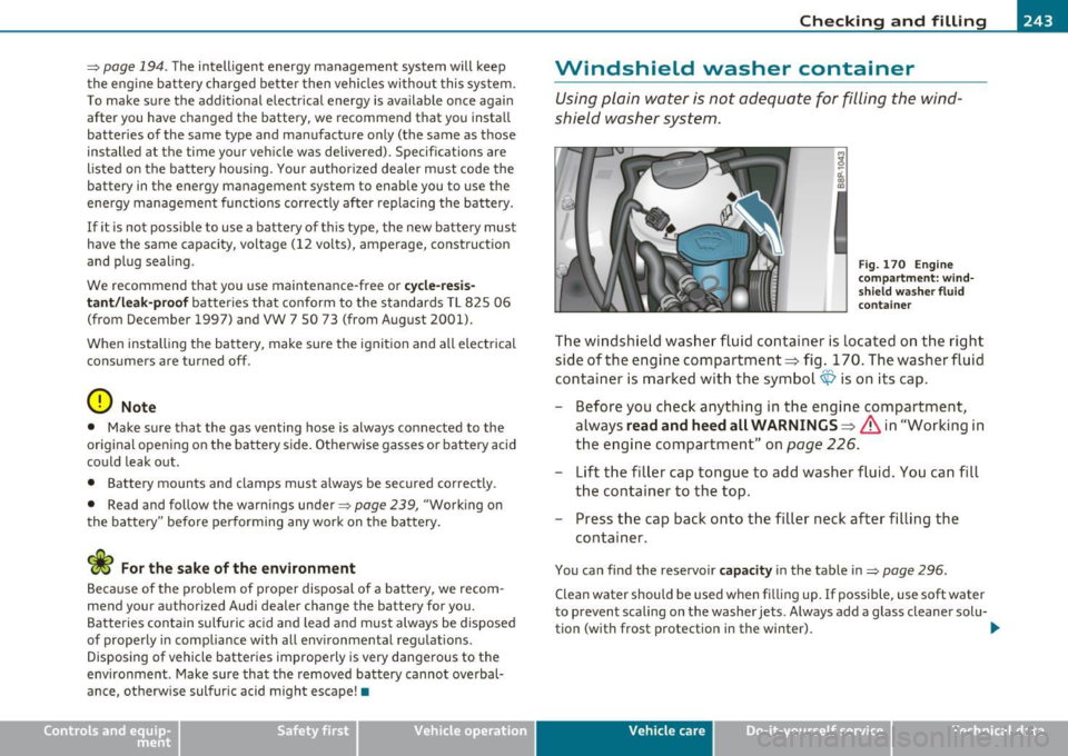
The windshield wash er fluid container is loca ted on the right
side of the engine compartment:::::;, fig. 170 . The washer flui d
co nta iner is mar ked with the symbol~ is on its cap.
- Before you ch eck anythin g in t he e ngine compartment,
always
read and heed all WARNINGS=> & in "Working in
the e ng ine compartment" on
page 226.
- Lift t he fi ller cap tongue to add washer fluid. You can fill
th e container to the top.
- Press the cap back onto the filler neck after filling the
container.
You can find the reservoir capacity in the table in=> page 296.
Clean water should be used when fi lling up. If possible, use soft water
to prevent scaling on the washer jets . Always add a glass cleaner solu-
tion (with frost protection in the winter).
tJ,,,
Vehicle care Do-it-yourselt service iTechnical data
Page 268 of 320
-~_T_ ir_e_ s_ a_ n_ d_ w_ h_e_ e_ ls _______________________________________________ _
The ti re pr essure mon itor ing must be reset in the m enu display each
t im e th e pre ssur es a re adjust ed (e .g . w hen sw itching b etwee n parti al
and full load press ure) o r afte r ch angi ng or r eplac ing a tir e on yo ur
vehicle => page
26 7. You ca n find t he recommen ded tire pr essures
for your veh icle o n th e labe l o n the dr ive r's door pillar=> page
249 .
Tire tread circ umference and vibrat ion characterist ics ca n change and
c a us e a tir e pre ssure w arni ng if:
• t he tire pressure in one o r more tires is to o low,
• t he tire has st ru ctu ral damag e,
• the ti re press ure was changed , wh eels ro tate d or r ep laced but the
TPM S was not re set=> page
267 .
Warning symbols
1..1' Loss of p ress ure in at least on e tir e => & . Check th e tir e or tir es
and rep lace or re pair i f necessary. T he in dicator lig ht (• in th e ins tru
men t cluster al so illu mina tes=> page
11. Che ck/co rrect the pre s
sures of a ll four tires an d reset TP MS in t he menu display.
rr :; (T ire Pre ss ure M on itor ing Syst em) Tire pressure! System
malfunction.
I f T ,.;> ap pears a fter swi tc hi ng t he ignition o n or w hile
dr iv ing => page
265 , fig. 177 a nd t he in dic ator lig ht 'in th e i nstr u
m en t clus ter bli nks fo r ap prox ima tely one minute and th en stays o n,
t h ere is a system ma lf u nct io n. S ee your authorized Audi dealer as
soon as poss ible.
& WARNING
• If the tire pressure indicator appears in the instrument cluster
display, one or more of your tires is significantly under-inflated. Reduce your speed immediately and avoid any hard steering or
braking maneuvers. Stop as soon as possible and check the tires
and their pressures . Inflate the tire pressure to the proper pres
sure as indicated on the vehicle's tire pressure label=>
page 249.
Driving on a significantly under-inflated tire causes the tire to
overheat and can lead to tire failure. Under-inflation also is likely
to impair the vehicle's handling and stopping ability.
& WARNING (co ntinued )
• The driver is responsible for maintaining the correct tire pres
sures . You must check the tire pressures regularly .
• Under certain conditions (such as a sporty driving style, winter
conditions or unpaved roads), the pressure monitor indicator may
be delayed.
• Ask your authorized Audi dealer if run-flat tires may be used on
your vehicle. Your vehicle registration becomes invalid if you use
these tires when not permitted. Damage to your vehicle or acci dents could also result.
[ i ] Tips
• Th e tire pressu re monito ring system stops wor king when the re is
a n E SP/ABS malfu nct io n.
• U sin g s now c hains may res ult in a system ma lf u n ct io n.
• Tire s with t he ident ification "AO" or "RO" have been specially
m atched w ith yo ur Audi. We recommend usin g onl y these t ires
b ecause they mee t the hig hest standards regard ing safe ty a nd
dr iving charac ter is ti cs when used cor rec tly . Yo ur au thori ze d Audi
dea ler will g lad ly provi de you wi th mor e info rmation. •
Page 270 of 320
![AUDI A3 2011 Owner´s Manual ffl __ T_ i_ r _e _s_ a_n_ d_ w_ h_ e_e_ l_ s _______________________________________________ _
Fig . 181 Display : T ir e
p res su re
[ Rese t] button @ and rocker switch @=> page 267,
fig. AUDI A3 2011 Owner´s Manual ffl __ T_ i_ r _e _s_ a_n_ d_ w_ h_ e_e_ l_ s _______________________________________________ _
Fig . 181 Display : T ir e
p res su re
[ Rese t] button @ and rocker switch @=> page 267,
fig.](/img/6/40268/w960_40268-269.png)
ffl __ T_ i_ r _e _s_ a_n_ d_ w_ h_ e_e_ l_ s _______________________________________________ _
Fig . 181 Display : T ir e
p res su re
[ Rese t] button @ and rocker switch @=> page 267,
fig. 178 functions:
Storing tire pressures
- Turn on the ignition.
- Select the menu:
>Adjusting *> Tire pressure > Store .
Entering and confirming
- Sele ct t he menu : Store now
- Press the [
Reset] button@.
- Select the menu: Confirm
- Press the [
Reset I button @.
Returning to the Start menu
- Press the [Reset] button longer than 2 seconds to re turn
from a ny menu level to the Start menu .
(I) Tips
Before resetti ng the TPM S, the cur rent pressures of all four tires
must correspond to the specified values . Adjust the tire pressure and reset the pressure i
n the t ire pressure mon itoring system accord ing
t o the loa d you are ca rrying =>
page 249. •
Page 283 of 320
______________________________________________ F _u_s _e_ s_ a_ n_ d _ b _u_l_b _ s _ ___.fflll
Fuses and bulbs
Electrical fuses
Replacing fuses
A problem in the electrical system may be caused by a
blown fuse .
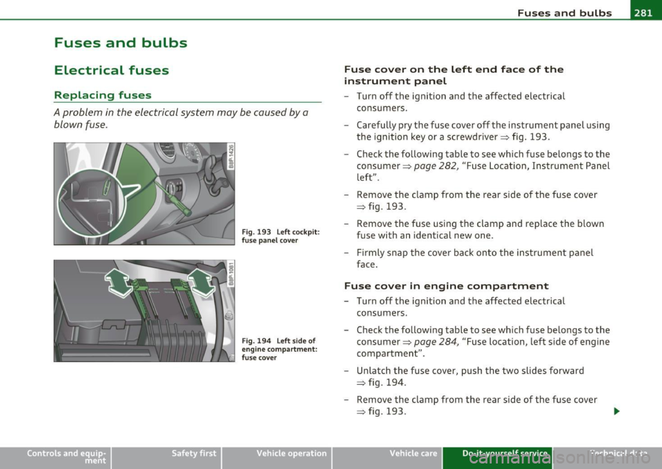
Fig. 193 Left cockpit:
f use pa nel cover
Fig. 19 4 Left s ide o f
engine compar tm ent:
' fuse cove r
Vehicle OP-eration
Fuse cov er on th e left end fac e of th e
instrum ent pan el
- Turn off the ignition and the affected electrical
consumers .
- Carefully pry the fuse cover off the instrument panel using the ignition key or a screwdriver=> fig. 193 .
- Check the following table to see which fuse belongs to the
consumer =>
page 282, "Fuse Location, Instrument Panel
left".
- Remove the clamp from the rear side of the fuse cover
=> fig. 193 .
- Remove the fuse using the clamp and replace the blown fuse with an identical new one .
- Firmly snap the cover back onto the instrument panel
face .
Fuse cover in engine compa rtment
- Turn off the ignition and the affected electrical
consumers.
- Check the following table to see which fuse belongs to the
consumer =>
page 284, "Fuse location, left side of engine
compartment" .
- Unlatch the fuse cover, push the two slides forward => fig. 194.
- Remove the clamp from the rear side of the fuse cover
=> fig. 193.
Vehicle care Do-it-yourself service iTechnical data
Page 286 of 320
lffll.,___F_ u_ s_e _ s_ a_n_d _b_u _ l_ b_s _______________________________________________ _
(I) Tips
• Whenever replacing a fuse, always consult the sticker on the
i ns ide of the fuse panel cover. It contains the most up-to-date infor
mation regarding the fuse arrangement . If in doubt , ask your autho
rized Audi Service advisor.
• Some of the equipment items listed are optiona l or only available
on certain model configurations. •
Fuse location, left side of engine
compartment
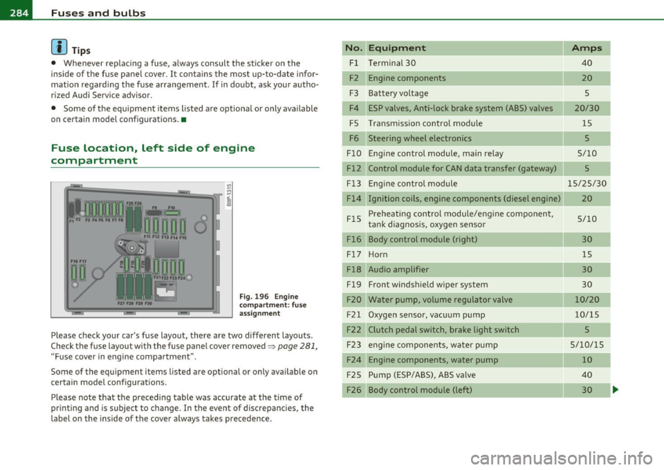
Fig. 196 Engine
compart ment: fuse
assignment
Please check your car's fuse layout, there are two different layouts.
Check the fuse layout with the fuse panel cover removed~
page 281,
"Fuse cover in engine compartment ".
Some of the equipment items listed are optional or only available on
certain model configurations .
Please note that the preceding table was accurate at the time of
printing and is subject to change . In the event of discrepancies, the
label on the inside of the cover always takes precedence .
No. Equipment
Fl Terminal 30
F2 Engine components
F3 Batteryvoltage
F4 ESP valves, Anti-lock brake system (ABS) valves
FS Transmission control module
F6 Steering wheel electronics
FlO Engine control module, main relay
Fl2 Control module for CAN data transfer (gateway)
Fl3
FlS
Fl6 Engine
control module
Ignition coils, engine components (diesel engine)
Preheating control module/engine component,
tank diagnosis, oxygen sensor
Body control module (right)
F l7 Ho rn
Fl8 Audio amplifier
Fl9 Front
windshield wiper system
F20 Water pump, volume regulator valve
F21 Oxygen sensor, vacuum pump
F22 Clutch pedal switch, brake light switch F23 engine components, water pump
F24 Engine components, water pump
F25 Pump (ESP/ABS), ABS va
lve
F26 Body control module (left)
Amps
40
20
s
20/30 15
5
5/10
5
15/25/30
20
5/10 30 15
30
30
10/20
10/15
5
5/10/15 10
40 30
Page 289 of 320
_____________________________________________ E_ m_ e_r-= g ::.. e_ n_c-= y'- s_ i_t _u _a_ t_ i_ o _ n_ s __ fflll
& WARNING (co ntinued )
• Before you che ck anything in the engine compartment , alway s
r e ad and heed all WARNINGS =>
page 218, "Engi ne compart
ment ".
0 Note
• App lying a higher vo ltage booster battery will cause expens ive
damage to sens itive e lec tro nic components, such as contro l units,
re lays, rad io, etc.
• Th ere must be no electrical contact between the veh icles as othe r
wise current could a lready sta rt to flow as soon as the posit ive(+)
term inals are con nected.
• Improperly connecte d jumper cables can cause substantial
damage to the e lectr ica l system of the vehicle .
[I) Tips
• The discharged batte ry mu st be properly co nne cted to the
vehicle's elect rical system. •
General information of starting
assistance
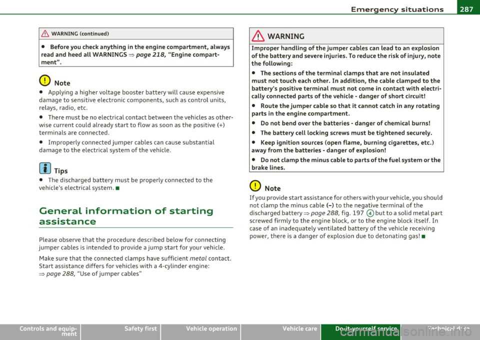
Please observe that the procedure descr ibed below for connect ing
jumpe r cab les is intended to p rovide a ju mp s tart for your ve hicl e.
Make sure t hat the co nnected clamps have suff ic ient
metal contact.
Sta rt assistance differs for vehicles w ith a 4-cylinde r engine:
=> page 288, "Use of jumper cables"
Safety first
& WARNING
Improper handling of the jumper cables can lead to an explosion
of the battery and severe injurie s. To reduce the ri sk of injury, note
the following:
• The section s of the terminal clamps that are not insul ated
must not touch each other. In addition, the cable clamped to the
battery' s po sitive terminal must not come in contact with electri
cally connected parts of the veh icle -danger of short circu it!
• Route the jumper cable so that it cannot catch in any rotating
parts in the engine compartment .
• Do not bend over the batteries -danger of chemical burns!
• The battery cell locking screws must be tightened securely.
• Keep ignition source s (open flame , burning cigarettes, etc.)
away from the batteries -danger of explosion!
• Do not clamp the minus cable to parts of the fuel system or the
brake lines.
0 Note
If you prov ide sta rt assistance for others with your vehi cle, you shou ld
not clamp the minus cable( -) to the negative te rm inal of the
discharged batte ry =>
page 288, fig. 19 7 © but to a solid metal part
sc rewed firm ly to the eng ine b lock, or to the e ng ine block itse lf . In
case of an inadequately venti lated battery o f the veh icle receiving
powe r, the re is a dange r of explosi on du e to detonat ing gas! •
Vehicle care Do-it-yourself service Technical data
Page 297 of 320

________________________________________________ G ..... e_ n_e ___ ra ___ l_i_n _ f_ o ___ r_m :....:....: a ..... t ..... i...: o ..... n---- --
left door jamb . It shows the month and year of production and the
vehicle iden tifica tion n umber of your veh icle ( perfo ration) as well as
the Gross Vehicle Weight Rating (GVWR) and the Gross Axle Weight Rating (GAWR).
The high voltage warning label
is loca ted on the loc k carr ier .
The spark ignition system complies with the
Canadian standard ICES-002. •
Weights
Gross Vehicle Weight Rating
The Gross Vehicle Weight Rating (GVWR), and the Gross Axle Weight
Ra ting (GAWR) for fron t and rear are listed on a st icker on the left
door jamb.
Th e Gross Vehicle Weight Rating includes the weight of the basic
vehicle plus f ull fue l tank, oil and coo la nt, plus max im um load, which
includes passenger we ight (150 lbs/68 kg per des ignated seating
position) a nd luggage weight .
Gross Axle Weight Rating
The Gross Axle Weight Rating is the maximum load that can be
applie d at each axle of the vehicle~& .
Vehicle capacity weight
The vehicle capacity weight (max. load) is liste d either o n the driver's
side B -pillar or inside the fuel f iller flap .
Roof weight
The maximum permiss ible roof weight is 165 lb (75 kg ). The roof
we igh t is ma de up o f the weig ht of the roof rack sys tem and the
we ight of the object being transported~
page 88, "Load ing the roof
rack" .
Safety first
& WARNING
• The actual Gross Axle Weight Rating at the front and rear axles
s hould not exceed the permis sible weights, and their combination
must not exceed the Gross Vehicle We ight Rating.
• Exceeding permi ssible weight rating s can result in vehicle
damage, accidents and personal injury .
0 Note
• The vehicle capac ity we ight figu res apply when the load is distrib
uted evenly i n the vehicle (passengers and luggage). When trans
porti ng a heavy load i n the l uggage compartment, ca rry the load as
near to the rear axle as possible so that the veh icle's handling is not
impa ired.
• Do not exceed the maximum permiss ible axle loads or the
maximum gross vehicle weig ht. Always remember that the vehicle's
hand ling will be affecte d by the extra load. Therefore, adjust your
speed a ccording ly .
• Always observe loca l reg ulations. •
Dimensions
The specifications refer to the basic mo de l. Differences may occur
depend ing on the model ty pe a nd options ordered, for exam ple, tir e
sizes .
0 Note
When d riving up steep ramps, on rough roads, over c urbs, etc . it is
impo rtan t to remember that some parts of yo ur vehicl e, s uch as
spoilers or ex haust system components, may be close to the ground.
B e careful not to d amage them .•
Do-it,yourself service Technical data