fuse AUDI A3 2011 Owner´s Manual
[x] Cancel search | Manufacturer: AUDI, Model Year: 2011, Model line: A3, Model: AUDI A3 2011Pages: 320, PDF Size: 75.79 MB
Page 5 of 320
Vehicle operation ...... 188
Inte lligent tec hno logy ....... . 188
Notice abou t da ta recorded by
vehicle control modules . . . . . . . . 188
Electronic Stab ili z ati on Program
(ESP) ................ ........ 188
Braking ...................... 191
E lec tro-mec hanic al power assist 193
Dr iving with your qua ttro ® ...... 194
Energy management ........ ... 194
D rivi ng a nd env iro nm ent ...... 197
T he firs t 1,000 miles (1,500 km)
and af terwa rds ............... 197
Catalytic converter ...... ... ... 1 98
Diesel part iculate filter ......... 199
Avoid damaging the veh ic le ..... 199
Opera te your veh ic le econom ically
and m inimize pollution . . . . . . . . . 200
Trailer towing ................. 202
Driving with a trailer . . . . . . . . . . . 202
Trailer towing tips . . . . . . . . . . . . . 204
Vehicle care .......... .... 206
Cleaning and protect ion .. ..... 206
G eneral informat ion . . . . . . . . . . . 206
Care of exterior . . . . . . . . . . . . . . . 206
Care of interior ........... ..... 213
F uel sup ply and filling y our fuel
tank ....... .............. ..... 219
Gasoline ..... ......... ....... 219
Diesel fuel . . . . . . . . . . . . . . . . . . . . 220
F u el tank . ... ......... ........ 221
Checking and filling ........... 225
Engine hood . . . . . . . . . . . . . . . . . . 225
E ngine compartment .......... 227
E ngi ne oil . . . . . . . . . . . . . . . . . . . . 228
Controls and equip
ment Safety first
Engine
cooling sys tem . . . . . . . . . 234
Brake fl uid ................... 237
Battery . . . . . . . . . . . . . . . . . . . . . . 238
Windshield washer container . . . 243
T ires and whee ls .............. 245
T ires . . . . . . . . . . . . . . . . . . . . . . . . 245
Tire pressure monitoring system 264
Do-it-yourself service . 270
What do I do now? . . . . . . . . . . . 270
Jack, tools and spa re whee l . . . . . 270
Compac t spare wheel .......... 271
Wheel change ................ 272
Fuses a nd bul bs . . . . . . . . . . . . . . 281
E lec trica l fuses ............... 281
Bulbs ........................ 285
E merg ency si tuati ons . . . . . . . . . 286
G eneral . . . . . . . . . . . . . . . . . . . . . . 286
Starting by pushing or towing
Starting with jumper cables ....
General info rma tion of starting
assistance .................. .
Us e of j umper cab les ......... .
Emergency tow ing w ith
comme rcial tow truck ........ .
Lif ting the vehic le ............ .
Technical data
General in formatn on
Explanation of technical data .. .
Vehicle identification ......... .
Weights .................... .
Dimensions 286
286
287
288
289
292
294
294
294
294
295
295
Table of contents
Data .
. . . . . . . . . . . . . . . . . . . . . . . . . 296
200 hp , 2.0 liter 4-cyl. turbo
gasoline engine . . . . . . . . . . . . . . . 296
140 hp, 2.0 TOI l iter 4-cyl. turbo
clean diesel engine . . . . . . . . . . . . 298
C o nsumer Inform ati on . . . . . . . 299
Warranty coverages . . . . . . . . . . . 299
Operating your vehicle outside the
U.S.A. or Canada . . . . . . . . . . . . . . 299
Aud i Service Repair Manuals and
Li tera ture . . . . . . . . . . . . . . . . . . . . 299
Maintenance . . . . . . . . . . . . . . . . . 299
Add itional accessories,
modif ications and parts
replacemen t . . . . . . . . . . . . . . . . . 301
Alphabetical index . . . . 304
Vehicle operation Vehicle care Do-it-yourself service Technical data
Page 38 of 320
Driver information display
Defective light bulb warning
The defective light bulb warning tells you when a vehicle
light bul b has become defective .
If a defective bu lb has been detected by the system or a light bulb
burns ou t, the symbo l w ith a message appea rs in the display to te ll
you which bulb is burnt out and where it is located. For example:
Rear left turn signal
After 5 seconds, the message d isappears . If you want to recall the
message into t he disp lay, press the CHECK button ::::,
page 8, fig. 2
® ·
There are three reasons w hy the defective bulb message would
appea r in the d ispl ay :
• The light bulb has burnt out::::,
page 285 .
• Th e fuse is "b lown" ::::, page 281, "R ep laci ng fuses".
• The wire connect io n to the light bulb is defective.
Have the bu lb rep lace d or the connec tion repa ired by your au thor ize d
Audi Service department.
& WARNING
• Light bulbs are pressurized and could e xplode while they are
being changed cau sing seriou s personal injur y.
• Work with due care when handling the high-voltage section of
ga s di scharge (xenon ) lamp s. Failing to do so could re sult in death
or se rious injury !•
Brake light defective B • urn (USA
models)/ (Canada models)
In case of a malfunct ion or component fai lure, the symbol
(USA models)/ (Ca nada models) can appea r. The following elec· trical components should be checked
, repaired or rep laced, as neces
sary:
• Brake ligh t bul bs
• All wiri ng connec tions
• Brake light switch
C on tact your au thorized A udi deale r for assistance if necessary .
(I) Tips
The brake light switch is on ly inspected as part of the functional check
after the engine is sta rted .•
A pplies to veh icles: w ith au toma tic head ligh ts
Light/rain sensor defective
The indicator light indicates a defec t in the automatic
headlights/automatic wi per system.
If the symbo l ill umina tes, the ligh t se nso r has failed. Fo r safety
reasons, the low beams are turned on permanen tly with the sw itch in
AUTO . However, you can continue to t urn the lights on and off using
the light sw itch . In the case of a defec t in the ra in se nsor, the wi nd
shield wiper lever functions are still avai lab le . Have the light/rain
s ensor che cked as soon a s poss ible at an a uth oriz e d Au di dea le r.•
A pp lies t o veh icles : wit h tire p ressure mon itoring system
Tire pressure monitoring system )
Tire press ure that is too lo w m ust be correc ted as soon a s
possible.
If the symbo l flashes for about one min ute after the igni
tion is sw itc hed on and then re m ain s on, t here is a malfu nc
tion i n the syste m. Co nsu lt the neares t au thori zed Aud i
d ealer a s so on as possib le.
~
Page 56 of 320
Open ing and closing
App lies to veh icles : w ith panoramic sliding sunroof
Removing the light unit
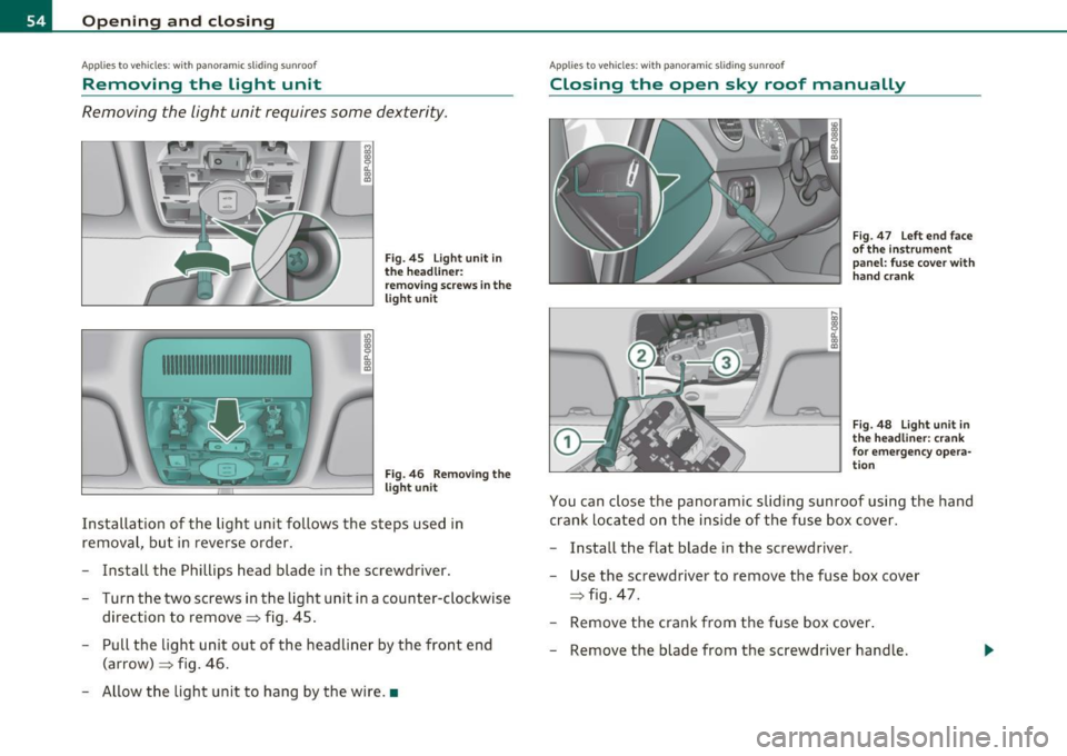
Removing the light unit requires some dexterity .
1111111111111111111111111111111
.,
~ CL ., m
"' ~ CL ., m
Fig. 45 Light unit in
t he headliner:
removing screws in the
light unit
Fig. 46 Removing the
light unit
Installation of the light unit follows the steps used in
removal, but in reverse order.
- Install the Phillips head blade in the screwdriver.
- Turn the two screws in the light unit in a counter-clockwise direction to remove~ fig. 45.
- Pull the light unit out of the headliner by the front end
(arrow) ~ fig. 46 .
- Allow the light unit to hang by the wire. •
Applies to vehicles : w ith panoramic sliding sunroof
Closing the open sky roof manually
Fig. 47 Left end face
of t he inst rument
panel: fuse cove r wit h
hand crank
F ig. 48 Lig ht unit in
t h e hea dliner : cran k
for emergency opera
t io n
You can close the panoramic sliding sunroof using the hand
crank located on the inside of the fuse box cover .
- Install the flat blade in the screwdriver .
Use the screwdriver to remove the fuse box cover
~ fig . 47 .
- Remove the crank from the fuse box cover .
Remove the blade from the screwdriver handle .
Page 57 of 320
- Install the end of the screwdriver handle onto the short side of the crank to help you turn it~
page 54, fig. 47 (D.
- Push the long end of the crank@~ page 54, fig. 48 all
the way into the hexagonal hole ®·
- Hold the crank down and turn it with the screwdriver
handle to close the roof.
- Install the light unit first and then the glass. For installa
tion , reverse the removal sequence.
- Return the crank to its location in the fuse box cover
~ page 54, fig. 47 and install the cover .
- Have the problem corrected .
[I) Tips
• To turn the crank for emergency closing more easily, yo u should
use the screwdriver handle as an aid . First, remove the screw driver
from the handle, then push the handle onto the crank.
• The crank should be turned slowly; turning it quickly only
increases the effor t required. •
Controls and equip
ment Safety first
Op
ening and closing
Vehicle care Technical data
Page 106 of 320
1111....__w __ a _r_ m __ a_n_ d_ c_ o _ l_d _______________________________________________ _
• Connect the connect ing cab le to the powe r cord .
• Atta ch t he exte nsion s co rd to the co nne ctor c able. A lw ay s use a
12 gauge or heav ie r heavy-duty extension cord that can be properly
gro unded to a three -prong Groun d Faul t C ircuit (G FI) w all o utle t a nd
is not longer than 100 ft (30 meters) .
• Alw ays pl ug th e p rehe ater into an 12 0 Vol t Grou nd Faul t Circui t
(GFI) wall o utlet t hat is properly protected against rain and other
mois ture . Neve r plug t he prehea ter in to a norm al ou tle t rega rdles s of
w het her it is grounded or not .
• Alw ay s dis con nect the co nne ct ing cable and close the cover
=> page 103, fig. 105 (D be fore starting the engine.
& WARNING
Using incorrect or damaged outlet and power cords, using elec
trical accessories incorrectly or ignoring safety precautions can lead to short circuits, accidents, injuries and life-th reatening elec
tric shocks.
• Always plug the preheater into a 120 Volt Ground Fault Circuit
( GFI) wall outlet that is properly protected against rain and other
moisture.
• Always check the fuse protection of the 120 Volt power source
before using the connecting cable.
• Always use a 12 gauge or heavier heavy-duty extension cord
that can be properly grounded to a three-prong GFI outlet. The
extension cord must not be longer than 100
ft (30 meters ).
• Always connect the cable to a 120 Volt outlet that is grounded
and protected from water .
• Check the cable for damage before every use. Never use a
damaged cable. It must be replaced. Please see your authorized
Audi dealer.
• Only use the cable provided*.
• Always remove the conne cting cable before starting the
engine.
& WARNING (co ntinued )
• Never attempt to alter or repair electrical components. •
Page 283 of 320
______________________________________________ F _u_s _e_ s_ a_ n_ d _ b _u_l_b _ s _ ___.fflll
Fuses and bulbs
Electrical fuses
Replacing fuses
A problem in the electrical system may be caused by a
blown fuse .
Fig. 193 Left cockpit:
f use pa nel cover
Fig. 19 4 Left s ide o f
engine compar tm ent:
' fuse cove r
Vehicle OP-eration
Fuse cov er on th e left end fac e of th e
instrum ent pan el
- Turn off the ignition and the affected electrical
consumers .
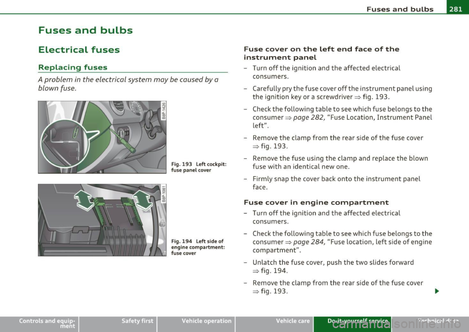
- Carefully pry the fuse cover off the instrument panel using the ignition key or a screwdriver=> fig. 193 .
- Check the following table to see which fuse belongs to the
consumer =>
page 282, "Fuse Location, Instrument Panel
left".
- Remove the clamp from the rear side of the fuse cover
=> fig. 193 .
- Remove the fuse using the clamp and replace the blown fuse with an identical new one .
- Firmly snap the cover back onto the instrument panel
face .
Fuse cover in engine compa rtment
- Turn off the ignition and the affected electrical
consumers.
- Check the following table to see which fuse belongs to the
consumer =>
page 284, "Fuse location, left side of engine
compartment" .
- Unlatch the fuse cover, push the two slides forward => fig. 194.
- Remove the clamp from the rear side of the fuse cover
=> fig. 193.
Vehicle care Do-it-yourself service iTechnical data
Page 284 of 320
llffll.,___F_ u_ s_e _ s_ a_n_ d_ b_u _ l_ b_ s _______________________________________________ _
-Remove the fuse using the clamp a nd replace t he blown
fuse w ith an identical new one .
- Push the two slides to t he rear=>
page 281, fig. 19 4.
Install the f use cov er ca ref ully to prevent wa ter from
enterin g.
The vario us electrical c irc uits are p rotect ed by fus es . The fuses are
clustered in a centralized unit . The unit is located behind the face
pane l at the end of the inst rument pane l. The crank for operat ing the
sunroof in case of a power failure is also stored behind the face panel
=1 page 53.
Two spare fuses and a st icker identify ing the fuses are located on the
inside of the fuse box cover.
You a re well advised to keep a supp ly of spa re fuses in your vehicle .
Fuses with the proper ampere ratings are avai lab le at your authorized
Audi dealer.
& WARNING
Do not repair fu ses and never replace a blown fuse with one that
has a higher amp rating . Th is can cause damage to the electric al
s y stem and a fire .
0 Note
If a new fuse burns o ut agai n af ter shortly h ave yo u have insta lled it ,
have the electrical system checked by your authorized Audi dealer.
[ i J Tips
• The following tab le does not list fuse locations that are not used.
• Some of the eq uipmen t items listed are option al or only available
on certain model configurations .
• Th e crank in the cover is used for eme rgency operation of the
powe r roo f*.•
Fuse Location, Instrument Panel left
Fuses which can be replaced.
Fig.1 95 C ockpi td ri ve r's
side: fuse pan el lay out
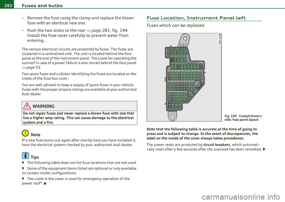
Note that the following table i s accurate at the time of going to
pres s and is subject t o change. In the event of discrepancies, the
label on the inside of the cover alway s takes pre cedence.
The power sea ts are p ro te cte d by circuit break ers, whi ch automa ti
cally reset after a few seconds after the over load has been remedied . ..,_
Page 286 of 320
lffll.,___F_ u_ s_e _ s_ a_n_d _b_u _ l_ b_s _______________________________________________ _
(I) Tips
• Whenever replacing a fuse, always consult the sticker on the
i ns ide of the fuse panel cover. It contains the most up-to-date infor
mation regarding the fuse arrangement . If in doubt , ask your autho
rized Audi Service advisor.
• Some of the equipment items listed are optiona l or only available
on certain model configurations. •
Fuse location, left side of engine
compartment
Fig. 196 Engine
compart ment: fuse
assignment
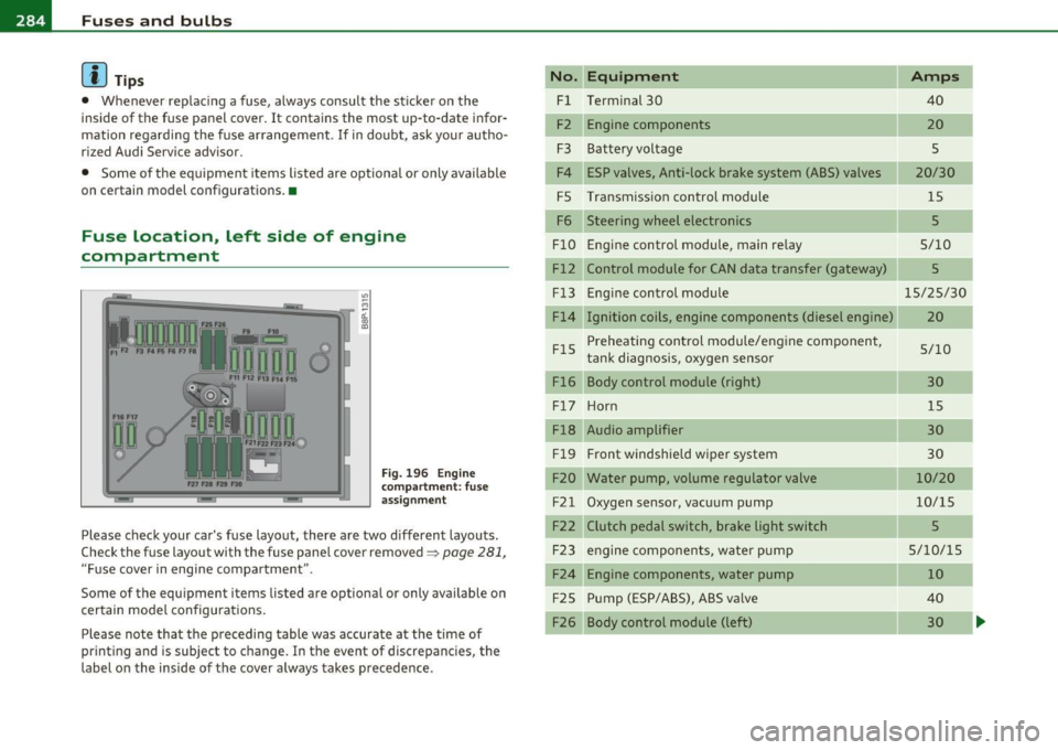
Please check your car's fuse layout, there are two different layouts.
Check the fuse layout with the fuse panel cover removed~
page 281,
"Fuse cover in engine compartment ".
Some of the equipment items listed are optional or only available on
certain model configurations .
Please note that the preceding table was accurate at the time of
printing and is subject to change . In the event of discrepancies, the
label on the inside of the cover always takes precedence .
No. Equipment
Fl Terminal 30
F2 Engine components
F3 Batteryvoltage
F4 ESP valves, Anti-lock brake system (ABS) valves
FS Transmission control module
F6 Steering wheel electronics
FlO Engine control module, main relay
Fl2 Control module for CAN data transfer (gateway)
Fl3
FlS
Fl6 Engine
control module
Ignition coils, engine components (diesel engine)
Preheating control module/engine component,
tank diagnosis, oxygen sensor
Body control module (right)
F l7 Ho rn
Fl8 Audio amplifier
Fl9 Front
windshield wiper system
F20 Water pump, volume regulator valve
F21 Oxygen sensor, vacuum pump
F22 Clutch pedal switch, brake light switch F23 engine components, water pump
F24 Engine components, water pump
F25 Pump (ESP/ABS), ABS va
lve
F26 Body control module (left)
Amps
40
20
s
20/30 15
5
5/10
5
15/25/30
20
5/10 30 15
30
30
10/20
10/15
5
5/10/15 10
40 30
Page 287 of 320
_______________________________________________ F_u _s_ e_ s_ a_ n_ d_ b_u _ l_ b _ s __ _
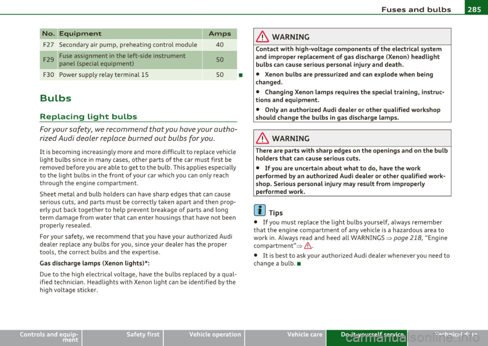
No. Equipment
F2 7 Secondary a ir pump, preheating contro l module
F 29 Fuse assignment in the left-side instrument
panel (special equipment)
F30 Power supply relay termina l 15
Bulbs
Replacing light bulbs
Amps
40
so
so
For you r safety, we recommend that you have your autho
ri zed Audi dealer replace burned out bulbs for you.
It is becoming increasingly more and more difficu lt to rep lace vehicle
light bulbs since in many cases, ot her parts of the car must first be
removed before you are able to get to the bu lb. This app lies espec ially
to the l igh t bu lbs in the front of your car whi ch you can o nly rea ch
through the engine compartment .
Sheet metal and bu lb holders can have sharp edges that can ca use
serious cuts, and parts must be correctly taken apart and the n prop
erly put back together to he lp prevent b reakage of parts and long
term damage from wate r that can enter housings that have not been
p roperly resealed.
For your safety, we recommend that you have you r authorized Audi
deale r replace any bu lbs fo r you, since your dealer has the proper
too ls, the cor rec t bu lbs and the expertise .
Gas dis charge lamp s (Xenon lights)* :
Due to the high electrical voltage, have the bulbs replaced by a qual
ified technician. Headlights with Xe non light can be iden tified by the
high voltage sticker.
Safety first
•
& WARNING
C ontact with high-voltag e components of the electrica l system
and improper replacement of g as discharge (Xenon ) headlight
bulb s can caus e serious personal injury and death .
• Xenon bulb s are pres surized and can explode when b eing
c hanged .
• Changing Xenon lamp s requir es the special training , instruc
tions and equipment.
• Only an authori zed Audi dealer or oth er qualified workshop
should change the bulbs in ga s di scharge lamp s.
& WARNING
There are parts with sharp edge s on the openi ngs and on the bulb
holde rs that can cau se se rious cuts.
• If you are uncertain about what to do, ha ve the work
performed b y an auth orized Audi de aler or oth er qualified work
s hop. Seriou s per sonal injur y m ay re sult from improperl y
p erformed w ork.
(I] Tips
• If you must replace the light bulbs yourself , a lways remember
that the engine compar tment of any vehicle is a hazardo us area to
work in. Always read and heed all WARNINGS=>
page 218, "E ngi ne
compa rtment" =>& .
• It is best to ask you r author ized Audi dealer whenever you need to
change a bu lb. •
Vehicle care Do-it-yourself service Technical data
Page 311 of 320
___________________________________________ A_ l:.. p _h _a_ b_ e_t _ic _a_ l_ in_ d _ e_x __ _
Fastening
Booster seats ............... ... .. 17
5
Convert ible child safety seats .. ..... 173
Infant seats ..................... 172
Fastening eyes . ................. .. .. 82
Flat tire Changing . .. ........... .. .... .. . 272
Floor mats ........... .... .......... 130
Fog lights, front ........... .... .. .. .. 58
Folding master key with remote control .. 38
Foot pedals .. .. ... ........ .. .... .. . 130
For the sake of the environment
Gasoline fumes and the environment 222
Letting your engine warm up ....... 107
Reducing engine noise by upshifting ear ly
8,9
Refueling . .. .. .. .. .. .. .. ........ 222
Saving fuel by upshifting early .. ... . 8, 9
Using the rear window defogger . ... . 102
Front airbags Description . ...... .. .. .. .. .. .... . 149
How they work .......... .. .. .. .. . 154
Front seats .. .. .. ................... 73
Adjusting . .. ... ........ ...... .. . 127
Adjusting the manual seats ......... 74
Child restraints in the front seat .... 147
Heated seats .................... 103
Fro ntal collisions and the laws of physics 136
Fuel Current fuel mileage .... .... ....... 21
Fu el gauge ........ ... .. ...... .. .. 10
Fuel supply too low . ... .. .. .... .... 34
Controls and equip
ment Safety first
Fuel
economy messages (efficiency program)
26
Fuel filler flap Unlocking the fuel filler flap by hand . 224
Fuel gauge .... .. ................. ... 10
Fuel range ............. .... .. .. .. .. . 21
Fuel supply
Additives .. ............... ...... 219
Blended gasoline .... .. .. .. ... .... 219
Fuel filler neck .. ........... .. .. .. 221
Fuel gauge . .... .... .. .. ... ....... 10
Fuel tank capacity ......... ... 10,221
Gasoline ...................... .. 219
Gasoline additives ................ 220
Octane rating ...... .............. 219
Recommendation ................ 219
Refuelling ... .. .... .. .. .... .. ...
222
Unlocking the fuel filler flap by hand . 224
Fuel tank
Capac ity ........................ 221
Capacity (gallons/liters) ........ ... . 10
Fuse arrangement ................ ... 282
Fuses Replacing ....................... 281
G
Gas discharge lamps ...... ........... 285
Gauges Eng ine coolant tern perature .......... 9
Fuel gauge .. ..... .. .............. 10
Speedometer ............ .. ... .... 10 Tachomete
r ... ... .... ........ ..... 8
Trip odometer .................... 10
Gear recommendation ................ 19
Gearshift indicator ................... 19
Gearshift lever .................... . 114
General illust ration
Instruments and controls ............
7
Generator
Warning/indicator lights ... .. ...... 15
Glossary of tire and loading terminology 246
Glove compartment . .. .. .. ...... ..... 92
Light . . . . . . . . . . . . . . . . . . . . . . . . 60, 61
Glow plug system Indicator light .................... 13
Warning light ...... ..... ... . ... .. 13
Gross Vehicle Weight Rating (GVWR) ... 295
H
Head restraints .......... .... .. .. .. . 128
Adjusting ................. ...... 128
Rear seats .. .. ................... 78
Headlight defective ... ...... ............... 36
Headlight range control defect ive . .. ...... ............... 35
Headlights ................. ... ...... 56
Front fog lights ................... 58
Switching off ... ..... .... ... .. .. .. 56
Switching on ................... .. 56
Xenon headlights . .. .... .... .. ..... 56
Heated rear window ..................... 102
Vehicle operation Vehicle care Do-it-yourself service Technical data