odometer AUDI A3 2011 Owner´s Manual
[x] Cancel search | Manufacturer: AUDI, Model Year: 2011, Model line: A3, Model: AUDI A3 2011Pages: 320, PDF Size: 75.79 MB
Page 10 of 320
Instruments and warning /indicator lights
Instruments and warning/indicator lights
Instruments
Instrument cluster and controls
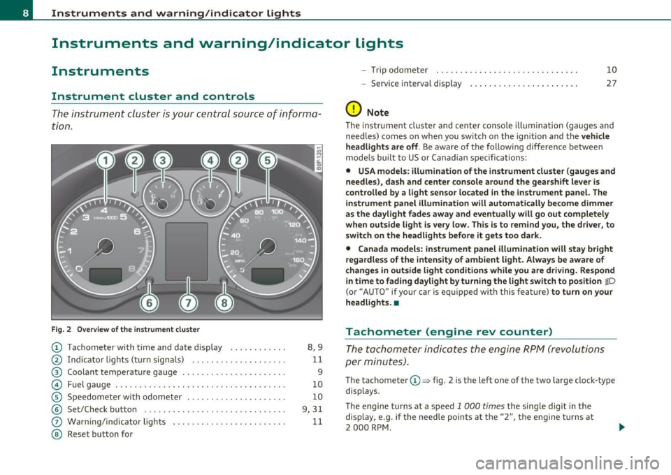
The instrument cluster is your central source of informa
tion.
Fi g. 2 O ver view of the in strum ent cluster
© Tachometer with t ime and date d is play ........... .
@ Indic ator light s (turn s igna ls) ....... ... . .. .. ... . .
® Coolant temperature gauge . .. .. .. .. .. .. ... .. ... .
© Fue l gauge . ... ... .. ... ..... ... ... .... ... . .. .. .
© Speedomete r with odometer ...... .... .. .. .. . ... .
© Set/Check bu tton ....................... ...... .
(j) Warning/ind icator lights . .... .. .. .. . ... ... .. ... .
@ Reset button fo r
8,9
11
9
10
10
9, 3 1
11
- Trip odometer
- Service in terval disp lay
(D Note 10
27
T
he instrument cluster and center conso le illum ination (gauges and
need les) comes o n when you sw itch on the ign ition and the
vehicle
headlights are off .
Be aware of the following d ifference between
mode ls built to US o r Canadian specifications :
• USA models : illumination of the instrument cluster (gauges and
needles), da sh and c enter console around the g earshift lever is
controlled by a light sensor located in the instrument panel. The
instrum ent panel illumination will automat ically become dimmer
as the d aylight fades awa y and eventually will go out completely
when out side light i s very low . Th is is to remind you, the driver , to
switch on the headlights before it gets too dark .
• Canada models: instrument panel illumin ation will stay bright
r egardless of the intensity of ambient light. Always be awa re of
change s in out side light condition s while you are driving. Re spond
i n time to f ading daylight by turning the light sw itch to position
j D
(or "AUTO " if your car is eq uipped w ith this fea ture) to turn on your
headlights. •
Tachometer (engine rev counter)
The tachometer indica tes the engine RP M (revolutions
per minutes) .
The tachomete r© ::::, fig . 2 is the left one of the two large clo ck-type
displays .
The engine turns at a speed 1 000
times the single digit in the
display, e .g . if the need le points at the "2", the engine tu rns at
2 000 RPM .
Page 12 of 320
Instruments and warning/indicator lights
Engine cold
As long as the need le remains at the lef t en d of the gauge, the engine
s till has not reac hed its operati ng te mperature . Avoid hig h eng ine
speeds, heavy engine loads a nd heavy throttle.
Normal temperature
W hen the eng ine has reached its operating temperature, the need le
w ill move into the middle of the gauge and rema in there . If the
engine is working ha rd at high outsi de temperatures, the needle may
tur n further to the rig ht. Thi s is no cause fo r concern as long as the _F_
wa rning light in the i nstr ument cluster does not ill uminate.
Wh en the _;_ w ar ning light sta rts to fla sh, thi s can mea n one of two
things : either the coolant
temperature is too h igh, or t he coolant
level is too low => page 32.
& WARNING
• Always observe the warning in=> page 218, "Engine com part·
ment " before opening the engine hood and checking the engine
c oolant level.
• Never open the engine hood if you see or hear steam, or if you
see engine coolant dripping from the engine compartment. You
could burn yourself. Let the engine cool off first so that you cannot
hear or see any steam or engine coolant.
0 Note
• Moun ting addition al lights or accessorie s in fron t of the a ir inlets
red uces the cooling effect of the radiator. At high o utside tempera
tu res o r high eng ine lo ad, t he e ngine cou ld over heat .
• The front spoi ler has been designed to prope rly d istribute the
c oo ling a ir w hen the vehicle is moving. If the spoiler is d amaged, this
co uld reduce the coo ling effect and the eng ine could t hen overheat.
Ask your au thor ized A udi d ealer for assist ance .•
Fuel gauge
T he f uel gauge wo rks only whe n the ignition is on.
W hen the nee dle rea ches the red area, t he war ning ligh t in t he ins tru
ment cl uster will illum inate=>
page 34 . This mea ns you have
app roximate ly 1.8 gallons (7 liters) of f uel left in t he tank.
Time to
refuel!
The tota l tan k capacity of your vehicle is listed in => page 296 , "Data".
0 Note
Never run the ta nk completely d ry ! An irregular s upply of f uel can
c a us e eng ine mi sfir ing and f uel could ente r into t he e xhaus t system.
T he catalyt ic converter could the n overheat a nd be damaged. •
Speedometer with odometer
The spee do meter sh o ws you the ve h icle s pee d, an d th e
o do met er sho ws yo u ho w many mile s (k il om eters) you
have d riv en .
Fig. 4 Spee dometer
close-up : odometer
di splay
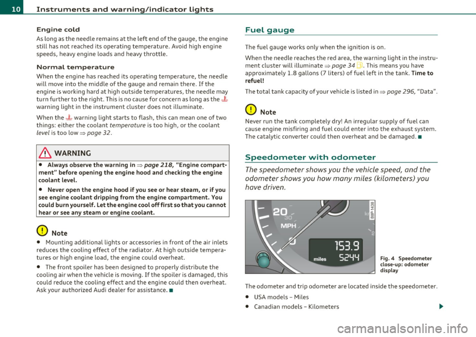
The o dometer and tri p odometer are located inside the speedomete r.
• USA mo dels - Mile s
• Canad ian models -Kilometers
Page 13 of 320
Lower odometer
The lowe r odometer shows the total number of mi les (k ilometers)
driven .
Upper odometer (trip odometer)
The upper odometer shows the total number of m iles (kilometers)
driven since you last reset the odometer back to zero . Yo u can use th is
odometer when you want to keep track of how many m iles (k ilome
ters) you have dr iven for a sing le trip or er rand. The last dig it indicates
1 /10 of a mi le ( 100 metres) . You can set the trip odome ter back to
zero by pressing the reset button=>
page 10, fig. 4.
Malfunction message
If there is a ma lfunction somewhe re in the instr ument cl uster, dEF
will appear in the trip odometer and will stay on. Contact you r autho
r ized A udi dea ler to have the problem corrected .
Immobilizer
When the ignition is switched on, the da ta on the igni tion key are
scanned automatically.
If an una uthorized key was used,
SAFE is disp layed continuous ly in
t he o dome ter di sp la y field. The vehicle ca nnot be operated
=> page 40.
[ i J Tips
• The d ig ita l clock and the odometer are turned on for about 30
seconds when the driver's do or is ope ned.
• When the ignition is turned off, t he odomete r reading and the
dig it al cl ock wi th date di sp la y can be sw itche d on for abou t
30 seconds by press ing the knob::::;,
page 8, fig. 2 @ . •
Con tro ls a nd e quip
m en t Vehicle
OP-eration
Instruments and warning /indicator lights
Warning/indicator lights
Overview
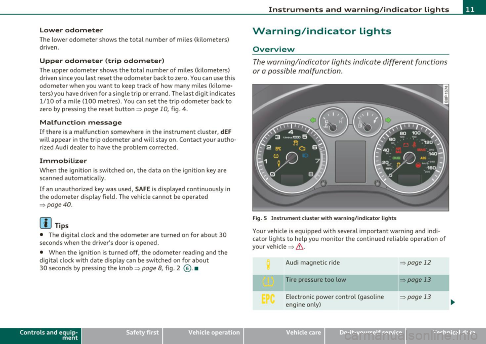
The w arni ng/in dicator lights ind icate differ ent fun ctions
o r a po ssible m alfunc tio n.
Fig. 5 In strument clu ster w ith warn ing /ind ica tor light s
Your vehicle is equipped with several important warning and indi
c ato r lights to help yo u m onito r th e con tinued re liable operat io n o f
your vehicle ::::;,& .
Aud i ma gnetic ride
Tire pressure too low Electronic power control (gasoline
engine o nly)
=> page 12
=:> page 13
=> page 13
Vehicle care Do-it-yourselt service iTechnical data
Page 31 of 320
Speed warning 1: setting a speed Limit
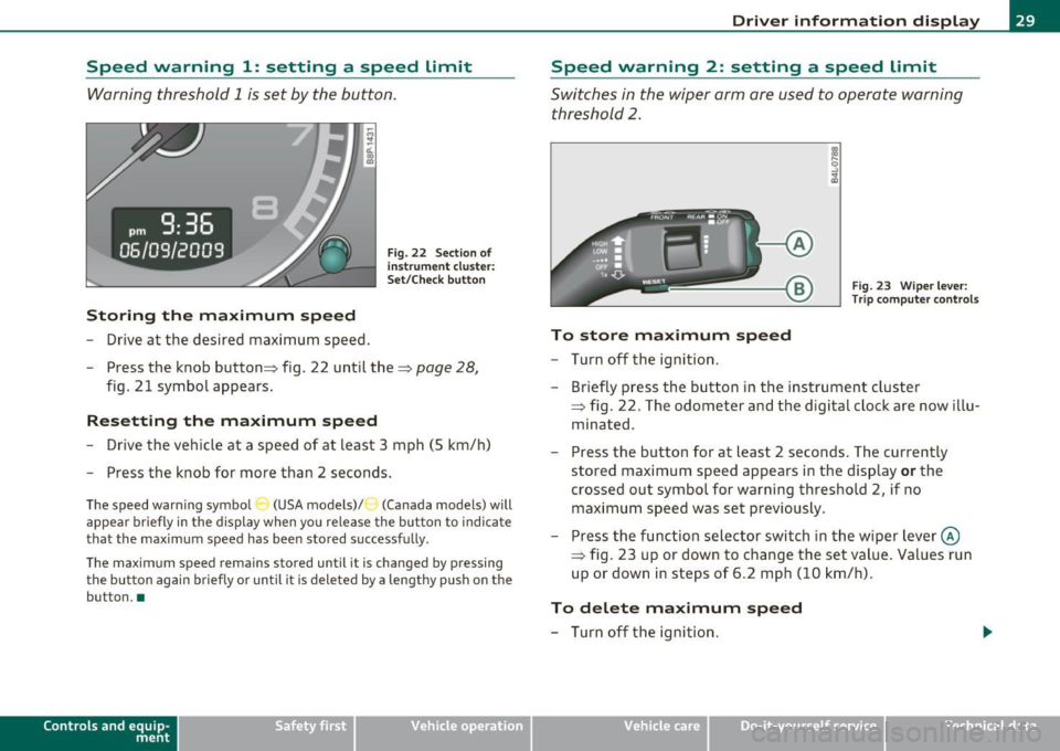
Warning threshold 1 is set by the button.
Storing the maximum speed
- Drive at the desired maximum speed.
Fig. 22 Section o f
in st rum ent cluster:
Set/Check button
- Press the knob button :::} fig. 22 until the :::} page 28,
fig. 21 symbol appears.
Resetting the maximum speed
- Drive the vehicle at a speed of at least 3 mph (5 km/h)
- Press the knob for more than 2 seconds.
The speed warning symbo l (USA models) /') (Canada models) will
appear briefly in the display when you release the button to indicate
that the maximum speed has been stored successfully .
The maximum speed remains stored until it is changed by pressing the button again briefly or until it is deleted by a lengthy push on the
button. •
Contro ls a nd e quip
m en t Vehicle
OP-eration
Driver information display
Speed warning 2: setting a speed Limit
Switches in the wiper arm are used to operate warning
threshold
2.
Fig. 23 Wiper lever:
Trip computer controls
To store maximum speed
- Turn off the ignition.
- Briefly press the button in the instrument cluster
=> fig. 22. The odometer and the d igital clock are now illu
minated .
- Press the button for at least 2 seconds. The currently
stored maximum speed appears in the display
or the
crossed out symbol for warning threshold 2, if no maximum speed was set previously .
- Press the function selector switch in the wiper lever@
=> fig. 23 up or down to change the set value . Values run
up or down in steps of 6.2 mph (10 km/h).
To delete maximum speed
- Turn off the ignition.
Vehicle care Do-it-yourselt service iTechnical data
Page 32 of 320
Driver info rmation d isplay
- Briefly press the button in the instrument cluster
=>
page 29, fig . 22. The odometer and the digital clock are
now i lluminated .
- Press the button for at least 2 seconds . The currently
stored maximum speed appears in the display.
- Press the reset button in the wiper lever@=>
page 29,
fig. 23 until the crossed out speed warning symbol for
warning th reshold 2 appears in the display.
A few seconds after the ad justment is completed, the illuminat io n for
the odometer and the digital clock will go out.
[ i J Tips
This warning thresho ld can also be contro lled through the trip
computer~
page 24, "Navigat ing the menu" .•
Warnings and symbols
Red symbols
A red symbol means DANGER
- P ull of the road and stop the vehicle .
- Turn off the engine.
- Check the malfunctioning syst em. Contact you r au tho-
rized Audi dealer or a qualified workshop for assistance.
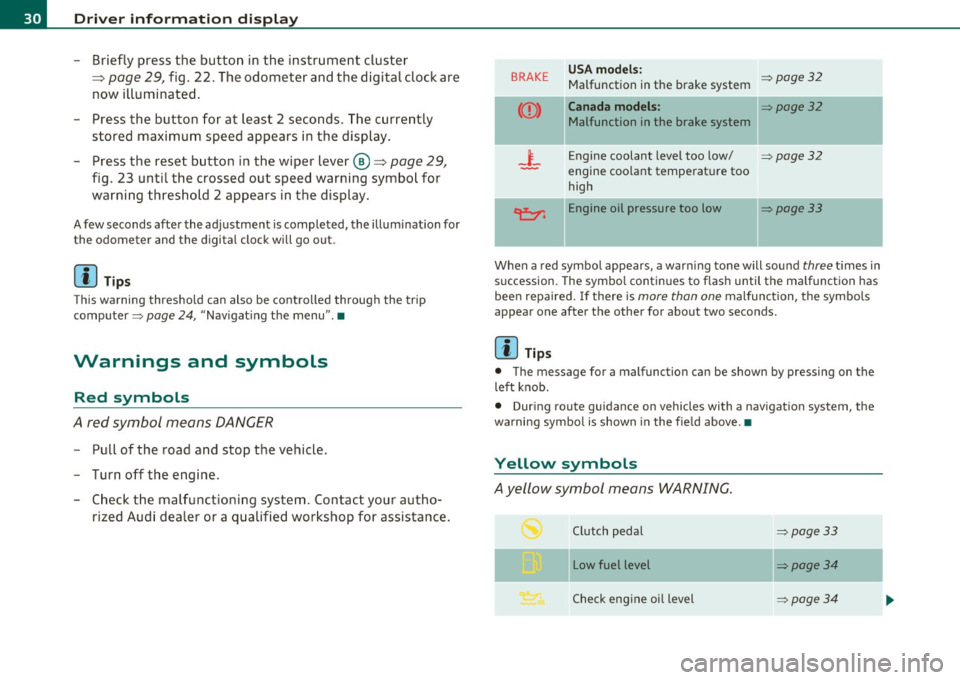
BRAKE USA models : ~page32 Malfunction in the brake system
Canada models : ~page32
Malfunction in the brake system
_i_ Engine coolant level too low/ ~page32
-engine coolant temperat ure too
high
~ Engine oil pressure too low ~page33
When a red symbo l appears , a warn ing tone will sound three t imes in
succession. The symbo l continues to flash until the malfunction has
bee n repaired. If there is
more than one malfunction , the symbols
appear one after the other for about two seconds.
[ i J Tips
• The message for a malfunction can be shown by pressing on the
left knob.
• During route guidance on vehicles with a navigat ion system, the
wa rni ng symbo l is shown in the fie ld above. •
Yellow symbols
Ayellow symbol means WARNING.
Clutch pedal ~page33
- -
Low fuel level ~page34
Check eng ine oi l level ~ page34
Page 309 of 320

------------------------------------------~A~ LE P '.!:h ~a~ b~e~ t~ic ~a~ l~ in~ d ~ e~x ~ _lffl'II
Coolant system ....... ... .. .. .. .. .. . 234
Cooling System
Expansion tank .................. 235
Cru ise control .............. ... ..... 110
Changing speed ................. . 111
Presetting your speed .......... .. . 111
Switching off ............. .. .... . 112
Switching on ........... ......... 110
Warning/indicator lights ... .... .... 14
Cup holder ............ ...... .. .. .. .. 89
Cup holders front ........ ...... .. .. .. .. .. .. .. 89
Current fuel mileage ................ .. 21
D
Damp ing
See Audi magnetic ride ......... ... 112
Data ....... .... ...... .. .... .. .. .. . 296
Data recorder ................. .. ... 188
Date display .. .. .. ............... .... . 9
Daytime running lights ............... . S6
Daytime running lights (Canada) ........ 56
Declaration of compliance Cell phone package ............ .. . 303
Electronic immobilizer ... .. .. .. .. . 303
Homel ink® un iversal remote control . 303
Remote control key ............... 303
Ti re pressure monitoring system ... . 303
def What does this mean when it appears in
the trip odometer display? ......... 10
Defective light bulb warn ing . .. .. .. .. .. 36
Controls and equip
ment Safety first
Defogg
ing the windows ....... .... ... . 98
Defrosting the windows ............... 98
Defrosting/defogging w indows ..... ... 101
Determining correct load limit . ...... .. 254
Diesel engine Add ing engine oil .. .... .. ......... 233
Changing engine oil .. .. ........... 233
Engine oil . ... .... .... ........... 233
Diesel fuel .. .................... ... 220
Diesel particulate filter. . . . . . . . . . . 34, 199
Digital clock . .. ............. .. .... .... 9
Setting the time ............ ....... 9
Digital compass . ................ ... . 71
Dimensions ..... .... ............... 295
Dipstick Reading the dipstick p roperly ..... .. 231
Direct Shift Gearbox Emergency release ............... 121
Distance .... .... .. .... .............. 22
Doors, power locks .... ... .. .. ........ 43
Driver information ................... 31
Driver Information System Menu display ............ ......... 22
Driver information system
Gearshift indicator ............. .. . 19
Menu button . ....... .... .. .. .. .. . 24
Open door or front lid wa rning .. .. .. . 18
Outside temperature display ........ 18
Red symbols ................... ... 30
Service interval display ............. 27
Setting . ................ .. .. .. ... 2s
Sound system display .. .. .......... 18 Trip computer
... ... ..... ... . ... .. 21
yellow symbols .. ................ . 30
Driver seat
See Seating position ...... ..... ... 126
Driving safely .. .. .. .. ............. . 124
Driving through water .... .... .. .. .. . 198
Duplicate key ...... . .. ............... 38
E
Efficiency program . ... .. .. ........... 25
Fuel economy messages ............ 26
Other equipment ... ............... 26
Elapsed time ... ...... ............. .. 21
Electrically heated front seats .. .... .. . 103
Electro-mechanical power assist ... 17, 193
Electronic differential lock (EDL) How the system works .. .... ...... 189
Warning/indicator lights ... .. ... ... 16
Electronic immobilizer . . . . . . . . . . . . 10, 40
Electronic power control
EPC warning/indicator light ......... 13
Electronic speed limiter ........ ...... . 20
Electronic Stability Program ... .... .. . 188
Electronic stabilization program (ESP)
Warning/indicator lights ..... .. .. .. 14
Emergency flasher Warning/indicator lights ... .. ... ... 14
Emergency flashers ... .. .. .... ....... 59
Emergency operation panoramic sliding sunroof ........ .. 53
Rear lid .......................... 46
Vehicle operation Vehicle care Do-it-yourself service Technical data
Page 311 of 320
___________________________________________ A_ l:.. p _h _a_ b_ e_t _ic _a_ l_ in_ d _ e_x __ _
Fastening
Booster seats ............... ... .. 17
5
Convert ible child safety seats .. ..... 173
Infant seats ..................... 172
Fastening eyes . ................. .. .. 82
Flat tire Changing . .. ........... .. .... .. . 272
Floor mats ........... .... .......... 130
Fog lights, front ........... .... .. .. .. 58
Folding master key with remote control .. 38
Foot pedals .. .. ... ........ .. .... .. . 130
For the sake of the environment
Gasoline fumes and the environment 222
Letting your engine warm up ....... 107
Reducing engine noise by upshifting ear ly
8,9
Refueling . .. .. .. .. .. .. .. ........ 222
Saving fuel by upshifting early .. ... . 8, 9
Using the rear window defogger . ... . 102
Front airbags Description . ...... .. .. .. .. .. .... . 149
How they work .......... .. .. .. .. . 154
Front seats .. .. .. ................... 73
Adjusting . .. ... ........ ...... .. . 127
Adjusting the manual seats ......... 74
Child restraints in the front seat .... 147
Heated seats .................... 103
Fro ntal collisions and the laws of physics 136
Fuel Current fuel mileage .... .... ....... 21
Fu el gauge ........ ... .. ...... .. .. 10
Fuel supply too low . ... .. .. .... .... 34
Controls and equip
ment Safety first
Fuel
economy messages (efficiency program)
26
Fuel filler flap Unlocking the fuel filler flap by hand . 224
Fuel gauge .... .. ................. ... 10
Fuel range ............. .... .. .. .. .. . 21
Fuel supply
Additives .. ............... ...... 219
Blended gasoline .... .. .. .. ... .... 219
Fuel filler neck .. ........... .. .. .. 221
Fuel gauge . .... .... .. .. ... ....... 10
Fuel tank capacity ......... ... 10,221
Gasoline ...................... .. 219
Gasoline additives ................ 220
Octane rating ...... .............. 219
Recommendation ................ 219
Refuelling ... .. .... .. .. .... .. ...
222
Unlocking the fuel filler flap by hand . 224
Fuel tank
Capac ity ........................ 221
Capacity (gallons/liters) ........ ... . 10
Fuse arrangement ................ ... 282
Fuses Replacing ....................... 281
G
Gas discharge lamps ...... ........... 285
Gauges Eng ine coolant tern perature .......... 9
Fuel gauge .. ..... .. .............. 10
Speedometer ............ .. ... .... 10 Tachomete
r ... ... .... ........ ..... 8
Trip odometer .................... 10
Gear recommendation ................ 19
Gearshift indicator ................... 19
Gearshift lever .................... . 114
General illust ration
Instruments and controls ............
7
Generator
Warning/indicator lights ... .. ...... 15
Glossary of tire and loading terminology 246
Glove compartment . .. .. .. ...... ..... 92
Light . . . . . . . . . . . . . . . . . . . . . . . . 60, 61
Glow plug system Indicator light .................... 13
Warning light ...... ..... ... . ... .. 13
Gross Vehicle Weight Rating (GVWR) ... 295
H
Head restraints .......... .... .. .. .. . 128
Adjusting ................. ...... 128
Rear seats .. .. ................... 78
Headlight defective ... ...... ............... 36
Headlight range control defect ive . .. ...... ............... 35
Headlights ................. ... ...... 56
Front fog lights ................... 58
Switching off ... ..... .... ... .. .. .. 56
Switching on ................... .. 56
Xenon headlights . .. .... .... .. ..... 56
Heated rear window ..................... 102
Vehicle operation Vehicle care Do-it-yourself service Technical data
Page 317 of 320
Alphabetical index -________________ fWI
Tire specifications ........ .. .. ... . 258 Transmission Vehicle Identification Number (VIN) ... . 294
Tread depth ....... .............. 256 6-speed . .. ................ ... .. 114
Vehicle jack .. ............... .. 270,276
Uniform t ire quality grading ....... . 260 Manual transmission .............. 114
Vehicle literature ... .......... ...... .. 4
Winter tires ..................... 261 S tronic transmission . ............. 115
Vehicle-care products .. .. ..... .... .. . 206
Tires and vehicle load limits ........... 253 Transport Canada ................... 133
Tir es and wheels Tread Wea r Indicator (T WI) .. .. ....... 256
w
Checking tire pressure ............. 252
Trip computer ......... .............. 21
Cold tire inflation pressure ......... 249
Trip odometer ... .... .. .............. 10 Warning light
Dimensions .... .... .. .. ......... 257
What does it mean when dEF appears in Tire pressure monitoring
system ... .. 36
General notes ........... .... .. .. . 245
the trip odometer disp lay? .. .. .. .. . 10 Wa
rning lights . ...... ............. 8 , 11
Glossary of tire and loading terminology .
246
New tir es and wheels .......... .. . 257 Turn
sign als ... .. ... ........ ...... ... 59
Warning/indicator lights ........ .. . 14 Red symbols in the center display
.. .. 30
Yellow symbols in the center display . . 30
Warning/indicator l ights
Replacing .............. ...... .. . 258
Snow chains .............. .. .. ... 262
Tires and vehicle load limits .. .. .... 253
Wheel bolts ................ .. ... 263
Winter tires ..................... 261
u
Undercoating ... .... .... ........... 213
Unfastening safety belts ............. 142
Unidirect iona l tires ...... ... ......... 245 Airbag system ......
.......... .. .. 15
Anti -lock brake system (ABS) ........ 16
Brake system ..................... 15
Cruise control .................... 14
Electronic power control ... ......... 13
Tires/Wheels
Low aspect ratio tires ............. 264
Tir e pressure mon itoring system 13, 264
Torn or frayed safety belts ......... .. . 138 Uniform tire quality grading
.... ...... 260
Unlocking Power locking switch ............ .. . 44
Rear lid ................. .. .... ... 45 E
lectronic stabilization program (ESP) 14
Engine malfunction (diesel engine) ... 13
Generator . .. .... .. .... ........... 15
Glow plug system .. ............... 13
Touch-up paint ................ .. .. . 210
Remote control .. ... .... .......... 42 High beam
.. ..................... 14
T owing
Front eyelet ..................... 290 Using the fo
ld-out key .. .. .......... 43 Malfunction
Indicator Lamp (MIL) .... 14
Parking brake .. ...... .... ... . ... .. 15
Rear eyelet ...................... 290
T ow truck procedures ... .......... 289
V
Safety belt ................ ....... 15
Tire pressure monitoring system . .. .. 13
TPMS Vanity mirror ................
.... ... . 63 T
urn s ignals .............. ...... .. 14
Tire pressure monitoring system .... 265 Vehicle battery Warranty coverages
................. 299
Trailer towing ............. ...... .. . 202 Stationary .
.. .. ...... ........... 239 Washer
reservo ir ............ ... .. .. . 243
Operating instructions ......... .. . 203 Vehicle electrical system .. ............ 15 Wash
ing .................... ... ... 206
Tech nical requirements ....... 202, 203
Vehicle identification ........ .. .... .. 294 Automatic car wash
.......... ..... 207
Trailer towing tips .... ... .. .. ... .. 204
Vehicle identification label ............ 294 by hand .........
.. .. ...... .. .. . 207
Controls and equip
ment Safety first Vehicle operation
Vehicle care Do-it-yourself service Technical data