radio AUDI A3 2012 Owner´s Manual
[x] Cancel search | Manufacturer: AUDI, Model Year: 2012, Model line: A3, Model: AUDI A3 2012Pages: 280, PDF Size: 70.11 MB
Page 11 of 280
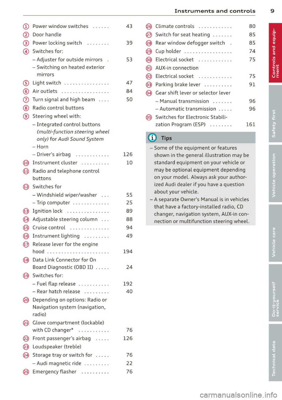
(!) Power window switches
@
®
©
Door handle
Power locking switch
Switches for:
- Adjuster for outs ide mirrors
- Switching on heated exter ior
mirrors
® L ight switch ............... .
® Air outlets ............ .... .
(J) Turn signal and high beam
@ Radio control buttons
® Steer ing wheel w ith:
- Integ rated control buttons
(multi -function steering wheel
only)
for Audi Sound System
- Horn
- Drive r's airbag ........... .
@ Instrument cluster .. ... .. .. .
@ Radio and telephone control
buttons
@ Sw itches for
- Windsh ield wiper/washer
- Trip computer ..... ... .. .. .
@ Ign ition lock .............. .
(8) Adjustable s teer ing column .. .
@) Cruise control ............. .
@) Inst rument lighting ........ .
@ Release lever for the engine
hood .... .. ... ..... ... .. .. .
@ Data Link Connector for On
Board Diagnostic (OBD II)
@ Sw itches for:
- Fuel flap release
43
39
53
47
84
so
126
10
55
25
89
88
94
49
194
24
192
- Rear hatch re lease . . . . . . . . . 40
@ Depending on opt ions: Rad io or
N avigation system (nav igat ion,
r adio)
@ Glove compartment ( lockable)
with CD changer * . . . . . . . . . . . 76
@ Front passenger's a irbag
@ L oudspeaker (treble)
~ Storage tray or sw itch for
126
76
- Audi magnet ic r ide . . . . . . . . . 22
@) Emergency flasher . . . . . . . . . . 76
Instrument s and control s 9
@ Climate controls .. .. .. ..... .
@ Switch for seat heating ...... .
@ Rear window defogger switc h
@ Cup ho lder ....... .. .. ..... .
@ Electr ica l socket .. .. .... ... .
@ AUX -in connect ion
@ E lectr ica l socket ........... .
@) Pa rking brake lever .... .. .. . .
@ Gear shift lever or selector lever
- Manual transmission ...... .
- Automatic transmission .... .
80
85
85
74
75
75
91
96
96
@ Switches for Electronic Stabili
z ation P rog ram (ESP)
161
@ Tips
- Some of the equ ipment o r features
shown in the genera l ill ustrat ion may be
standard equ ipment on your vehi cle or
m ay be opt ional eq uipment depending
on your model. A lways ask your author
ized Aud i dea le r i f you have a quest ion
about your vehicle .
-A separate Owner's Manual is in vehicles
that have a factory-installed radio, CD
change r, nav igat ion system, AUX-in con
nection or multifunction steering wheel.
Page 25 of 280
Driver information
display
Introduction
Introduction
The Driver information display inside the in
strument cluster provides you, the driver,
with important information.
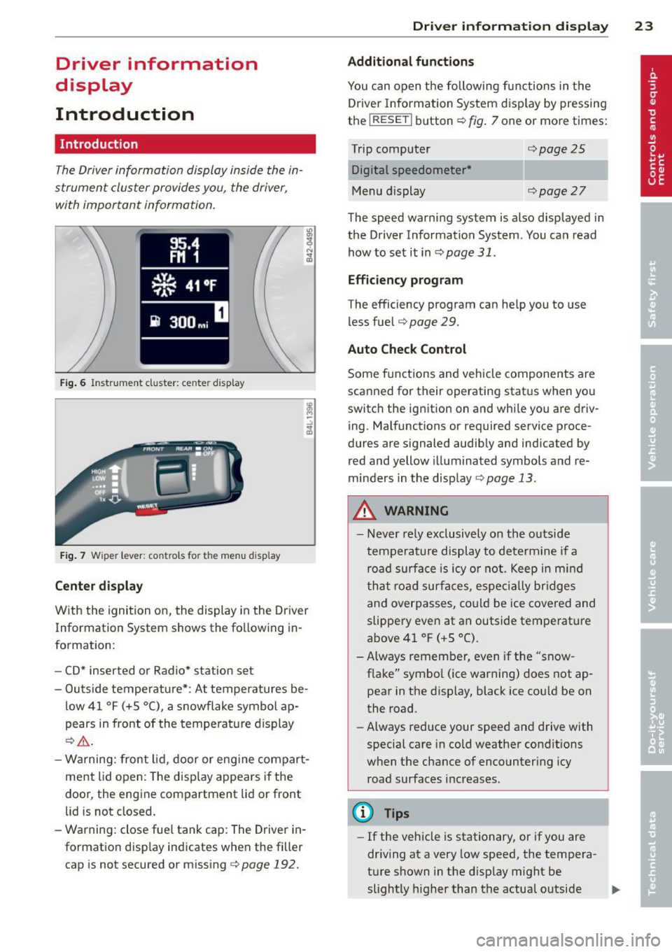
Fig. 6 Instr ument cluster: ce nte r dis play
Fig. 7 Wiper lever: controls fo r the menu d ispl ay
Center display
With the ignition on, the display in the Dr iver
Information System shows the fo llowing in
formation:
- CD* inserted or Radio* station set
- Outs ide temperature*: At temperatures be-
low 41 °F (+5 °C), a snowflake symbol ap
pears in front of the temperature display
¢_&. .
-Warning: front lid, door or eng ine compart
ment lid open: The disp lay appears if the
door, the engine compartment lid or front
lid is not closed.
- Warning: close fue l tank cap: The Driver in
formation disp lay indicates when the filler
cap is not secured or missing c>
page 192.
Driver information display 23
Additional functions
You can open the following functions in the
Driver Information System display by pressing
the
I RESETI button ¢ fig. 7 one or more times:
Trip computer Digital speedometer *
Menu display
¢page25
¢page27
The speed warning system is also displayed in
the Driver Information System. You can read
how to set it inc>
page 31.
Efficiency program
The efficiency program can help you to use
les s fuel
c> page 29.
Auto Check Control
Some f unctions and veh icle components are
scanned for their operating status when you
switch the ignition on and while you are driv
ing. Malfunctions or required service proce
dures are s ignaled audibly and indicated by
red and yellow illuminated symbols and re
minders in the display
¢page 13.
A WARNING
- Never rely exclusively on the outside
temperature display to determine if a
road surface is icy or not . Keep in mind
that road surfaces, especially bridges
and overpasses, could be ice covered and
slippery even at an outside temperature
above 41 °F (+S °C).
- Always remember, even if the "snow
f lake" symbo l (ice warning) does not ap
pear in the display, black ice could be on
the road.
- Always reduce your speed and drive with
special care in cold weather conditions
when the chance of encountering icy
road surfaces increases.
(D Tips
-If the vehicle is stationary, or if you are
driving at a very low speed, the tempera
ture shown in the display might be
slightly h igher than the actual outside .,,.
Page 38 of 280
36 Openin g and clo sing
in the cover. Correct po larity is shown on the
cover .
.. Place the cover with the new battery on the
key base and press both parts together.
@ For the sa ke of the environment
Dispose of dead batteries properly so as
not to po llute the environment.
(D Tips
The replacement battery must be the
same specification as the original.
Electronic immobilizer
The immobilizer helps to prevent unauthor
ized use of your vehicle .
A computer chip inside your key automat ica lly
deactivates the e lectronic immobilizer when
you insert the key in the ignition lock . When
you remove the key from the ignition lock, the e lectronic immobilizer is a utomatica lly acti
vated once again.
@ Tips
- The vehicle cannot be started if an unau
thorized key is used. The vehicle may not
start if another radio device such as a key
for another vehicle or transponder is lo
cated on the key ring.
- For Declaration of Compliance to United
States FCC and Industry Canada regula
tions
¢ page 262.
Power locking system
General description
The power Locking system Locks or unlocks all
doors and the rear lid simultaneously.
The power lock ing system in your veh icle in
corporates the fo llow ing funct ions:
- Central locking function
- Remote control feature¢
page 35.
- Anti-theft alarm system ¢ page 42.
All the doo rs and the rea r lid a re locked by the
central locking system when you lock the vehi
cle .
T he unlo ck ing and locking mode * can be
changed in the drive r information system
¢page 27.
Unlocking the vehicle
You can unlock t he vehicle from outside either
by us ing the remote contro l
or by inserting
and tu rning the key in the driver's door lock.
When you
unlock your vehicle:
- The ant i-theft a larm system is deactivated
b riefly .
- The vehicle i nte rio r lights i llum inate fo r ap
proxima tely 30 seconds .
- All turn s ignal lights w ill flash tw ice when
the ca r is u nlocked.
- After unlocking the vehicle, you have 30 sec
onds to open a door or the rear lid. After 30
seconds, the vehicle automat ically locks and
the anti -t h eft alarm system act ivates ag ain.
The rear lid can be locked o r unlocked either
by us ing the remote cont ro l
or by inserting
and tu rning the key in the drive r's door lock.
Unlocking the vehicle wi th the remo te contro l
c;:::::::5 will only unlock the rear lid, to open i t , the
lid handle needs to be pressed.
Locking the vehicle
You can lock the veh icle from outs ide either by
u sing the remote con trol
or by inse rting and
tu rning the key in the drive rs 's door lock .
When you
lock the veh icle:
- All doors a nd the rear lid are loc ked.
- All turn s ignal lights will flash once when
the car is locked.
- The ant i- theft a larm system is activated .
The horn of the anti-theft alarm system w ill
sound and the ant i-theft a la rm system read
iness l ight , loca ted in the center of the in
s trumen t panel be low the w indshield on the
r ight side of the ai r vent , will start to blink.
- The vehi cle i nte rior ligh ts turn
off. .,.
Page 40 of 280
38 Openin g and clo sing
The remote controls a llows you to:
- lock or unlock the veh icle
- selectively unlock the rear lid.
The turn signals will flash briefly whenever
you lock or unlock the vehicle. Also, the interi
or light will come on or go off whenever you
open or close the dr iver's door .
The transmitter and battery are located in the
head of the remote control. The receiver is lo
cated inside the vehicle . The maximum effec
tive range depends on seve ral things . Remem
be r, if the battery is weak, the effective range
dec reases.
The remote -control key conta ins a fold -out
key that you can use to man ually lock or un
lock the v ehicle and to sta rt the e ng in e.
If you need to replace the remote contro l, or if
you need to have it repaired, you must see
your author ized Audi dealer . Only then can
you use the key again .
_& WARNING
Read and follow all WAR NIN GS c> &. in
G eneral descrip tion on page 37.
@ Tips
- The remote cont rol key is automat ical ly
deact ivated when th e ignition is sw itch
ed on.
-
- The op eration of the remote cont ro l key
c a n be tempo rarily disrupted by in terfer
ence from transmitters in t he vicin ity o f
th e veh icle work ing in t he same frequen
cy r ange (e .g . a ce ll phone, radio equip
ment).
- In order to make sure the locking func
tion is workin g, you shou ld always keep
you r eye on the vehicle to make sure it is
p roper ly loc ked.
- Do not use the remote control if you are
i nside t he car, ot herwise you may unin
tentiona lly lock t he ve hicle, and then you
would set off the anti-theft alarm when
you try open a door . In case this happens
anyhow, push the unlock button@ . - U
se the panic function on ly if yo u are in
an emergency situation .
Resetting the remote control
The remote control must be rese t if the vehi
cle does not unlock.
• Press t he u nlock button@ on the remote
cont ro l.
.. Man ually un lock the driver's door lock with
the mechanica l key within 30 seconds .
.. Press either the lock-
tD or the unlock @ but
ton to complete the reset seq uence.
Doors, power Locks
Operating the locks with the fold-out
key
To lock and unlock the vehicle from the out
side, turn the key in the lo ck of the driver 's
door .
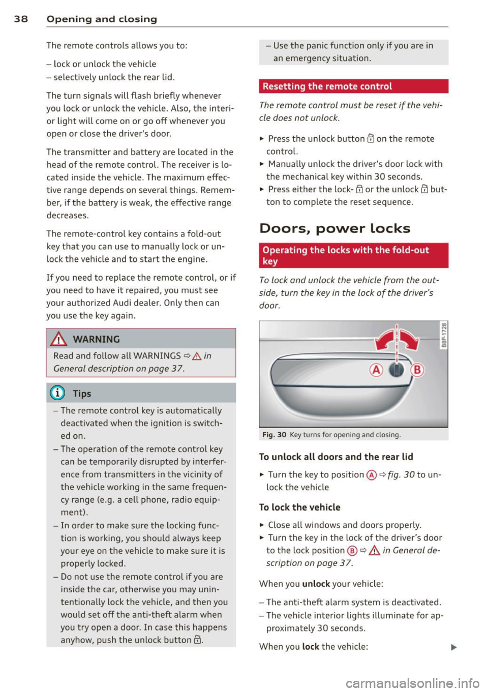
Fig. 30 Key turns for openi ng and closing.
To unlock all door s and the rear lid
.. Turn the key to position @ c> fig. 30 to un-
lock the vehicle
To lock the vehicle
,.. Close a ll win dows and doors pro perly.
.. Turn the key in the lock of the d river's door
to the loc k pos it ion
@ c> A in General de
scription on page 3
7.
When you unlock yo ur vehicle:
- The ant i-theft alarm system is dea ctivated.
- The vehicle i nterior lights illum inate fo r ap-
proximately 30 seconds .
When you
lock the vehicle:
Page 138 of 280
136 Airbag system
airbag system and prevent that system from
working properly in a collision.
There are some important things you have to know to make sure that the effectiveness of
the system will not be impaired and that dis
carded components do not cause injury or pol
lute the environment.
.&_ WARNING
Improper care, servicing and repair proce
dures can increase the risk of personal in
jury and death by preventing an airbag
from deploying when needed or deploying an airbag unexpectedly:
- Never cover, obstruct, or change the steering wheel horn pad or airbag cover
or the instrument panel or modify them
in any way.
- Never attach any objects such as cup
holders or telephone mountings to the
surfaces covering the airbag units.
- For cleaning the horn pad or instrument
panel, use only a soft, dry cloth or one
moi5tened with plain water. Solvent5 or
cleaners could damage the airbag cover
or change the stiffness or strength of the
material so that the airbag cannot de
ploy and protect properly.
- Never repair, adjust, or change any parts
of the airbag system .
- All work on the steering wheel, instru
ment panel, front seats or electrical sys
tem (including the installation of audio
equipment, cellular telephones and CB
radios, etc .) must be performed by a
qualified technician who has the training
and special equipment necessary.
- For any work on the airbag system, we
strongly recommend that you see your authorized Audi dealer or qualified work
shop.
- Never modify the front bumper or parts
of the vehicle body .
-Always make sure that the side airbag
can inflate without interference:
- Never install seat covers or replace
ment upholstery over the front seat- backs that have not been specifically
approved by Audi.
- Never use additional seat cushions that
cover the areas where the side airbags
inflate.
- Damage to the original seat covers or
to the seam in the area of the side air
bag module must always be repaired
immediately by an authorized Audi
dealer .
- The airbag system can be activated only
once . After an airbag has inflated, it
must be replaced by an authorized Audi
dealer or qualified technician who has
the technical information, training and
special equipment necessary.
- The airbag system can be deployed only
once. After an airbag has been deployed,
it must be replaced with new replace
ment parts designed and approved espe
cially for your Audi model version. Re
placement of complete airbag systems
or airbag components must be per
formed by qualified workshops only. Make sure that any airbag service action
is entered in your Audi Warranty
& Main
tenance booklet under
AIRBAG REPLACE
MENT RECORD .
@ For the sake of the environment
Undeployed airbag modules and preten
sioners might be classified as Perchlorate
Material - special handling may apply, see
www .dtsc .ca.gov/hazardouswaste/per
chlorate. When the vehicle or parts of the restraint system including airbag modules
and safety belts with pretensioners are
scrapped, all applicable laws and regula
tions must be observed. Your authorized
Audi dealer is familiar with these require ments and we recommend that you have
your dealer perform this service for you.
Page 169 of 280

Energy management
Starting ability is optimized
Energy management controls the distribution
of electrical energy and thus optimizes the
availability of electrical energy for starting the engine .
If a vehicle with a conventional energy system
is not driven for a long period of time , the bat
tery is discharged by idling current consumers
(e.g. immobilizer). In ce rtain c ircumstances it
can result in there being insuff icient ene rgy
avai lab le to start the engine .
Intell igent energy management in your vehi
cle hand les the d istribution of electrical ener
gy. Starting ab il ity is markedly improved and
the life of the battery is extended.
Basically, energy management consists of
batt ery di agno sis, idlin g current man ag e
m ent
and dyn ami c en ergy m anage ment .
Batter y diagnosis
Battery diagnosis continuously determines
the state of the battery . Sensors determ ine
battery vo ltage, battery current and battery
temperature. This dete rm ines the current
state of charge and the powe r of the battery.
Idling curr ent man agement
Idling current management reduces ene rgy
consumption while the vehicle is stand ing .
W ith the ignition switched off, it cont ro ls the
energy supply to the va rious electr ical compo
nents . Data from battery diagnosis is consid
ered.
Depending on the battery's state of charge,
i nd ividua l consumers are gradual ly t urned off
to prevent excess ive d ischarge of the bat tery
and thus maintain starting capability .
Dynamic en ergy management
While the vehicle is being driven, dynamic en
e rgy management dist ributes the energy gen
e rated according to the needs of the individu
a l components.
It reg ulates cons umption, so
that more electrical energy is not being used
Int ellig ent technolog y 167
than is being generated and ensures an opti
mal state of charge for the battery.
(0 Tips
- But even energy management canno t
negate the limits of physics . Consider
that the power and life of a battery are
limited .
- If starting ability is threatened, you are
informed by a warning
r:!) page 168,
Driver notification in the instrument
cluster display.
What you should know
The highest priority is given to maintaining
starting capability.
The battery is severe ly taxed in short -distance
driving, in city traffic and during the cold time
of year. Abundant electrical energy is re quired, but only a little is generated .
It is also
critical if the engine is not running and electri
cal components are turned on . In this in
stance energy is be ing consumed but none is
being generated.
It is in precisely these situations that you will
notice energy management actively regulat
ing the d istribution of energy .
Vehicle stands for an e xtended peri od
If you do not drive your vehicle over a period
of several days or weeks, e lectr ical compo
nents are gradually cut back or switched off.
This reduces energy consumption and ma in
ta ins start ing capability over a longer period .
Take into considerat ion that when you unlock
your vehicle, some convenience functions, such as the remote key or power seat adjust
ment, may not be available . The conven ience
funct ions w ill be available again when you
tu rn on the ignition and start the engine .
With the engine turned off
If you listen to the radio, for example, w ith
the engine turned off, the battery is being d is-
charged.
~
•
•
Page 212 of 280
![AUDI A3 2012 Owner´s Manual 210 Check ing and filling
POS IT IVE E] and NEGATI VE [:] to NEGATIVE
(j ump sta rt pins)[:].
.. Switch on the charger.
• Make sure the charging rate is not over
6 amps.
� AUDI A3 2012 Owner´s Manual 210 Check ing and filling
POS IT IVE E] and NEGATI VE [:] to NEGATIVE
(j ump sta rt pins)[:].
.. Switch on the charger.
• Make sure the charging rate is not over
6 amps.
�](/img/6/40267/w960_40267-211.png)
210 Check ing and filling
POS IT IVE E] and NEGATI VE [:] to NEGATIVE
(j ump sta rt pins)[:].
.. Switch on the charger.
• Make sure the charging rate is not over
6 amps.
• Turn off the charger¢,&..
• Disconnect the charger cables.
• Connect both battery cables to the battery
i f necessary -
first plus, then minus.
The battery must not be opened!
¢ @ in Gen
eral information on page 207 .
Chargi ng the b attery
Only use chargers with a m ax im um cha rg in g
v oltage o f
14.8 V. The battery connecting ca
bles do not need to be disconnected. Do not
open the battery when charging.
Read all of the manufacturer's instructions for
the charger before charting the battery.
It is not necessary to remove the battery from
the engine compartment, and it is a lso not
necessary to disconnect the cables.
Normally, a battery should be charged at no
more than 10 percent of its rated capacity.
For example, a charging current of 4.5 amps
wo uld be used on a battery rated at 45 Ah.
Rated capacity of the battery in your veh icle is
listed on the battery housing .
The battery caps shou ld
not be opened when
cha rg ing a battery.
_& WARNING
Cha rging a battery can be dangerous.
- Never charge a frozen battery. It may ex
plode because of gas trapped in the ice .
Allow a frozen battery to thaw o ut first .
- Do not reuse batteries which we re fro
zen. They must be replaced. The battery
housing may have cracked and weakened
when the battery froze.
- Charge the battery in a we ll ventilated
area. Keep away from open f lame or elec
trical spark. Do not smoke. Hydrogen gas generated by the battery is explosive. -
To reduce the danger of exp losion, never
connect or d isconnect charger cab les
while the charger is operating.
- Fast charging a battery is dangerous and
should only be attempted by a compe
tent techn ic ian with the proper equip
ment.
- Battery acid that may sp ill dur ing charg
ing should be washed off with a solut ion
of warm water and baking soda to neu
tralize the ac id.
{[) Note
-Make sure that the gas venting hose is
always connected to the or iginal opening
on the battery s ide. Otherwise gasses or
battery acid could leak out.
- Never use a fast charger as a booster to start the engine. This will seriously dam
age sensitive electron ic components,
such as contro l units, re lays, radio, etc.,
as well as the batte ry charger.
- T he vehicle may be optionally equ ipped
w ith a gel battery, wh ich can only be
charged at a cons tant current-lim ited
voltage . To prevent damage to the bat
tery and the electronics system, a gel battery that is connected must under no
circumstances be charged with a quick
charger.
{!) Tips
- The vehicle battery must not be charged
with a standard small charger that pl ugs
into the outlet.
- Only charge the battery through the con
nections in the engine compartment.
Battery replacement
The new battery must hove the some specifi
cations as the old one.
Intelligent energy management in your vehi
cle is responsible for distributing the electri
ca l energy throughout your vehicle
¢
page 167. The intelligent energy manage-
ment system will keep the engine battery .,..
Page 215 of 280
-Never mount used tires on yo ur vehicle if
you are not sure of their "previous histo
ry." Old used tires may have been dam
aged even though the damage cannot be
seen that can lead to sudden tire failure
and loss of vehicle control.
Glossary of tire and loading terminology
Accessory weight
means the comb ined weight (in excess of
those standard items wh ich may be rep laced)
of automa tic tra nsmission, power steering,
power br akes, power w indows, power sea ts,
radio, and heater, to the ex tent that these
items are avai lab le as factory -installed equip
ment (whether installed or not).
Aspect ratio
means the rat io of the height to the w idt h of
the tire in percent. Numbers of 55 or lower in
d icate a low sidewall fo r improved s teer ing re
sponse and better overall handling on dry
pavement.
Bead
means the pa rt of the t ire t hat is made o f
s teel wires, wrapped o r rein force d by ply cor ds
and that is shaped to fit the r im.
Bead separation
means a b reakdown of the bond between
components in the bead.
Cord
means the strands forming the plies in the
tire.
Cold tire infl ation pressure
means t he tire pressure recommended by the
vehicle manufacturer for a t ire of a designated
size that has not been dr iven for more than a
couple of miles (kilometers) at low speeds in
the three hour period before the tire pressure
i s measu red or adjusted.
Tire s an d wheel s 213
-If you notice un usua l vibration or if the
veh icle pulls to one side when driv ing, a l
ways stop as soon as it is safe to do so and check the wheels and tires for dam
age.
Curb weight
mea ns the we ight of a motor ve hicle w it h
standard equipment in cl ud ing t he maximum
capa city of fuel, o il, and coolant, ai r cond i
tion ing a nd addi tional weig ht o f optiona l
equipment .
Extra load tire
means a t ire designed to operate at higher
loads and at highe r inflat ion p ressu res tha n
th e co rresponding standard tire. Extra load
tir es my be i dent ified as "XL", "xl", "EXTRA
L O AD", or "R F" on t he sidewall.
Gross Axle Weight Rating ("GAWR ")
mea ns the load-carry ing capac ity of a s ingle
axle system, measured at the tire-ground in
te rfaces.
Gross Vehicle Weight Rating ( "GVWR ")
means the maximum total loaded we ight of
the ve hicle.
Groove
means the space between two adjacent tread
ribs.
Load rating (code )
means the maximum load tha t a t ire is rated
to carry for a given inflation press ure. Yo u
may not find this information on all tires be
ca use it is not required by law.
Maximum load rating
me ans the load r ating for a tire at the maxi
mum pe rm issi ble inf lat ion pressure for that
ti re . •
•
...
Page 246 of 280
244 Fuses and bulbs
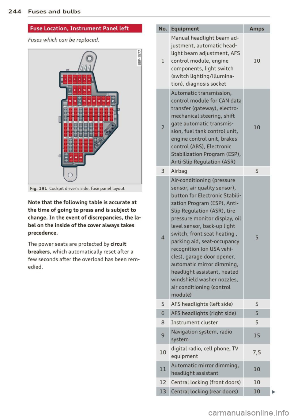
Fuse Location, Instrument Panel left
Fuses which can be replaced.
Fig. 191 Cockp it driver 's s ide: fuse pane l layout
Note that the following table is accurate at
the time of going to pr ess and i s subject to
change . In the event of d iscrepancies, the la
bel on the in side of the cover always take s
pr eceden ce .
The power seats are protected by circuit
break ers,
which automatically reset after a
few seconds after the ove rload has been rem
ed ied .
Equipment
Manua l head light beam ad
justment, a utomat ic head
light beam adjustment, AFS
1 co ntrol m odule, engine
components, light switch
(switch lighting/illumina
ti on), diagnosis socke t
2
3
4
5
6
8
9
Automatic transmission,
control module for CAN data
transfer (gateway), electro
mechanical steering, shift
gate automatic transmis
sion, fuel tank control unit,
engine control unit, brakes
control (A BS), Electronic
Stabili zation Program (ESP) ,
Anti-Slip Regulation (ASR)
Air bag
Air-conditioning (pressure
sensor, air quality sensor), button for Electronic Stabili
zation Program (ESP), Anti
Slip Regulat ion
(ASR), tire
pressure monitor display, oil
level senso r, back-up ligh t
s w itch, front se at he ati ng ,
p ark ing aid, sea t-occupancy
recognition (on USA vehi
cles), garage door opener,
automa tic mirror dimming,
headlight assistant, heated
windshield washer nozzles, air conditioning (control
module)
AFS headlights ( left si de)
AFS headlights (right side) Instr ument cluster
Navigation system, radio
system
1 0 digital
radio, cell phone, TV
equipment
11 Automatic mirror dimming,
headlight assistant
12 Central lock ing (front doors)
Central locking ( rear doors)
Amps
10
10
5
5
5
5
5
15
7 ,5
10
10
10
Page 251 of 280

CD Note
-Applying a higher vo ltage booster bat
tery will cause expensive damage to sen
sitive electronic components, such as
control units, relays , radio, etc.
- There must be no e lectrica l contact be
tween the vehicles as otherwise current
could already start to flow as soon as the
pos itive(+) terminals are connected.
- Improper ly connected jumper cables can
cause substantial damage to the electri
ca l system of the vehicle .
(D Tips
-The discharged battery must be properly
connected to the vehicle's electrical sys
tem.
General information of
starting assistance
Please observe that the procedure described
be low for connecting jumper cables is inte nd
ed to p rov ide a jump star t for you r veh icle.
M ake sure t hat the co nnected clamps have
sufficient
metal co ntac t. S tart assist ance d if
fe rs fo r vehicles wi th a 4-cyli nder eng ine:
¢ page 249, Use of jumper cables
_& WARNING
Improper handling of t he ju mper cab les
can lead to an explosion of the battery and
severe injuries. To reduce the r isk of injury,
note the following:
- The sections of the terminal clamps that
are not insu lated must not touch each
other. In addition, the cab le clamped to
the battery's positive term inal must not
come in contact with e lectrically con
nec ted parts of the veh icle -dang er of
sho rt cir cuit!
- Route t he jumper cab le so that it cannot
catch in any rotating parts in the engine
compartment .
- Do not bend over the batte ries -danger
of chemi cal bu rns!
Emergenc y situ ation s 249
-The battery cell locking screws must be
tightened secure ly.
- Keep ignition sources (open f lame, b urn
ing cigarettes, etc.) away from t he bat
ter ies - danger of explosion!
- Do not clamp the minus cable to parts of
the fuel system or the brake lines.
CD Note
If yo u prov ide start assis tance for others
with your vehicle, you sho uld not clamp
the minus cab le (- ) to the negative termi
nal of the discha rged battery¢
page 249,
fig. 193 @but
to a solid meta l part
screwed firmly to the engine block, or to
the engine block itse lf. In case of an inade
q uately v entilat ed battery of the vehicle
r eceiving powe r, the re is a danger of explo
s io n due to deton ating gas!
Use of jumper cables
Make sure to connect the jumper cable
clamps in exactly the order described below!
Fi g. 193 Ju mp -start ing wit h the battery of a nother ve
hi cle: A -disc ha rged veh icle battery, B -booster battery
T he bat tery is lo cated in the fron t, i n t he en
gine compar tment on the dr iver's s ide. To
reach the positive term inal, remove the cover
~ page 208.
Preparatory measures
1. Do not jump sta rt a fro zen battery! ¢..&,
in S tarting wi th jumper cables on
page 248, ¢.&. in General info rmation of
starting assistance on page
249. Rep lace
s u c h a battery! ..,.