turn signal AUDI A3 2016 Owner´s Manual
[x] Cancel search | Manufacturer: AUDI, Model Year: 2016, Model line: A3, Model: AUDI A3 2016Pages: 328, PDF Size: 81.78 MB
Page 11 of 328
,....,
N
0 > co ,....,
@
®
©
®
®
(J)
®
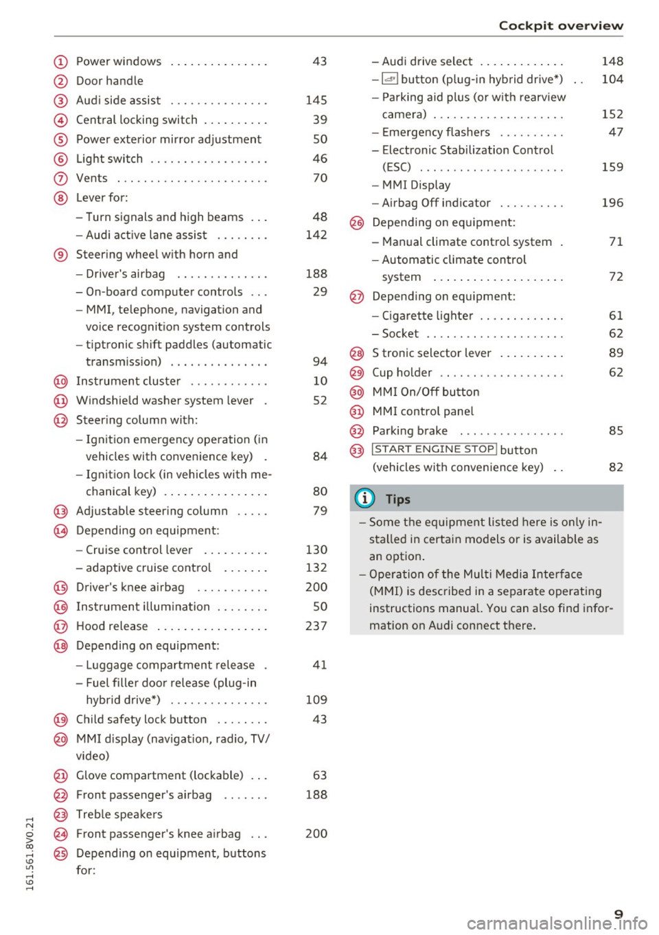
Power windows
Door handle
Aud i side assist ............ .. .
Central locking switch .. ... .. .. .
Power exterior mirror ad justment
L ig ht swit ch ............... .. .
Vents
L ever fo r:
- Turn signals and high beams . . .
- Audi a ct ive lane assis t ..... .. .
® Steer ing whee l w ith horn and
- Drive r's airbag ...... ..... .. .
- On-board compute r controls .. .
- MMI, telephone, navigation and
vo ice recognit ion system cont rols
- tiptronic sh ift paddles (automatic
transm iss ion) . .. .... ... .. .. .
@ Ins trumen t cluste r ....... .. .. .
@ W indshield washer system lever .
@ Steering column with:
- Ignit ion emergency operation ( in
vehicles with convenience key) .
- Ignit io n lock (in vehicles wi th me -
chanical key) . .. ..... ... .. .. .
@ Adjustable steer ing column .. .. .
(B) D epending on equipment:
- Cruise control leve r ..... .. .. .
- adaptive cruise contro l .. .. .. .
@ Driver's knee a irbag ........ .. .
@ Ins trumen t illum ination ..... .. .
@ Hood release ... .. .... ... .. .. .
@ Depending on equipment: 43
145 39
so
46 70
48
142
188 29
94
1 0
52
84
80
79
130
132
200
so
237
- Luggage compartment release . 41
- Fuel fille r doo r release (plug-in
hybrid drive*) . . . . . . . . . . . . . . . 109
@ Child safety lock button . . . . . . . . 43
@ MMI d isp lay (nav igat ion, radio, TV/
v ideo)
@ Glove compartment (lockable) . . . 63
@ Front passenger 's airbag . . . . . . . 188
@ Treb le spe akers
@ Front passenger's knee a irbag . . . 200
@ Depending on equipment, b uttons
for:
Coc kpit o ve rv iew
- Aud i drive select . .. .. ..... .. .
- la •I bu tton (p lug-in hyb rid dr ive *)
- P ark ing aid plus (or w it h rearv iew
came ra) . .. .. .............. .
- E me rgency flashers ......... .
- Electronic Stabilization Control (ESC) ....... .. ............ .
- MMI Display
- Airbag Off indicator ......... .
@ Depend ing o n eq uipment:
- Manual climate control system
- Automatic climate con trol
system ..... .. ... .. ..... .. .
@ Depend ing o n equ ipment:
- Ciga ret te lighte r ............ .
- Soc ket .. .. .. .. ............ .
@ S tronic selector lever .. ..... .. .
@) Cup holder .. .. .. ............ .
@ MM I On/Off bu tton
@ MMI contro l pane l
@ Parking brake . .. ............ .
@ I STAR T ENGINE ST OP ! button
(vehicle s with conve nience key)
(1) Tips
- Some t he e quipment listed here is o nly in
sta lled in certai n mo del s or is available as
an opt ion . 148
10
4
152
47
159
196
71
72
61
62
8 9
62
85
82
- Ope ra tio n of the Mul ti M edia Inte rface
(M MI) is described in a separate operatin g
instructions manual. Yo u can also fi nd info r
mation on A udi connect t here .
9
Page 12 of 328
Instrumen ts and ind icator ligh ts
Instruments and indicator Lights
Instruments
Instrument cluster overview
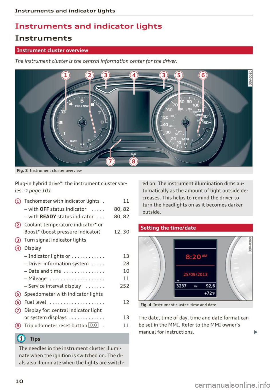
The instrument cluster is the central information center for the driver.
Fig. 3 Instrument cluster overv iew
Plug-in hybrid drive*: the instrument cluster var
ies:
~ page 101
CD Tachometer with indicator lights
- with
OFF status ind icator .... .
- with
READ Y status indicator .. .
@ Coolant temperatu re indicato r* or
Boost* (boost pressure ind icator)
@ Turn signal indicator lights
@ Display 11
80,82
80,82
1 2,30
- Indicator lights or . . . . . . . . . . . . 13
- Drive r informat ion system . . . . . 28
- Date and time . . . . . . . . . . . . . . . 10
- Mileage . . . . . . . . . . . . . . . . . . . . 11
- Service interva l display . . . . . . . 252
® Speedome ter w ith ind icator lights
® Fuel level ...... ........... .. .
0 D isp lay for : centra l indicator light
or system displays ............ .
@ Trip odometer reset button 10.01
{D) Tips
12
13
11
The needles in the instrume nt cluster ill umi
nate when the ign ition is swi tched o n. The di
als a lso illuminate when the lights are switch-
10
ed on. The instrument illumination dims au
tomatica lly as the amount of light outside de
creases. This helps to rem ind t he driver to
turn the head lights on as it becomes dar ker
outside.
Setting the time/date
Fig. 4 Instrument cluster : time and date
The date, time of day, time and date format can
be set in the MMI. Refer to the MMI owner's
manua l for instructions.
i 0 > a) m
Page 19 of 328
,....,
N
0 > co ,....,
o r
o r
fi. D
&
/:
(j)
or H
eadlig ht ra nge contro l system*
c::> poge25
Adapt ive light*
c::> page 25
Light/rain sensor*
c::> page 2 5
Active lane ass ist*
c::> page 143
Transmission
c::> page 95
e-tron: system warning*
c::>page 101
e-tron: charging system *
c::> page 121
e -t ron: dr iving power *
c::> page 101, c::> page 109
e-tron: vehicle sound *
c::> page 101
Instruments and ind icator lights
or
Ad Blue/
&
AdB lue malfunction *
c::> page 234
Other indicator lights
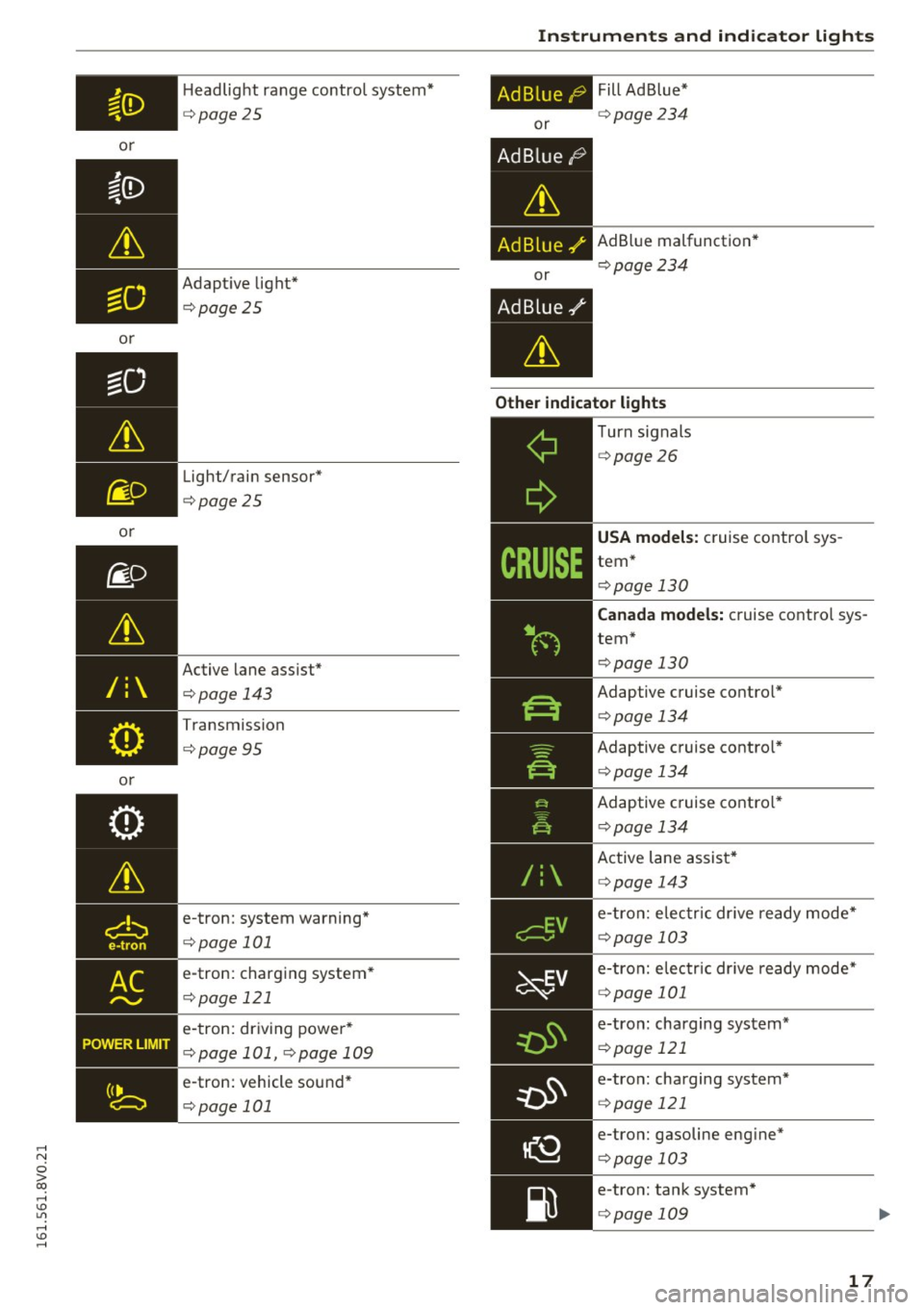
--------------Turn signals
c::> page 26
USA models: cruise contro l sys
tem *
c::> page 130
Canada models: cruise contro l sys
tem *
c::> page 130
Adaptive c ruise contro l*
c::> page 13 4
Adaptive c ruise contro l*
c::> page 13 4
Adaptive c ruise contro l*
c::> page 134
Active lane assist *
c::> page 143
e -tr on: e lec tric dr ive re ady mode *
c::> page 103
e-tron: e lec tric dr ive ready mode*
c::> page 101
e-tron: charg ing sys tem*
c::> page 121
e-tron: charging system *
c::> page 121
e-tron: gasoline eng ine*
c::> page 103
e-tron: tan k system*
c::> page 109
17
Page 28 of 328
Instrumen ts and ind icator ligh ts
still control all wiper functions that are
independent of the rain sensor.
Drive to an a uthorized Aud i dea ler or authorized
Aud i Serv ice Facility immediately to have the
malfunction corrected .
; Adaptive dampers
Applies to vehicles: with Audi drive select
R Suspen sion : sys tem f ault!
There is an adaptive damper ma lf u nction.
Drive to an authorized Aud i dealer or authorized
Aud i Serv ice Facility immediately to have the
malfunct io n corrected.
¢¢ Turn signals
I f the . or
DI indicator ligh t bl inks, a turn s ig
na l is turned on. If both i ndicator lights are blink
i n g, the emergency flashers are on .
I n an indicato r light blinks twice as fast as usua l
then a blinker bulb has failed. Care fully drive to
an author ized Audi dealer or authorized Audi
Serv ice Facility immediately to have the malfunc
tion corrected.
(D Tips
For more information on the turn signals, re
fe r to~
page 48.
On-Board Diagnostic
system (OBD)
System indicator light (MIL)
The system indicator light (M IL)
¢4 in the instru
ment cluster is part of the On Board Diagnostic
System (080 II).
The warning/indicator light turns on when the ig nition is switched on and turns off once the en
gine is started and is running in id le at a stable
speed. This indicates that the MIL is functioning
correctly.
If the light doe s not turn off after starting th e
engine or turns on whi le driving, this may indi
cate there is a malfunct ion in the engine. If the
26
indicator tu rns on, the cata lytic conve rter may be
damaged.
D rive with reduced engine performan ce (avoid
high speeds for extended per iods of t ime and/o r
fast acceleration) and have the ma lfunction cor
rected. See an authorized Audi dealer or author
i zed Audi Service Facility .
The ind icator may turn on if the e lectro nic speed
li miter is faulty . For add itiona l information, refer
to
c::> page 130, Electronic speed limiter.
The MIL may a lso turn on if the fuel filler cap is
not clo sed corre ctly
c::> page 230.
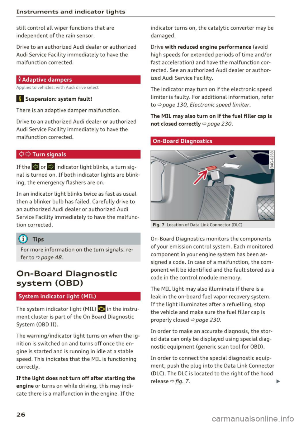
On-Board Diagnostics
F ig. 7 Locat ion of Data Link Connector (DLC)
On-Board Diagnostics mon itors the components
of your emission con trol system. Each monitored
component in your engine system has been as
s igned a code . In case o f a malfunction, the com
ponent will be identified and the fault stored as a
code in the contro l module memory.
The M IL light m ay also illum inate if there is a
l eak in the on -boa rd fuel vapor recovery sys tem .
If the light illuminates after a refuelling, stop
the veh icle and make sure the fuel filler cap is
properly closed
c::> page 230.
In orde r to make an accu rate diagnosis, the s to r
ed data can only be d isplayed using special d iag
nostic equipment (generic scan tool for 080) .
In orde r to co nnect the special d iagnost ic equ ip
ment, push the plug into the Data Link Connector
(DLC). The DLC is located to the r ight of the hood
release
c::> fig. 7. II>
Page 38 of 328
Opening and clo sin g
only the driver 's door or the entire vehicle should
un lock when unlocking
r::!;> page 39 .
Automatic locking (Auto Lock )
The Auto Lock function locks all doors and the
luggage compartment lid once the speed has
ex
ceeded approx imately 9 mph (15 km/h).
The car is unlocked again once the ign ition key is
removed. In addition, the vehicle can be u nlocked
if the opening function in the power locki ng sys
tem sw itch is used or one of the door handles is
pulled .
I n the event of a crash with a irbag deployment ,
the doors automat ica lly unlock to allow access to
the vehicle.
Ant i-theft alarm s yst em *
If t he ant i-theft alarm system detects a veh icle
break-in, audio and v isual warning signals are
tr iggered .
The ant i- theft alarm system turns on automati
cally when you lock the vehicle .
It deactivates
when unlocking using the remote control key or
by touc hing the sensor on the door handle (con
ven ience key).
To sw itch the ala rm off, press the@ button o n
the remote control key or convenience key or
sw itch the ignition on. The a la rm also stops auto
mat ica lly after a certain amount of time.
Tu rn sign als
The turn s ignals flash tw ice when you unlock the
vehicle and flash once when you lock the vehicle .
If they do not f lash, one of the doors, the lug
gage compartment lid or the hood is not locked
or the ignition is still sw itched on (the latter ap
plies to veh icles with a convenience key) .
Unintentionally loc king your se lf out
The fo llowing conditions prevent you from lock
ing your remote control key in the vehicle :
- The vehicle does not lock with the central lock
ing switch if the driver 's door is op en
r::!;> page 39.
-On vehicles with a convenience key* , the lug
gage compartment lid un locks again after clos-
36
ing if the most recent ly used key is in the lug
gage compartment.
To avo id accidentally locking yourself out, do not
l ock your vehicle with the remote control key or
convenience key* until all doors and the luggage
compartment lid ar e closed.
{!) Tips
- Do not leave va luables unattended in the ve
hicle. A locked vehicle is not a safe!
- If the LED in the upper e dge of the drive r's
door turns on for about 30 seconds after
the vehicle is locked, there is a malfunction in the power locking or the anti-theft a larm
system *. Have the problem corrected by an
authorized Audi dealer or authorized Audi
Service Facility.
LED and batteries in the remote control key
Fig . 19 Remote con tro l key: LED
Fig . 20 Remote contro l key: o penin g the cover
LED in th e re mot e co nt rol k ey
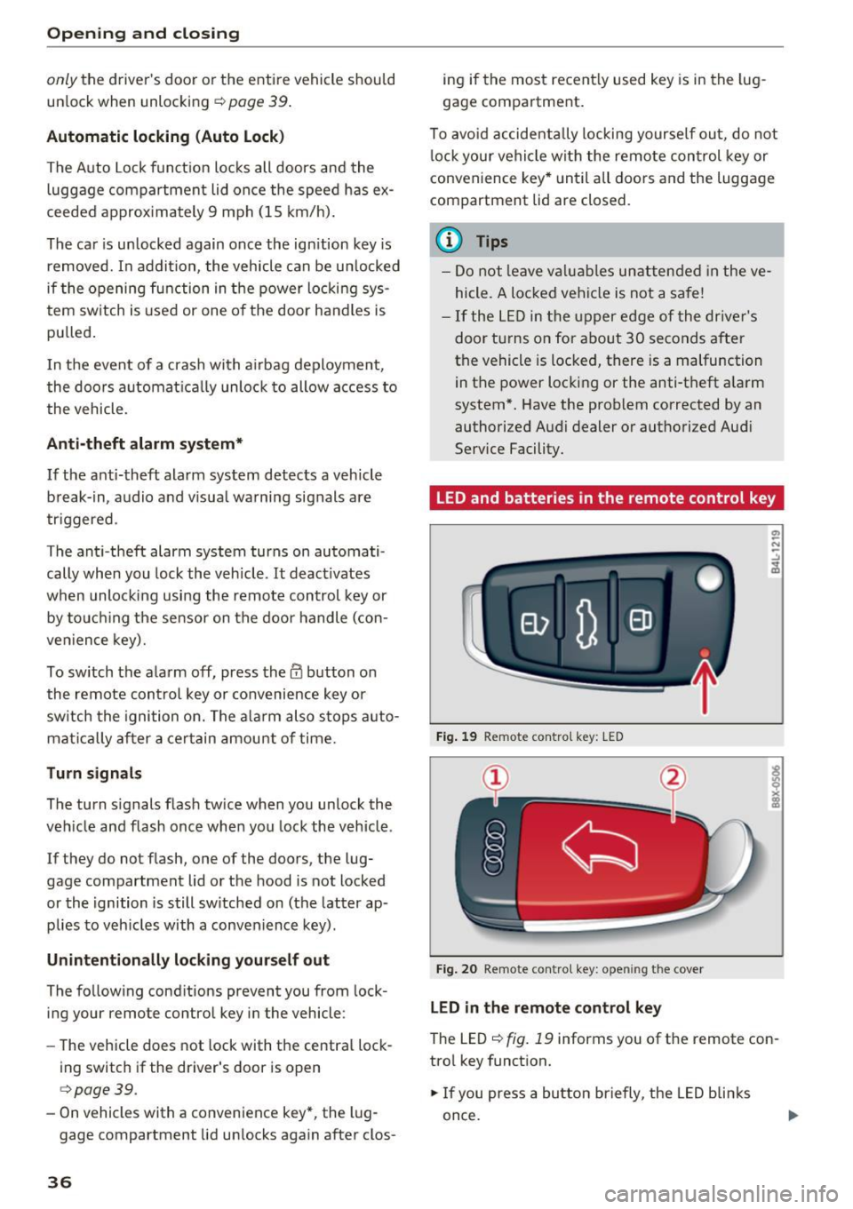
The LED r=> fig. 19 informs you of the remote con
trol key function.
.. If you press a button briefly , the LED blinks
once.
Page 49 of 328

.... N
0 > CX)
.... I.Cl U"I
.... I.Cl ....
When switched on, adaptive light adjusts to
curves depending on the vehicle speed and steering wheel angle. This provides better lighting
through the curve. The system operates in a
speed range from approximately 6 mph (10 km/
h) to 68 mph (110 km/h).
Static cornering light* (vehicles with adaptive
light) -the cornering light switches on automati
cally when the steering wheel is turned at acer
tain angle at speeds up to approximately 44 mph
(70 km/h) and when the turn signal is activated
at speeds up to approximately 25 mph (40 km/
h). The area to the side of the vehicle is illuminat
ed better when turning.
Speed dependent light distribution* -The speed
dependent light distribution adapts the light in
towns and on highways or expressways . Intersec
tions can also be illuminated on vehicles with a
navigation system* .
Highway light function*
(Vehicles with adaptive light or LED headlights) -
This function adapts the lighting for highway
driving based on vehicle speed .
& WARNING
-Automatic headlights* are only intended to
assist the driver. They do not relieve the
driver of responsibility to check the head
lights and to turn them on manually accord
ing to the current light and visibility condi
tions. For example, fog cannot be detected by the light sensors . So always switch on the
low beam under these weather conditions
and when driving in the dark
io.
-Accidents could occur if you cannot see the
road ahead of you well and if others on the
road cannot see you . Always switch your
headlightsonsothatyoucanseetheroad
ahead of you and others can see your vehicle
from behind.
- The rear fog lights should only be turned on
in accordance with traffic regulations, to
prevent glare for traffic behind your vehicle .
-If the battery has been discharging for a
while, the parking lights may switch off au
tomatically to conserve the battery charge
Lights and Vision
for the next time the engine is started. Al·
ways make sure your vehicle complies with
legal regulations regarding sufficient and
safe lighting when parking it. Avoid using
the parking lights for several hours.
- Please observe legal regulations when using
the lighting systems described .
@ Tips
-The light sensor for the automatic head
lights* is in the rearview mirror mount.
Therefore, do not place any stickers in this
area on the windshield.
- Some functions of the exterior lighting can
be adjusted
¢ page 48 .
-If you turn off the ignition while the exterior
lights are on and open the door, you will
hear a warning tone.
- In some market-specific versions, the tail
lights do not turn on when switching on the
daytime running lights .
- In cool or damp weather, the inside of the
headlights, turn signals and tail lights can
fog over due to the temperature difference
between the inside and outside. They will
clear shortly after switching them on. This
does not affect the service life of the light
ing.
- A message will appear in the instrument
cluster if there is a malfunction in the light
sensor
¢ page 25.
Emergency flasher
Fig. 33 Inst rume nt panel: e merge ncy flasher butto n
The emergency flashers makes other drivers
aware of your vehicle in dangerous situations .
N Cl) M 0
> Cl) (0
47
Page 50 of 328

Lights and Vision
.,. Press the~ button to switch the emergency
flashers on or off.
You can indicate a lane change or a turn whe n the
emergency f lashers are sw itched on by using the
turn signal lever. The emergency flashers stop
temporarily .
The emergency flashers also work when the igni
tion is turned off.
(0, Tips
You s hou ld sw itch the emergency flashers on
if:
- You are the last car in a traff ic jam so that
a ll other vehicles appro ach ing from be hind
can see yo u, or if
- You r vehicle has bro ke n down or you are
having an eme rgency, or if
- Y our vehicle is being towed or if you a re
tow ing another vehicle .
Turn signal and high beam lever
The lever operates the turn signals, the high
beams and the headlight fla sher.
F ig. 34 Turn signal and h igh bea m lever
Tu rn signal s¢¢
N
0
.... 9 ::i:
;ii
The turn signals activate when you move the lev
er into a turn signal position when the ignition is
sw itched on.
(D -Turn signal
@ -Turn signal
The turn signal blinks three times if you tap the
lever (conven ience turn s ignal).
48
High beams and headlight flasher [D
Move the lever to the corresponding position:
@ -high beams on
@-high beams off or headlight flasher
The
II i ndicator light in the instrument cl uster
turns on.
A WARNING
High beams can cause glare for other drivers,
which increases the risk of an accident. For
this reason, only use the high beams or the
headlight flasher when they will not create
gla re for othe r drive rs .
Adjusting the exterior lighting
The settings are adjusted in the MMI.
.,. Select : the I MENU I button > Car > Systems *
control button > Vehicle settings > Exte rior
light ing .
Automatic headlights
Yo u can adjust the following settings in the Au
tomati c headlights
menu:
Activation time -you can ad ju st if the headlights
swi tch on
Early , Medium or Late acco rd ing to t he
sensi tivity of the light sensor.
Audi adaptive light * -you can sw itch adaptive
li gh t
On an d Off .
Coming home, Leaving home*
The coming home f unction illuminates the area
outside the vehicle when you turn the ignition off
and open the driver 's door . To turn the function
o n, select
Lights when leaving car > On .
The leaving home illum inates the area outside
the ve hicle when you unlock the vehicle . To turn
the function on, se lec t
Lights when unlocking
car > On .
The coming home and leav ing home functions
o nl y operate when it is dark and the light sw itch
i s in the
AUTO pos ition . ..,.
Page 87 of 328
.... N
0 > CX)
rl I.Cl U"I
rl I.Cl ....
This message appears and a warning tone sounds if you open the driver's door when the ignition is
switched on. Switch the ign ition off so that the
battery will not d ischarge.
Pressing start/stop button again will switch off
engine!
This message appears when you press the
ISTART ENGINE STOPI* button while driving
¢ page 83, Emergency off function.
Engine start system malfunction. Please con
tact Service
The engine automatic start system has a mal
function . Drive to an author ized Audi dealer or
author ized Audi Service Facility immediate ly to
have the malf uncti on corrected. To start the en
g ine, press and hold the
!START ENGINE STOPI
button.
DJ Key not recognized. See owner's manual
This message appears if there is no convenience
key inside the vehicle or if the system does not
recognize the key. The conven ience key may not
be recognized, for example, if it is covered by an
object that
disrupts the signal (such as a brief
case), o r if the key battery is weak. Electronic de
vices such as cell phones can also interfere with
the signal.
To still be able to start or stop the engine, refer
to "Cor rect ing a malfunction" ¢
page 84.
Ill Key not in vehicle?
The Ill indicator light turns on and this message
appears if the convenience key was removed from
the vehicle when the eng ine was running . If the
conven ience key is no longer in the vehicle, you
cannot switch the ignition on o r start the engine
once yo u stop it. In addition, you cannot lock the
ve hicl e from the outside .
Press brake pedal
This message appears if you do not press the
brake pedal when starting the eng ine .
Please engage N or P
This message appears when starting or s topping
the engine if the selector lever is not in the Nor P
position . The engine will not start/stop .
Driving
Shift to P, vehicle can roll away . Doors can only
be locked in P
T his message appears for safety reasons along
with a warning tone. It appears if the selec to r
lever for the automat ic transmission is not in the
P position when switching the ignition off with
the
I START ENGINE STOPI * button. Shift these
lector lever to the P position. Otherwise, the vehi
cle could roll. You also cannot lock the vehicle us
ing the locking sensor o n the door hand le or us
ing the conven ience key.
Electromechanical
parking brake
Operating
The electromechanical parking brake replaces
the hand brake.
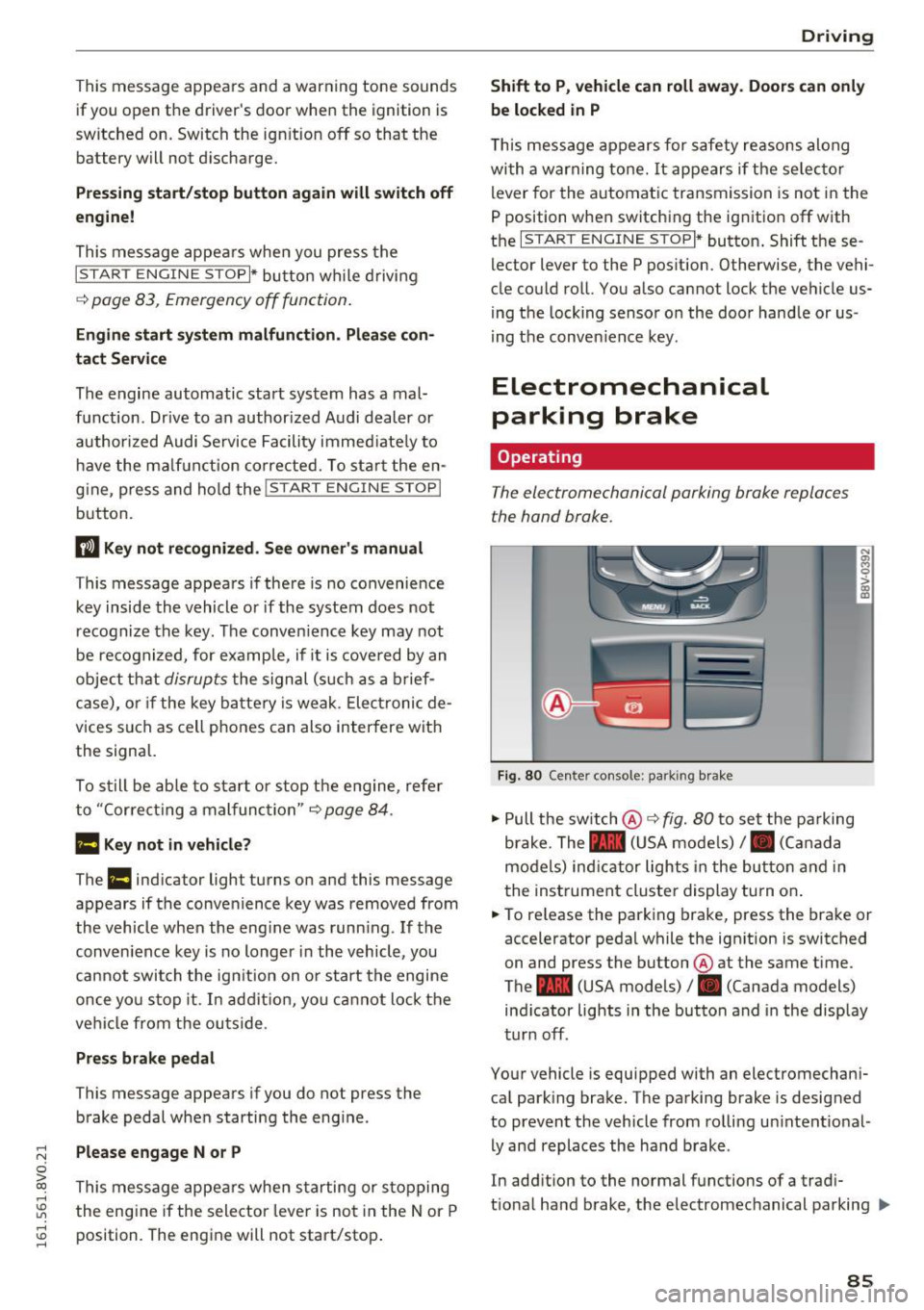
Fig . 80 Center console : pa rk ing brake
" Pull the switch @¢ fig. 80 to set the parking
brake. The - (USA models),. (Canada
models) ind icator lights in the button and in
the instrument cluster display turn on .
" To release the parking brake, press the brake or
accelerator pedal while the ign ition is switched
on and press the button @at the same time.
The - (USA models), . (Canada models)
ind icator lights in the button and in the display
turn off.
Your vehicle is equipped with an electromechani
cal park ing brake. The parking brake is designed
to prevent the vehicle from rolling un intent io nal
ly and replaces the hand brake .
In addition to the normal functions of a tradi
t ional hand brake, the electromec hanical parking ..,.
85
Page 147 of 328

.... N
0 > CX)
.... I.Cl U"I
.... I.Cl ....
Late: in this set ting, t he system provides correc
tive steering just before a vehicle whee l touches a
detected lane marker line.
Vibrat ion warning
You can switch the additional vibrating warning
i n the steering wheel on or
off.
& WARNING
With the vibration warning switched off, no
visible warning will appear in the instr ument
cluster display when crossing a lane marker.
@ Tips
Market-specific: your sett ings are stored au
tomatically and assigned to the remote con
trol key in use.
Audi side assist
Description
A pp lies to vehicles: with Audi side assist
Fig. 130 Sensor detectio n range
Fig. 131 D isplay on the exterior mirro r
Side assist he lps you monitor your blind spot and
traffic behind your vehicle. Within the limits of
the system, it warns you about vehicles that are
com ing closer or that are traveling with yo u with-
A ss ist
in senso r range (D ¢ fig. 130 : if a lane change is
classified as critical, the display @ in the exterior
mirror¢
fig. 131 turns on .
T he displ ay in the left exterior mirror p rovides as
sistance when making a lane change to the le ft,
whi le the display in the right exterior mirror pro
vides ass istance when making a lane ch ange to
the right.
Information stag e
As long as you do not a ct ivate the tu rn signal,
side assist
informs you about vehicles that are
detected and classified as critical. The display in
the mirror turns on, but is dim .
T he disp lay remains dim i n the information stage
so that your view toward the front is not distur
bed.
Warning stage
If you activate the turn s ignal, side assist warns
yo u about vehicles that are detected and classi
fied as crit ica l. T he d isp lay in the respective mir
ror blinks bright ly. If this happens, check traffic
by glancing in the rearview mirror and over your
shou lder ¢.&.
in General information on
page 146.
(D Tips
- You can adjust the brightness on of the dis
play on the rearview mirror¢
page 147.
145
Page 158 of 328
Parking systems
Parallel parking
Applies to veh icles: w ith pa rk ing system p lus with rearv iew
camera
This view may be used when parallel parking
along the side of a street.
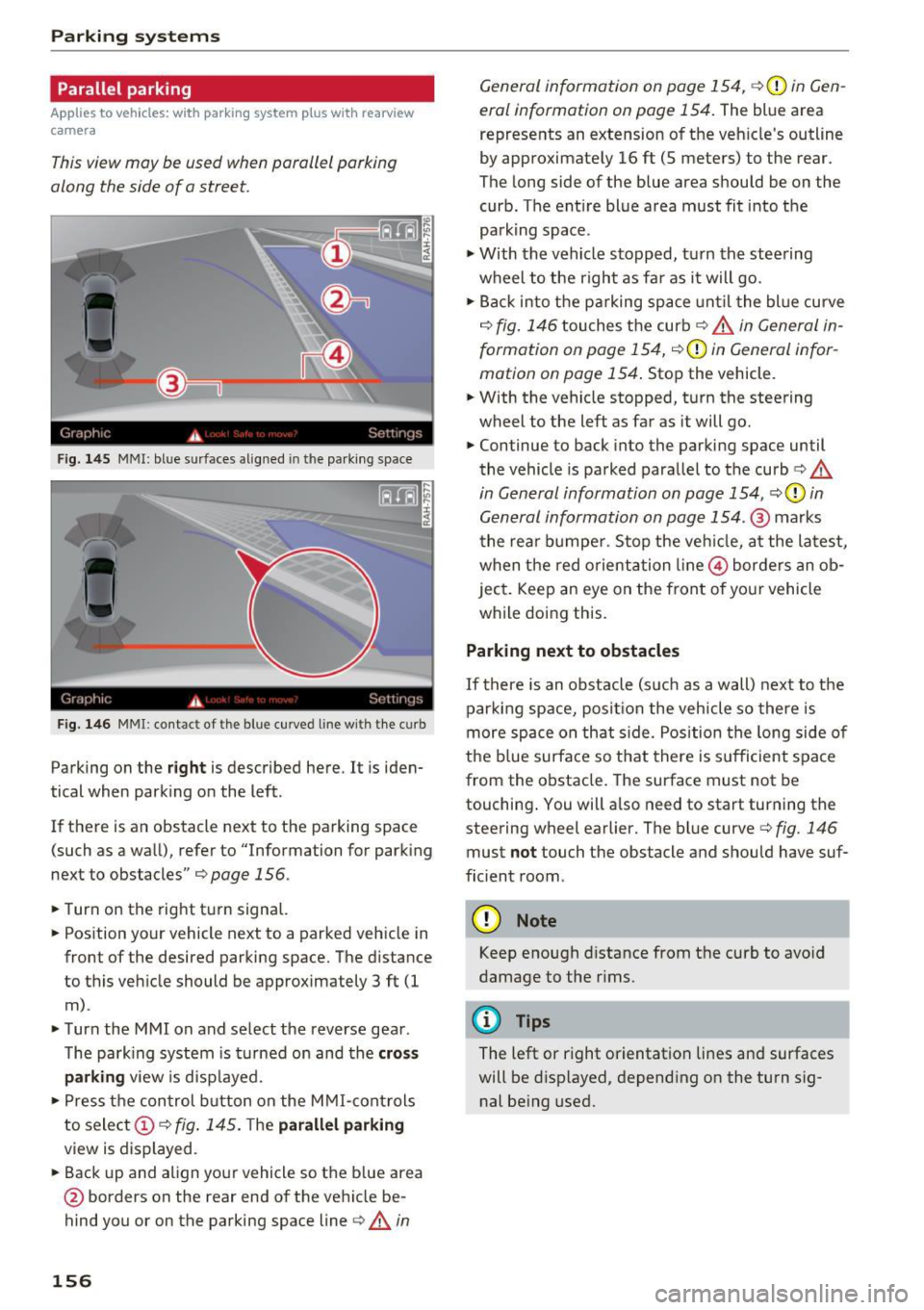
Fig. 145 MMI: bl ue s urfaces aligned in the parki ng space
Fig. 146 MMI: contact of the blue curved l ine w ith the curb
Parking on the right is described here . It is iden
tical when park ing on the left .
If there is an obstacle next to the parking space
(such as a wall), refer to "Information for park ing
next to obstacles"
c:.> page 156 .
.,. Turn on the right turn signal.
.,. Position your vehicle next to a parked vehicle in
front of the desired parking space. The distance
to this veh icle should be approximately 3 ft (1
m) .
.,. Turn the MMI on and select the reverse gear .
The park ing system is turned on and the
cross
parking view is d ispla yed.
.,. Press the control button on the MMI-controls
to select
(D c:.> fig. 145. T he parallel parking
view is displayed .
.,. Back up and align your vehicle so the blue area
@ borders on the rear end of the vehicle be
hind you or on the parking space line
c:.> A in
156
General information on page 154, c:.> (D in Gen
eral information on page 154.
The blue area
represents an extension of the veh icle's outline
by approximately 16 ft (5 meters) to the rear.
The long side of the blue area shou ld be on the
curb. The ent ire blue area must fit into the
parking space .
.,. With the vehicle stopped, t urn the steering
wheel to the right as far as it will go .
.,. Bac k into the pa rking space unt il t he blue curve
c:.> fig. 146 touches the curb c:.> A in General in
formation on page 154,
c:.>(D in General infor
mation on page 154.
Stop the vehicle .
.,. With the vehicle stopped, turn the steering
wheel to the left as far as it will go .
.,. Continue to back into the parking space until
the vehicle is parked parallel to the curb
c:> A
in General information on page 154, c:.>(D in
General information on page 154 .@
marks
the rear bumper . Stop the vehicle, at the latest,
when the red orientation line@) borders an ob
ject . Keep an eye on the front of your vehicle
while doing this.
Parking next to obstacles
If there is an obstacle (such as a wall) next to the
parking space, position the vehicle so there is
more space on that side. Position the long side of
the b lue surface so that there is sufficient space
from the obstacle. The surface must not be
touching . You will a lso need to start turning the
steering wheel earlier. The blue curve
c:.> fig. 146
must not touch the obstacle and should have suf
ficient room .
(D Note
Keep enough distance from the curb to avo id
damage to the rims.
¢j) Tips
The left or right orientation lines and surfaces
will be d isp layed, depending on the turn s ig
nal being used.