check engine AUDI A3 2020 Owner´s Manual
[x] Cancel search | Manufacturer: AUDI, Model Year: 2020, Model line: A3, Model: AUDI A3 2020Pages: 400, PDF Size: 107.47 MB
Page 316 of 400
Checking and Filling
Message
EG / @ Brakes: stop vehicle and check brake
fluid level
Stop the vehicle and check the brake fluid level.
See an authorized Audi dealer or authorized Audi
Service Facility for assistance.
Changing the brake fluid
Brake fluid should be changed at regular inter-
vals. Have the brake fluid changed by an author-
ized Audi dealer or authorized Audi Service Facili-
ty. The authorized Audi dealer or authorized Audi
Service Facility will inform you of the replace-
ment intervals.
Z\ WARNING
— If the brake fluid level is below the MIN
marking, it can impair the braking effect and
driving safety, which increase the risk of an
accident. Do not continue driving. See an au-
thorized Audi dealer or authorized Audi
Service Facility for assistance.
— If the brake fluid is old, bubbles may form in
the brake system during heavy braking. This
could impair braking performance and driv-
ing safety, which increases the risk of an ac-
cident.
— The brake fluid in your vehicle must meet
the standard VW 501 14 and is available at
an authorized Audi dealer or authorized
Audi Service Facility. If this brake fluid is not
available, another high-grade brake fluid of
equivalent quality may be used, and it must
meet the U.S. Federal Motor Vehicle Stand-
ard (FMVSS) 116 DOT 4, Class 6.
© Note
— If the brake fluid level is above the MAX
marking, brake fluid may leak out over the
edge of the reservoir and result in damage
to the vehicle.
— Do not allow any brake fluid to come into
contact with the vehicle paint, because it
will corrode the paint.
314
Electrical system
If the | or = indicator light turns on, there is a
malfunction in the generator, the battery, or the
vehicle electrical system.
z= Electrical system: malfunction! Battery is
not charging
Safely stop your vehicle, do not continue driving
and switch the ignition off > A\. See an author-
ized Audi dealer or authorized Audi Service Facili-
ty for assistance.
=} Electrical system: malfunction! Restart not
possible. Please contact Service
It will not be possible to restart the engine once
you turn it off. Vehicle functions/driving stability
may be limited. Drive to an authorized Audi deal-
er or authorized Audi Service Facility immediate-
ly.
z= Electrical system: malfunction! Please con-
tact Service
Switch off all electrical equipment that is not
needed. Vehicle functions/driving stability may
be limited. Drive to an authorized Audi dealer or
authorized Audi Service Facility immediately.
= Electrical system: low battery charge. Bat-
tery will be charged while driving
The starting ability may be impaired.
If this message turns off after a little while, the
vehicle battery has charged enough while driving.
If this message does not turn off, drive immedi-
ately to an authorized Audi dealer or authorized
Audi Service Facility.
ZA\ WARNING
When there is an electrical system malfunc-
tion, vehicle functions may not work and driv-
ing stability may be limited, which increases
the risk of an accident. Do not continue driv-
ing and switch the ignition off. See an author-
ized Audi dealer or authorized Audi Service Fa-
cility for assistance.
Page 317 of 400

8V2012721BK
Checking and Filling
Battery
eae mee eles)
Because of the complex power supply, all work on
batteries such as disconnecting, replacing, etc.,
should only be performed by an authorized Audi
dealer or authorized Audi Service Facility > A\.
Multiple batteries with different technologies
may be installed in your vehicle:
— Vehicle battery (for example, for starting the
engine, basic power supply) > page 315, Lead
battery or > page 316, Other battery types
— Auxiliary battery (for example, for recuperation
or optional equipment) > page 316, Other bat-
tery types
— Applies to: plug-in hybrid drive: High-voltage
battery (for example, for electric driving)
=> page 96.
Not running the vehicle for long periods of
time
The battery will gradually drain if the vehicle
does not run for long periods of time. To ensure
that the vehicle can still be started, the electrical
equipment will be reduced or switched off
=> page 82. Some convenience functions, such as
interior lighting or power seat adjustment, may
not be available under certain circumstances.
These convenience functions will be available
again once you switch the ignition on and start
the
engine.
Even when electrical equipment is switched off,
the equipment can still drain the battery if the
vehicle is not driven for long periods of time.
Deep draining results in a chemical reaction that
destroys the inside of the battery. The battery
must be charged every month to prevent this
= page 316. Contact an authorized Audi dealer or
authorized Audi Service Facility for more infor-
mation.
Winter operation
Cold weather places higher demands on the bat-
tery. This results in reduced starting ability. Have
the battery checked by an authorized Audi dealer
or authorized Audi Service Facility before cold
weather begins.
ZA WARNING
— All work on the battery or electrical system
in your vehicle can result in injuries, chemi-
cal burns, accidents, or burns. Because of
this, all work must be performed only by an
authorized Audi dealer or authorized Audi
Service Facility.
— Never connect the charging cable or jump
start cable directly to your vehicle battery.
Only use the connections in the engine com-
partment > page 316.
Z\ WARNING
California Proposition 65 Warning:
— Battery posts, terminals and related acces-
sories contain lead and lead compounds,
chemicals known to the State of California
to cause cancer and reproductive problems.
Wash hands after handling.
@) Note
If the vehicle will be parked for long periods
of time, protect the battery against the cold
so that it will not be destroyed by “freezing”
= page 316, Charging the battery.
Lead battery
Explanation of warnings:
© Always wear eye protection.
Battery acid is highly corrosive. Always
wear protective gloves and eye protection.
® Fire, sparks, open flame, and smoking are
@/
aa
forbidden.
A highly explosive mixture of gases can
VN form when charging batteries.
Always keep children away from battery
®) acid and the battery.
Always follow the instructions in the oper-
ating manual.
@) For the sake of the environment
¥ Lead-acid batteries must be disposed of
using methods that will not harm the
315
Page 318 of 400

Checking and Filling
environment. Do not dispose of them in
household trash. They contain harmful sub-
stances, such as sulfuric acid and lead, and al-
so recyclable raw materials. Contact an au-
thorized Audi dealer or authorized Audi Serv-
ice Facility for more information.
Other battery types
Explanation of warnings:
Fire, sparks, open flame, and smoking are
eS) forbidden.
Always keep children away from battery
@) acid and the battery.
@/ | Always follow the instructions in the oper-
fQ | ating manual.
ZA\ WARNING
All work on the batteries must only be per-
formed by an authorized Audi dealer or au-
thorized Audi Service Facility.
— Gases that escape from these different bat-
tery types can be poisonous or flammable.
— The contents of these battery types can be
corrosive. If any battery contents come into
contact with the skin, flush the affected
area for at least 15 minutes with clean wa-
ter. Then wash the affected area with soap.
Have the affected area examined by a medi-
cal professional.
@ Note
Components must not be connected to the
battery terminals and wires on these battery
types because this increases the risk of dam-
age, for example due to overvoltage.
@ For the sake of the environment
<2 These types of batteries must be dis-
posed of using methods that will not harm
the environment. Do not dispose of them in
household trash. They contain harmful sub-
stances and recyclable raw materials. Contact
an authorized Audi dealer or authorized Audi
Service Facility for more information.
316
Charging the battery
Applies to: vehicles with vehicle battery in the engine com-
partment
Fig. 254 Engine compartment: connections for charger or
jump start cable
B8V-0529
Applies to: vehicles with jump start point (+)
Fig. 255 Engine compartment: connections for charger or
jump start cable
Note the safety precautions > page 304, General
information, > /\ in Battery general informa-
tion on page 315 and > /\.
Plug-in hybrid drive: > page 365.
Requirement: only use chargers with a maximum
charging current of 14.8 volts. The battery ca-
bles remain connected.
Depending on the engine, the battery is located
in the engine compartment or in the luggage
compartment. For vehicles with the battery in
the luggage compartment, a jump start point
that is also used for battery charging is located in
the engine compartment. The battery is always
charged in the engine compartment. The ground
point ©) is always located on the vehicle body.
> Switch off the ignition and all electrical equip-
ment.
> Open the hood > page 305.
Page 319 of 400
8V2012721BK
Checking and Filling
» Applies to: vehicles with vehicle battery in the
engine compartment: Open the cover on the
positive terminal > fig. 254.
> Applies to: vehicles with jump start point (+):
Open the cover on the positive terminal
> fig. 255.
> Clamp the terminal clamps on the charger cor-
rectly onto the ground point ©) and the positive
terminal @).
> Insert the power cable for the charging device
into the socket and switch the device on.
> At the end of the charging process, switch the
charger off and pull the power cable out of the
socket.
> Remove the charging device terminal clamps.
> Applies to: vehicles with vehicle battery in the
engine compartment: Open the cover on the
positive terminal.
> Applies to: vehicles with jump start point (+):
Close the cover on the positive terminal.
> Close the hood > page 305.
ZA WARNING
— Applies to: vehicles with jump start connec-
tions in the engine compartment: The
charging cable must never be connected di-
rectly to the vehicle battery. Only use the
connections in the engine compartment
=> page 316.
— A highly explosive mixture of gases can form
when charging batteries. Only charge the
battery in well-ventilated areas.
— A drained battery can freeze at tempera-
tures around 32 °F (0 °C). Do not charge or
use a frozen or thawed battery. If ice forms,
the battery housing can crack and battery
electrolyte can leak out, which increases the
risk of an explosion and chemical burns.
Contact an authorized Audi dealer or author-
ized Audi Service Facility for more informa-
tion.
— Do not connect or disconnect the charging
cable while charging because this increases
the risk of an explosion.
@) Tips
Read all of the manufacturer's instructions
for the charger before charging the battery.
Windshield washer
system
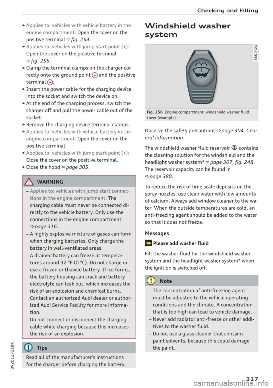
B8K-2123
Fig. 256 Engine compartment: windshield washer fluid
cover (example)
Observe the safety precautions > page 304, Gen-
eral information.
The windshield washer fluid reservoir & contains
the cleaning solution for the windshield and the
headlight washer system* > page 307, fig. 248.
The reservoir capacity can be found in
=> page 380.
To reduce the risk of lime scale deposits on the
spray nozzles, use clean water with low amounts
of calcium. Always add window cleaner to the wa-
ter. When the outside temperatures are cold, an
anti-freezing agent should be added to the water
so that it does not freeze.
Messages
gS Please add washer fluid
Fill the washer fluid for the windshield washer
system and the headlight washer system* when
the ignition is switched off.
@) Note
— The concentration of anti-freezing agent
must be adjusted to the vehicle operating
conditions and the climate. A concentration
that is too high can lead to vehicle damage.
— Never add radiator anti-freeze or other addi-
tives to the washer fluid.
— Do not use a glass cleaner that contains
paint solvents, because this could damage
the paint.
317
Page 320 of 400
Checking and Filling
Service interval display
The service interval display detects when your ve-
hicle is due for service.
The service interval display works in two stages:
— Inspection or oil change reminder: after driv-
ing a certain distance, a message appears in the
instrument cluster display each time the igni-
tion is switched on or off. The remaining dis-
tance or time is displayed briefly.
— Inspection or oil change due: if your vehicle
has reached an inspection or oil change interval
or both intervals at the same time, the mes-
sage Inspection due! or Oil change due! or Oil
change and inspection due! appears briefly af-
ter switching the ignition on/off.
Checking service intervals
You can check the remaining distance or time un-
til the next oil change or next inspection in the
Infotainment system. Select in the Infotainment
system: the [MENU] button > Vehicle > left con-
trol button > Service & checks > Service inter-
vals.
Resetting the indicator
An authorized Audi dealer or authorized Audi
Service Facility will reset the service interval dis-
play after performing service.
If you have changed the oil yourself, you must re-
set the oil change interval.
To reset the display, select in the Infotainment
system: the [MENU] button > Vehicle > left con-
trol button > Service & checks > Service intervals
> Reset oil change interval.
@ Note
— Only reset the oil change indicator if the oil
was changed.
— Following the service intervals is critical to
maintaining the function, service life, and
value of your vehicle, especially the engine.
Even if the mileage on the vehicle is low, do
not exceed the time for the next service.
318
Page 342 of 400

Wheels
the tread to separate and even cause the tire
to burst, increasing the risk of an accident.
— The tire pressure monitoring system does
not warn about damage or defects in the
tire construction that could cause the tire to
burst, for example. Inspect your tires regu-
larly.
Note that the tire pressure also depends on the
temperature of the tire. The tire pressure increas-
es as the engine becomes warmer while driving.
Z\ WARNING
Read and follow the important information
and notes > page 339.
@) Tips
— If tires are replaced, the sensors and valves
do not need to be removed or replaced. Only
replace the valve stem and, if necessary, the
valve and the wheel electronics. If you have
questions, see an authorized Audi dealer or
authorized Audi Service Facility.
— An incorrect display or a malfunction in the
tire pressure monitoring system can occur
after using the tire mobility kit. Have the
sensors replaced by an authorized Audi
dealer or authorized Audi Service Facility.
— For an explanation on conformity with the
FCC regulations in the United States and the
Industry Canada regulations, see
=> page 377.
Displaying tire pressures and temperatures
Applies to: vehicles with tire pressure monitoring system
Requirement: you must be driving the vehicle.
> Select in the Infotainment system: the [MENU
button > Vehicle > left control button > Service
& checks > Tire pressure monitoring > Display
tire pressure.
The current tire pressures are shown in green,
yellow or red numbers in the Infotainment sys-
tem:
— Green: the current tire pressure and the speci-
fied tire pressure are approximately the same.
— Yellow: the current tire pressure is lower than
the specified tire pressure.
— Red: the current tire pressure is much lower
than the specified tire pressure.
The specified tire pressure is the last tire pressure
that was stored > page 341.
340
@) Tips
The tire pressure or temperature is not dis-
played while the vehicle is stationary and in
adaptation mode. Dashes --.-- are shown in
place of the pressure and temperature.
ON ic deste oy
Applies to: vehicles with tire pressure monitoring system
If the @ indicator light turns on, the pressure in
at least one tire is too low or new sensors were
not adapted:
@ Indicator light turns on after turning the
ignition on
The tire pressure is too low compared to the
specified pressure.
> Check and store the tire pressure(s) the next
time it is possible > page 341.
@ Indicator light turns on while driving
Wheels with new sensors were not adapted or
the tire pressure has reached a critical level com-
pared to the specified pressure.
> Avoid unnecessary steering and braking maneu-
vers.
> Adapt your driving style to the situation.
> Stop as soon as possible and check the tire(s).
> If it is possible to continue driving, see an au-
thorized Audi dealer or authorized Audi Service
Facility immediately and have your tire(s) re-
paired or replaced.
ZA\ WARNING
Read and follow the important information
and notes > page 339.
Page 351 of 400

8V2012721BK
Emergency assistance
> Lift the cargo floor using the plastic handle @)
until the cargo floor engages behind the tabs
@ in both side panels > fig. 263 (upper image).
> Fold the cargo floor back before closing the
luggage compartment lid.
Vehicle tool kit and cargo floor cover
Applies to: vehicles with version 2
The vehicle tool kit, tire mobility kit* and com-
pressor* are stored in the luggage compartment
under the cargo floor cover @) > fig. 262.
> Engage the plastic hook () in the luggage com-
partment seal > fig. 263.
> Fold the cargo floor back before closing the
luggage compartment lid.
Z\ WARNING
Applies to: vehicles with jack
Improper use of the vehicle jack can cause se-
rious personal injuries.
— Never use the screw driver hex head to tight-
en wheel bolts, since the bolts cannot attain
the necessary tightening torque if you use
the
hex head, potentially causing an acci-
dent.
— The factory-supplied jack is intended only
for your vehicle model. Under no circum-
stances
should it be used to lift heavy
vehicles or other loads; you risk injuring
yourself.
— Never start the engine when the vehicle is
raised, which could cause an accident.
— Support the vehicle securely with appropri-
ate stands if work is to be performed under-
neath the vehicle; otherwise, there is a po-
tential risk for injury.
— Never use the jack supplied with your Audi
on another vehicle, particularly on a heavier
one. The jack is only suitable for use on the
vehicle it came with.
G) Tips
The vehicle jack* does not require any mainte-
nance.
Vehicle tool kit/tire mobility kit/
eyes
Applies to: vehicles with plug-in hybrid drive
0) Bb + 3
> i a
Fig. 264 Luggage compartment: side trim panel
The vehicle tool kit, tire mobility kit and the com-
pressor are located in the side trim panel @) and
in the luggage compartment.
G) Tips
The vehicle must not be operated without the
tire repair set.
Tire mobility kit
Applies to: vehicles with tire mobility kit
> Read and follow the important safety precau-
tions in > page 348.
> Set the parking brake.
> Move the selector lever into the "P" position.
> Check if a repair with the tire mobility kit is pos-
sible > page 349.
Using the tire mobility kit
Applies to: vehicles with tire mobility kit
B8K-1475
Fig. 265 Tire: tire damage that cannot be repaired
349
Page 354 of 400
Emergency assistance
Replacing wheels
Before changing a wheel
Observe the following precautions for your own
and your passenger's safety when changing a
wheel.
>» After you experience a tire failure, pull the car
well away from moving traffic and try to reach
level ground before you stop > A\.
> All passengers should leave the car and move
toa safe location (for instance, behind the
guardrail) > A\.
> Engage the parking brake to prevent your vehi-
cle from rolling unintentionally > A\.
> Move selector lever to position P > /\.
> If you are towing a trailer, unhitch the trailer
from your vehicle.
> Take the jack* > page 348 and the spare tire*
=> page 357 out of the luggage compartment.
ZA\ WARNING
You or your passengers could be injured while
changing a wheel if you do not follow these
safety precautions:
— If you have a flat tire, move a safe distance
off the road. Turn off the engine, turn the
emergency flashers on and use other warn-
ing devices to alert other motorists.
— Make sure that passengers wait in a safe
place away from the vehicle and well away
from the road and traffic.
—To help prevent the vehicle from moving
suddenly and possibly slipping off the jack*,
always fully set the parking brake and block
the front and back of the wheel diagonally
opposite the wheel being changed. When
one front wheel is lifted off the ground,
placing the Automatic Transmission in P
(Park) will not prevent the vehicle from mov-
ing.
— Before you change a wheel, be sure the
ground is level and firm. If necessary, use a
sturdy board under the jack”.
— Always store the vehicle tool kit, the jack*
and the replaced tire in the luggage com-
partment > page 60.
352
G) Tips
Obey all laws.
Changing a wheel
When you change a wheel, follow the sequence
described below step-by-step and in exactly that
order.
1. Remove the decorative wheel cover*. For
more details see also > page 353, Decorative
wheel covers or > page 353, Wheels with
wheel bolt caps.
2. Loosen the wheel bolts > page 353.
3. Locate the proper mounting point for the
jack* and align the jack* below that point
=> page 354.
4. Raise the car with the jack* > page 354.
Remove the wheel with the flat tire and then
install the spare > page 355.
6. Tighten all wheel bolts lightly.
Lower the vehicle with the jack*.
8. Use the wheel bolt wrench and firmly tighten
all wheel bolts > page 353.
9. Replace the decorative wheel cover*.
wn
=
ZA WARNING
Always read and follow all WARNINGS and in-
formation > A\ in Raising the vehicle on
page 355 and > page 356.
After changing a wheel
A wheel change is not complete without the do-
ing the following.
> Always store the vehicle tool kit, the jack* and
the replaced tire in the luggage compartment
=> page 60.
> Check the tire pressure on the spare wheel im-
mediately after mounting it.
> As soon as possible, have the tightening tor-
ques on all wheel bolts checked with a torque
wrench. The correct tightening torque is
90 ft lb (120 Nm).
> Have the flat tire replaced as soon as possible.
Page 362 of 400

Fuses and bulbs
Fuses and bulbs
Fuses
(ener aye mates
Fuse color identification
Fig. 280 Left side of the engine compartment: fuse cover
A fuse that has blown will have metal strips that
have burned through.
The fuses are located behind a cover in the steer-
ing column area > fig. 279 or under a cover on
the left side of the engine compartment
> fig. 280.
> Switch the ignition and all electrical equipment
off.
> Check the following table to see which fuse be-
longs to the equipment > page 361.
> Remove the cover.
> Remove the plastic clip from the fuse panel
cover in the engine compartment > fig. 280.
> Remove the fuse using the plastic clamp.
> Replace the blown fuse with a fuse that has the
same amp rating.
>» Reinsert the cover.
360
Color Current rating
in amps
Black a
Purple 3
Light brown 5
Brown 15
Red 10
Blue 15
Yellow 20
White or transparent [25
Green 30
Orange 40
5| | A\ WARNING
Do not repair fuses and never replace a blown
fuse with one that has a higher amp rating.
This can cause damage to the electrical sys-
tem and increases the risk of fire.
(!) Note
If a new fuse burns out again shortly after you
have installed it, have the electrical system
checked as soon as possible by an authorized
Audi dealer or authorized Audi Service Facili-
ty.
@ Tips
— The following table does not list fuse loca-
tions that are not used.
— Some of the equipment listed in the follow-
ing tables applies only to certain model ver-
sions or certain optional equipment.
Page 366 of 400
Emergency situations
Emergency situations
General
This chapter is intended for trained emergency
crews and working personnel who have the nec-
essary tools and equipment to perform these
operations.
Starting by pushing or
towing
@) Note
Vehicles with an automatic transmission can-
not be started by pushing or towing.
Jump starting
If needed, the engine can be jump started by an-
other vehicle battery.
Applies to: vehicles with plug-in hybrid drive: The
connection points for the jump start cable are
different > page 365.
If the engine does not start because the vehicle
battery is drained, you can jump start your vehi-
cle using another vehicle. Jump start cables are
needed to do this.
Both vehicle batteries must have 12 V nominal
voltage. The voltage capacity (Ah) of the vehicle
battery that is giving power must not be less
than the capacity of the drained vehicle battery.
Jump start cable
Only use a jump start cable with a large enough
diameter. Note the manufacturer's specifica-
tions.
Only use a jump start cable with insulated termi-
nal clamps.
Positive cable - usually red.
Negative cable - usually black.
A WARNING
— A drained battery can freeze at tempera-
tures around 32 °F (0 °C). If the vehicle bat-
364
tery is frozen, it must be thawed before con-
necting the jump start cables. If it is not,
the risk of an explosion and chemical burns
increases. After jump starting the vehicle,
drive to an authorized Audi dealer or author-
ized Audi Service Facility immediately to
have the vehicle battery checked.
— Read the warnings when working in the en-
gine compartment > page 304.
— Handling the jump start cables incorrectly
may cause the vehicle battery to explode
and lead to serious injuries.
— Applies to: vehicles with plug-in hybrid
drive: You must not give a jump start with
your vehicle. This could cause significant
damage to the electrical system in your ve-
hicle > page 365.
— Applies to: vehicles with the battery in the
engine compartment: To reduce the risk of
chemical burns, do not bend over the vehicle
battery.
@) Note
Jump start cables can cause considerable
damage to the vehicle electrical system if
they are connected incorrectly.
G@) Tips
— There must be no contact between the
vehicles, or else voltage could flow when
connecting the positive terminal and drain
the vehicle battery of the vehicle providing
the jump start.
— The drained vehicle battery must be con-
nected correctly to the electrical system.
— Switch off electrical equipment that is not
needed.