torque AUDI A3 2020 Owner´s Manual
[x] Cancel search | Manufacturer: AUDI, Model Year: 2020, Model line: A3, Model: AUDI A3 2020Pages: 400, PDF Size: 107.47 MB
Page 26 of 400
Instrument cluster
Boost indicator
Applies to: vehicles with Audi virtual cockpit: The
boost indicator is only displayed in the enhanced
view or in the sport view* > page 19.
The current engine load (meaning the current
boost pressure) is indicated by a bar.
Siam ele heels
Applies to: vehicles with shift light indicator
The
shift light indicator informs the driver when
the rpm limit is reached.
Accessing the shift light indicator
Requirement: tiptronic mode must be activated
=> page 76.
>» Select the sport view > page 19. The shift light
indicator is displayed with green, yellow and
red ranges in the upper areas of the tachome-
ter.
The shift light indicator will blink red when ap-
proaching the engine speed limit. Shift to the
next highest gear at the right time.
Sy Pam EN
Applies to: vehicles with Audi virtual cockpit and sport dis-
plays
Depending on the vehicle equipment, the sport
displays may include the G-meter, the engine da-
ta and the tire pressure monitoring system.
Accessing the sport displays
> Open the first vehicle functions tab using the
[<>] button on the multifunction steering
wheel.
> Select on the multifunction steering wheel: left
control button > Sport displays.
> Turn the left thumbwheel on the multifunction
steering wheel until the desired sport display
appears in the instrument cluster.
G meter*
The G meter displays the longitudinal and lateral
acceleration. The maximum values that are
reached are stored and displayed when the vehi-
cle is stationary.
24
> To reset the stored values, select on the multi-
function steering wheel: right control button >
Reset values.
Engine data*
The engine data displays the current power and
torque.
Tire Pressure Monitoring System*
The tire pressure monitoring system displays the
current tire pressures and temperature. Also see
=> page 339, Tire pressure monitoring system.
Page 95 of 400
8V2012721BK
Driving dynamic
ZA\ WARNING
Do not tow your vehicle if there is a malfunc-
tion in the electronic steering lock because
this increases the risk of an accident.
@) Tips
If the & or El indicator light only stays on
for a short time, then you may continue driv-
ing.
ALL wheel drive (quattro)
Applies to: vehicles with all wheel drive
The all-wheel drive system distributes the driving
power variably to the front and rear axle to im-
prove the driving characteristics. It works togeth-
er with selective wheel torque control, which can
activate when driving around curves > page 94.
The all-wheel drive system is designed for high
engine power. Your vehicle is exceptionally pow-
erful and has excellent driving characteristics
both under normal driving conditions and on
snow and ice. Always read and follow safety pre-
cautions > A\.
Z\ WARNING
— Even in vehicles with all wheel drive, you
should adapt your driving style to the cur-
rent road and traffic conditions to reduce
the risk of an accident.
— The braking ability of your vehicle is limited
to the traction of the wheels. In this way, it
is not different from a two wheel drive vehi-
cle. Do not drive too fast because this in-
creases the risk of an accident.
— Note that on wet streets, the front wheels
can “hydroplane’” if driving at speeds that
are too high. Unlike front wheel drive
vehicles, the engine RPM does not increase
suddenly when the vehicle begins hydro-
planing. Adapt your speed to the road condi-
tions to reduce the risk of an accident.
Electronic Stabilization
Control
Electronic Stabilization Control (ESC) supports
driver safety. It reduces the risk of slipping and
improves driving stability. ESC detects critical sit-
uations, such as if the vehicle is oversteering or
understeering, or if the wheels are spinning. The
brakes are applied or the engine torque is re-
duced in order to stabilize the vehicle.
If the I indicator light blinks while driving, the
ESC is actively regulating.
If the BB indicator light turns on, the system has
switched the ESC off. In this case, you can switch
the ignition off and then on to switch the ESC on
again. The indicator light turns off when the sys-
tem is fully functional.
If the BB indicator light turns on, ESC was limit-
ed or switched off manually > page 94.
The following systems are integrated in the ESC:
Anti-lock braking system (ABS)
ABS prevents the wheels from locking when brak-
ing. The vehicle can still be steered even during
hard braking. Apply steady pressure to the brake
pedal. Do not pump the pedal. A pulsing in the
brake pedal indicates that the system is acting to
stabilize the vehicle.
Brake assist
The brake assist system can decrease braking dis-
tance. It increases braking power when the driver
presses the brake pedal quickly in emergency sit-
uations. You must press and hold the brake pedal
until the dangerous situation is over. Depending
on the activated driver assistance systems, the
brake assist system may react with increased sen-
sitivity.
Anti-Slip Regulation (ASR)
ASR reduces drive power when the wheels begin
spinning and adapts the power to the road condi-
tions. This will increase the driving stability.
93
Page 96 of 400
Driving dynamic
Electronic Differential Lock (EDL)
The EDL applies the brakes to wheels that are
slipping and transfers the drive power to the oth-
er wheels. This function is not available at higher
speeds.
In extreme cases, EDL automatically switches off
to keep the brake on the braked wheel from over-
heating. The vehicle is still functioning correctly.
EDL will switch on again automatically when con-
ditions have returned to normal.
Power steering
The ESC can also support vehicle stability
through steering.
Selective wheel torque control
Selective wheel torque control is used when driv-
ing on curves. Braking is targeted toward the
wheels on the inside of the curve as needed. This
allows more precise driving in curves.
Automatic post-collision braking system
The automatic post-collision braking system can
help to reduce the risk of sliding and of addition-
al collisions after an accident. If the airbag con-
trol module detects a collision, the vehicle is
braked by the ESC.
The vehicle does not brake automatically if one of
the following occurs:
— The driver presses the accelerator pedal, or
— The braking force generated by the pressed
brake pedal is greater than the braking force
that
would be initiated by the system
— The ESC, the brake system, or the vehicle elec-
trical system is not functioning
ing risks. This could increase your risk of a
collision.
— Please note the risk of a collision increases
when driving fast, especially through curves
and on slippery or wet roads, and when driv-
ing too close to objects ahead. There is still
a risk of accidents because the ESC and its
integrated systems cannot always prevent
collisions.
— Accelerate carefully when driving on
smooth, slippery surfaces such as ice and
snow. The drive wheels can spin even when
these control systems are installed and this
can affect driving stability and increase the
risk of a collision.
ZA\ WARNING
— The ESC and its integrated systems cannot
overcome the limits imposed by natural
physical laws. This is especially important on
slippery or wet roads. If the systems begin
acting to stabilize your vehicle, you should
immediately alter your speed to match the
road and traffic conditions. Do not let the in-
creased safety provided tempt you into tak-
94
G) Tips
— The ABS and ASR only function correctly
when all four wheels have a similar wear
condition. Different tire sizes can lead toa
reduction in engine power.
— You may hear noises when the systems de-
scribed are working.
The 0 button is located above the selector lev-
er in the center console.
The ESC is automatically switched on when the
ignition is switched on. It may make sense in
some situations to limit the ESC so that the
wheels can spin:
— Rocking the vehicle to free it when it is stuck
— Driving in deep snow, on unpaved ground, or
with snow chains
Limiting ESC (sport mode)
—To limit the ESD, press the 0 button briefly.
The B indicator light turns on.
— To completely reactivate the ESC stabilization
function, press the button again. The indicator
light turns off.
Switching off ESC
—To switch off the ESC, press and hold the oF
button for more than three seconds. The B
and Ea indicator lights turn on.
Page 300 of 400

Checking and Filling
Checking and Filling
Fuel
Types of gasoline
The correct gasoline grade is stated on the inside
of the fuel filler door.
The vehicle is equipped with a catalytic converter
and must only be driven with unleaded gasoline.
Audi recommends using TOP TIER Detergent Gas-
oline. For additional information on TOP TIER De-
tergent Gasoline, visit www.toptiergas.com.
The individual gasoline grades are differentiated
by octane ratings. This value is given with (R
+M)/2 equating to AKI or in RON.
The headings below match the sticker in the fuel
filler door (examples):
UNLEADED FUEL ONLY MIN. (R+M)/2 87
Regular / MIN. RON 91 Regular
Use regular gasoline with minimum 87 AKI /
91 RON > ©.
Audi recommends using premium gasoline with
minimum 91 AKI / 95 RON to achieve the rated
horsepower and torque.
UNLEADED FUEL ONLY PREMIUM MIN. (R
+M)/2 91 / SUPER MIN. RON 95
Using premium gasoline with minimum 91 AKI /
95 RON is recommended.
If premium gasoline is not available, you can also
use regular gasoline 87 AKI / 91 RON. However
this does reduce the engine power slightly.
() Note
— Filling the tank just one time with leaded
fuel or other metallic additives will cause
permanent deterioration to the catalytic
converter function.
— When gasoline with an octane rating that is
too low is used, high speeds or heavy engine
load can lead to engine damage.
298
G) Tips
The vehicle may be filled with fuel that has a
higher octane rating than what is required by
the engine.
Gasoline mixture
Gasoline with alcohol or MTBE (Methyl-Tert-
Butyl-Ether)
You can use unleaded gasoline mixed with alco-
hol or MTBE (generally labeled as oxygenated
compounds) as long as the fuel meets the follow-
ing conditions:
Gasoline with methanol content (methyl alco-
hol
or methanol)
— Anti-Knock Index is at least 87 AKI
—No more than 3% methanol
— More than 2% solvent
Gasoline with ethanol content (ethyl alcohol or
ethanol)
— Anti-Knock Index is at least 87 AKI
—No more than 15% ethanol
Gasoline with MTBE content
— Anti-Knock Index is at least 87 AKI
—No more than 15% MTBE
Gasoline adapted to the season
Many gasoline fuels are adapted to the seasons.
When the season changes, we recommend refu-
eling at high-traffic gas stations. It is more likely
that the gasoline will be suitable for the season
there.
() Note
— Gasoline with methanol content that does
not meet the specified conditions may cause
corrosion damage and damage to plastic or
rubber components in the fuel system.
— Do not use gasoline that does not meet the
specifications.
— If you are unable to find out if a specific gas-
oline mixture meets the specifications, ask
the gas station operator or their fuel suppli-
er.
Page 351 of 400

8V2012721BK
Emergency assistance
> Lift the cargo floor using the plastic handle @)
until the cargo floor engages behind the tabs
@ in both side panels > fig. 263 (upper image).
> Fold the cargo floor back before closing the
luggage compartment lid.
Vehicle tool kit and cargo floor cover
Applies to: vehicles with version 2
The vehicle tool kit, tire mobility kit* and com-
pressor* are stored in the luggage compartment
under the cargo floor cover @) > fig. 262.
> Engage the plastic hook () in the luggage com-
partment seal > fig. 263.
> Fold the cargo floor back before closing the
luggage compartment lid.
Z\ WARNING
Applies to: vehicles with jack
Improper use of the vehicle jack can cause se-
rious personal injuries.
— Never use the screw driver hex head to tight-
en wheel bolts, since the bolts cannot attain
the necessary tightening torque if you use
the
hex head, potentially causing an acci-
dent.
— The factory-supplied jack is intended only
for your vehicle model. Under no circum-
stances
should it be used to lift heavy
vehicles or other loads; you risk injuring
yourself.
— Never start the engine when the vehicle is
raised, which could cause an accident.
— Support the vehicle securely with appropri-
ate stands if work is to be performed under-
neath the vehicle; otherwise, there is a po-
tential risk for injury.
— Never use the jack supplied with your Audi
on another vehicle, particularly on a heavier
one. The jack is only suitable for use on the
vehicle it came with.
G) Tips
The vehicle jack* does not require any mainte-
nance.
Vehicle tool kit/tire mobility kit/
eyes
Applies to: vehicles with plug-in hybrid drive
0) Bb + 3
> i a
Fig. 264 Luggage compartment: side trim panel
The vehicle tool kit, tire mobility kit and the com-
pressor are located in the side trim panel @) and
in the luggage compartment.
G) Tips
The vehicle must not be operated without the
tire repair set.
Tire mobility kit
Applies to: vehicles with tire mobility kit
> Read and follow the important safety precau-
tions in > page 348.
> Set the parking brake.
> Move the selector lever into the "P" position.
> Check if a repair with the tire mobility kit is pos-
sible > page 349.
Using the tire mobility kit
Applies to: vehicles with tire mobility kit
B8K-1475
Fig. 265 Tire: tire damage that cannot be repaired
349
Page 354 of 400
Emergency assistance
Replacing wheels
Before changing a wheel
Observe the following precautions for your own
and your passenger's safety when changing a
wheel.
>» After you experience a tire failure, pull the car
well away from moving traffic and try to reach
level ground before you stop > A\.
> All passengers should leave the car and move
toa safe location (for instance, behind the
guardrail) > A\.
> Engage the parking brake to prevent your vehi-
cle from rolling unintentionally > A\.
> Move selector lever to position P > /\.
> If you are towing a trailer, unhitch the trailer
from your vehicle.
> Take the jack* > page 348 and the spare tire*
=> page 357 out of the luggage compartment.
ZA\ WARNING
You or your passengers could be injured while
changing a wheel if you do not follow these
safety precautions:
— If you have a flat tire, move a safe distance
off the road. Turn off the engine, turn the
emergency flashers on and use other warn-
ing devices to alert other motorists.
— Make sure that passengers wait in a safe
place away from the vehicle and well away
from the road and traffic.
—To help prevent the vehicle from moving
suddenly and possibly slipping off the jack*,
always fully set the parking brake and block
the front and back of the wheel diagonally
opposite the wheel being changed. When
one front wheel is lifted off the ground,
placing the Automatic Transmission in P
(Park) will not prevent the vehicle from mov-
ing.
— Before you change a wheel, be sure the
ground is level and firm. If necessary, use a
sturdy board under the jack”.
— Always store the vehicle tool kit, the jack*
and the replaced tire in the luggage com-
partment > page 60.
352
G) Tips
Obey all laws.
Changing a wheel
When you change a wheel, follow the sequence
described below step-by-step and in exactly that
order.
1. Remove the decorative wheel cover*. For
more details see also > page 353, Decorative
wheel covers or > page 353, Wheels with
wheel bolt caps.
2. Loosen the wheel bolts > page 353.
3. Locate the proper mounting point for the
jack* and align the jack* below that point
=> page 354.
4. Raise the car with the jack* > page 354.
Remove the wheel with the flat tire and then
install the spare > page 355.
6. Tighten all wheel bolts lightly.
Lower the vehicle with the jack*.
8. Use the wheel bolt wrench and firmly tighten
all wheel bolts > page 353.
9. Replace the decorative wheel cover*.
wn
=
ZA WARNING
Always read and follow all WARNINGS and in-
formation > A\ in Raising the vehicle on
page 355 and > page 356.
After changing a wheel
A wheel change is not complete without the do-
ing the following.
> Always store the vehicle tool kit, the jack* and
the replaced tire in the luggage compartment
=> page 60.
> Check the tire pressure on the spare wheel im-
mediately after mounting it.
> As soon as possible, have the tightening tor-
ques on all wheel bolts checked with a torque
wrench. The correct tightening torque is
90 ft lb (120 Nm).
> Have the flat tire replaced as soon as possible.
Page 355 of 400

8V2012721BK
Emergency assistance
@) Tips
— If you notice that the wheel bolts are cor-
roded and difficult to turn while changing a
tire, they should be replaced before you
check the tightening torque.
— Drive at reduced speed until you have the
tightening torques checked.
— After changing a wheel, the tire pressure in
all four tires must be checked/corrected and
the tire pressure monitoring indicator must
be stored in the MMI & page 338.
Decorative wheel covers
Applies to: vehicles with decorative wheel covers
The decorative wheel covers must be removed
first to access the wheel bolts.
[841-1521
|
Fig. 268 Changing a wheel: Removing the wheel cover
Removing
> Insert the hook (provided with the vehicle tool
kit) in the hole in the wheel hub cover.
> Pull off the decorative wheel cover > fig. 268.
Wheels with wheel bolt caps
Applies to: vehicles with wheel bolts with caps
The caps must be removed first from the wheel
bolts before the bolts can be unscrewed.
B4L-1337
7
OSs
Fig. 269 Changing a wheel: removing the wheel bolt caps
Removing
> Push the plastic clip (provided with the vehicle
tool kit) over the wheel bolt cap until the inner
retainers on the clip align with the edge of the
cover.
» Remove the cap with the plastic clip (vehicle
tool kit) > fig. 269.
Refitting
> Place the caps over the wheel bolts and push
them back on.
The caps are to protect and keep the wheel bolts
clean.
Loosening and tightening the wheel bolts
The wheel bolts must be loosened before raising
the vehicle.
B8K-1481
Fig. 270 Changing a wheel: loosening the wheel bolts
353
>
Page 358 of 400
Emergency assistance
Removing the wheel
>» Use the hexagonal socket in the screwdriver
handle to completely remove the topmost
wheel bolt and set it aside on a clean surface
> fig. 273.
> Screw the threaded end of the alignment pin
from the tool kit hand-tight into the empty bolt
hole > fig. 274.
> Then remove the other wheel bolts as described
above.
> Take off the wheel leaving the alignment pin in
the bolt hole >@).
Putting on the compact spare wheel
> Lift the spare wheel and carefully slide it over
the alignment pin to guide it in place >@.
> Use the hexagonal socket in the screwdriver
handle to screw in and tighten all wheel bolts
slightly.
> Remove the alignment pin and insert and tight-
en the remaining wheel bolt slightly like the
rest.
> Turn the jack handle counter-clockwise to lower
the vehicle until the jack* is fully released.
> Use the wheel bolt wrench to tighten all wheel
bolts firmly > page 353. Tighten them cross-
wise, from one bolt to the (approximately) op-
posite one, to keep the wheel centered.
@) Note
When removing or installing the wheel, the
rim
could hit the brake rotor and damage the
rotor. Work carefully and have a second per-
son help you.
G) Tips
Never use the hexagonal socket in the handle
of the screwdriver to loosen or tighten the
wheel bolts.
— Pull the reversible blade from the screwdriv:
er before you use the hexagonal socket in
the handle to turn the wheel bolts.
— When mounting tires with unidirectional
tread design make sure the tread pattern is
pointed the right way > page 356.
— The wheel bolts should be clean and easy to
turn. Check for dirt and corrosion on the
356
mating surfaces of both the wheel and the
hub. Remove all dirt from these surfaces be-
fore remounting the wheel.
Tires with unidirectional tread design
Tires with unidirectional tread design must be
mounted with their tread pattern pointed in the
right direction.
Using a spare tire with a tread pattern
intended for use in a specific direction
When using a spare tire with a tread pattern in-
tended for use in a specific direction, please note
the following:
— The direction of rotation is marked by an arrow
on the side of the tire.
— If the spare tire has to be installed in the incor-
rect direction, use the spare tire only tempora-
rily since the tire will not be able to achieve its
optimum performance characteristics with re-
gard to aquaplaning, noise and wear.
— We recommend that you pay particular atten-
tion to this fact during wet weather and that
you
adjust your speed to match road condi-
tions.
— Replace the flat tire with a new one and have it
installed on your vehicle as soon as possible to
restore the handling advantages of a unidirec-
tional tire.
Notes on wheel changing
Please read the information > page 326 if you
are going to use a spare tire which is different
from the tires on your vehicle.
After you change a tire:
— Check the tire pressure on the spare immedi-
ately after installation.
— Have the wheel bolt tightening torque
checked with a torque wrench as soon as pos-
sible by your authorized Audi dealer ora
qualified service station.
— With steel and alloy wheel rims, the wheel
bolts are correctly tightened at a torque of
90 ft lbs (120 Nm).
Page 359 of 400
8V2012721BK
Emergency assistance
— If you notice that the wheel bolts are corroded
and difficult to turn while changing a tire,
they should be replaced before you check the
tightening torque.
— Replace the flat tire with a new one and have
it installed on your vehicle as soon as possi-
ble. Remount the wheel cover.
Until then, drive with extra care and at reduced
speeds.
ZA WARNING
— If you are going to equip your vehicle with
tires or rims which differ from those which
were factory installed, then be sure to read
the information > page 326.
— Always make sure the damaged wheel or
even a flat tire and the jack* and tool kit are
properly secured in the luggage compart-
ment and are not loose in the passenger
compartment.
—Inan accident or sudden maneuver they
could fly forward, injuring anyone in the ve-
hicle.
— Always store damaged wheel, jack* and
tools securely in the luggage compartment.
Otherwise, in an accident or sudden maneu-
ver they could fly forward, causing injury to
passengers in the vehicle.
Spare tire
General information
Applies to: vehicles with space-saving spare tire (Compact
spare tire)
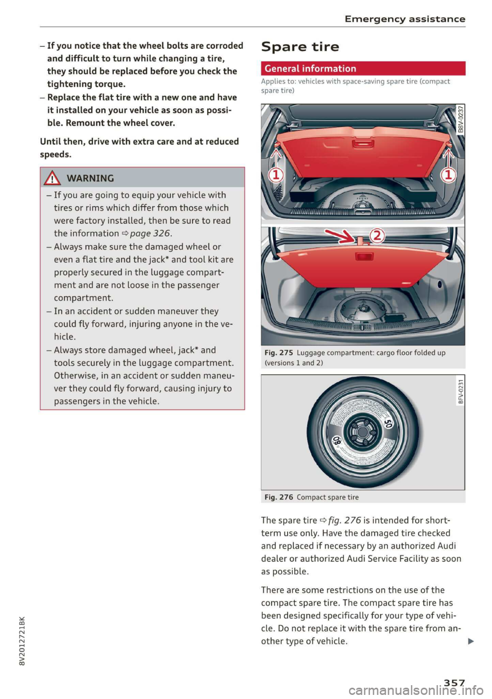
Fig. 275 Luggage compartment: cargo floor folded up
(versions 1 and 2)
BFV-0231
Fig. 276 Compact spare tire
The spare tire > fig. 276 is intended for short-
term use only. Have the damaged tire checked
and replaced if necessary by an authorized Audi
dealer or authorized Audi Service Facility as soon
as possible.
There are some restrictions on the use of the
compact spare tire. The compact spare tire has
been designed specifically for your type of vehi-
cle. Do not replace it with the spare tire from an-
other type of vehicle. >
357
Page 391 of 400

8V2012721BK
Plug-in hybrid drive range..............
also refer to Map............-0 eee eee
Navigation (instrument cluster) ......
O
Occupant protections. «+ ssa s+ wwe « een
Occupant seating positions..............
Octane rating (gasoline)................
OGGMEtEr acces s wows ¢ ¢ eee sy eS ee eS
ReSettinG) cc oc mxene ov wwe & osama 4 6 anes 2
Oil
referto Engine oil..................4.
On/Off kmnobi(MMI) sc = cevecs =o severe a x erence «
On Board Diagnostic System (OBD)...
Online destinations
refer to Point of interest search.........
Onlinemmap « ossicie 2 x cosence v sranene » waxes e 6 enue
Online map update.................0..
Online'Media.cc: « sevy 2 s ween ss eee ev eee
Online services
WE FEritOKCONMeCE is « swowes vv vase x x swonae wo oH
OPeniNG)s « = sess 2 & somes w comes ov meen & 3 oe
Convenience opening............-.00ees
Fuel filler door........... 0.00 e cece eee
Luggage compartment lid...............
Panoramic glass roof................0-5
PoWer top’ » = sews 2 + sew 2 o pews go ees 2 Bs
Windows ........- cee eee eee eee eee
Opening and closing
refer to Unlocking and locking.....
Operating
Multifunction steering wheel......... 17,
Multi Media Interface.................
Voice recognition system..............
OPtiONSANENU sess « & wcswexe ws ouswess
Outsidenoise « wieoc <5 eswe a 6 ewe ae eve ews
Overview (Cockpit)... 6.00.00 cece eeeees
Pp
Paifitidamage’: = 2 sees sv ewes « v seus ye eee
Paifitnumber: sacs « : noes ss vows sp eee se
Panic button........... 0.000 cece eee eee
162
81
Pani@ function’. « cess xo covsene oo omens ve soeoe oo 27
Panoramic glass roof..............000005 35
Convenience opening and closing......... 34
Emergency closing...........seeeeeeeee 35
Parental control
DVDs ¢ 2 nem 5 ¢ stuns = 8 aus 8s eee 2 8 222
ParkaSsist xeox = 2 eens = seten & » pose ee oes 140
Parkittg Si dias ¢ = sacen ¢ = SemR te eR x Beas 136
AQIUSTING pees x 2 sce ¢ o series va owen oo ssc 144
Cleaning the sensors and camera........ 343
Malfunction..............00 eee eee ee 145
Park:assist's < eine s + cea ox ees vo meee ye 140
RearvieWsGAMePalenene « ¢ eines « + csnsene © 6 weereue 138
Parking brake
refer to Electromechanical parking brake.. 87
Parking lights........ eee eee eee eee 43
Parking lock
Manually releasing................. 88, 89
also refer to Gears... 16... . eee eee eee ee 75
Pass-through secs s x sews x v ween se ees so os 63
PASSENGER AIR BAG OFF light........... 265
Pause (audio/video file)................. 219
Pedals... 0.0... cc cece eee 76, 241
PeRCLORAGE", « sovees sw misses ow snesame « ocecexe of © ane 374
Performance/torque display
refer to Sport displays.................. 24
Personal route assistance. ...........4.. 195
Phonebook
refer to ContactS.............02-0000- 178
Physical principles of a frontal collision.... 246
Picture format (video) .................- 222
Playback (media) sn. « sien 0 semis 0 0 atstere a eo 219
Playlistrcisia se scsi a a aves sw nm 6 w acer ¥ oo 222
Plug-in-Hybrid-Drive
High-voltage battery................0.. 96
Plug-in hybrid drive..............0.-005. 78
12 volt vehicle battery................ 365
Adjusting the modes.................-. 79
GIANG TAG cwcus 1c + cocoa wo atone © a mnewene = ewbente 97
Charging clip............. eee eee eee ee 103
Chargitigdotkie: = « eee s waren x 2 meee gs 3 102
Charging the high-voltage battery....... 101
Charging time...............0 2-00 104
Climate controle: « ¢ agus 9 s eww a 2 nme gag 68
COOLANE score < sxceans a exons = amoeane we wt nama 2 312
E-max (power availability)............... 80
Energy flow display.............--..0-. 80