display AUDI A3 CABRIOLET 2015 Owners Manual
[x] Cancel search | Manufacturer: AUDI, Model Year: 2015, Model line: A3 CABRIOLET, Model: AUDI A3 CABRIOLET 2015Pages: 302, PDF Size: 73.83 MB
Page 11 of 302
M N ,....
> co ...... \!) 1.1'1
...... 1.1'1 ......
CD
@
®
©
®
®
(J)
®
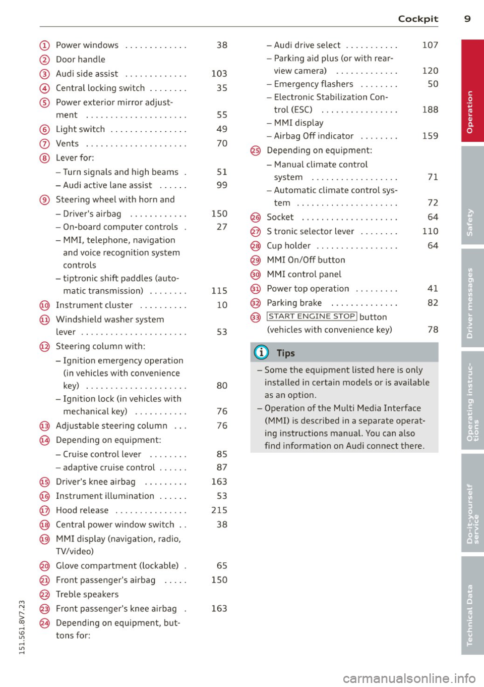
Power windows
Door handle
Aud i side assist ........ .... .
Centra l locking switch ... .. .. .
Powe r exter ior mirror adjust
ment
Light switch . ... .... ... .. .. .
Vents
L eve r fo r:
- Turn signals and high beams .
- Audi active lane assist ... .. .
® Steer ing wheel w ith horn and
- Drive r's airbag ........... .
- On-board computer controls
-MMI, telephone, navigat ion
and voice recogn it ion system
controls
- tiptron ic shift paddles (auto-
matic transmission) ....... .
@ Instrument cluster .. ... .. .. .
@ W indshield washer system
l ever
' .................... .
@ S teer ing column with:
- Ignit ion emergency operation
(in vehicles with conven ience
key) . .. ................. .
- Ignit ion lock (in vehicles with
mechanical key) .......... .
@ Adjustable s teer ing column
@ Depending on equipment:
- Cruise contro l lever ....... . 38
103 35
55
49
70
51
99
150 27
1 15
1 0
53
80
76
76
85
- adaptive cruise contro l . . . . . . 87
@ Driver's knee a irbag . . . . . . . . . 163
@ Instrument i llumination . . . . . . 53
@ H ood re lease . . . . . . . . . . . . . . . 215
@ Centra l power window swi tc h . . 38
@ MMI disp lay (navigation, radio,
TV/video)
@ Glove compartment ( lockable) . 65
@ Front passenger 's airbag . . . . . 150
@ Treble speakers
@ Front passenge r's knee ai rbag .
@ Depending on equipment, b ut
tons for: 163
Cockpi
t 9
-Audi drive select . .. ..... .. .
- P arking a id p lus (or w ith re ar-
view camera) . .. .. .. ..... .
- E mergency flashers ....... .
- Elect ron ic Stabilization Con-
t rol ( ESC) . .. .... ........ .
- MMI display
- Airbag Off indicator .... ... .
@ Depend ing o n equ ipment:
- Manual climate contro l
system
- Automatic climate control sys
tem
.. .. .. .. .. .. .........
Socket
S tronic se lector lever ..... .. .
Cup holder .. .. ............ .
MM I On/Off b utton
@ MMI control panel
@ Power top ope rat ion ... ..... .
@ Parking brake .... .. .. ..... .
@ I S T ART ENGINE STOPI button
(vehicles w ith convenience key)
(D Tips
107
120
so
188
159
71
72
64
110
64
41
82
78
- Some the eq uipment listed here is only
installed in certain models or is available
as an option.
- Operat ion of the Multi Med ia Interface
(MMI) is described in a separate operat
ing instructions manual. You can a lso
find info rmat ion on A udi connect ther e.
•
Page 12 of 302
10 Instrum ents a nd indi cato r lamp s
Instruments and indicator lamps
Instruments
Instrument cluster overview
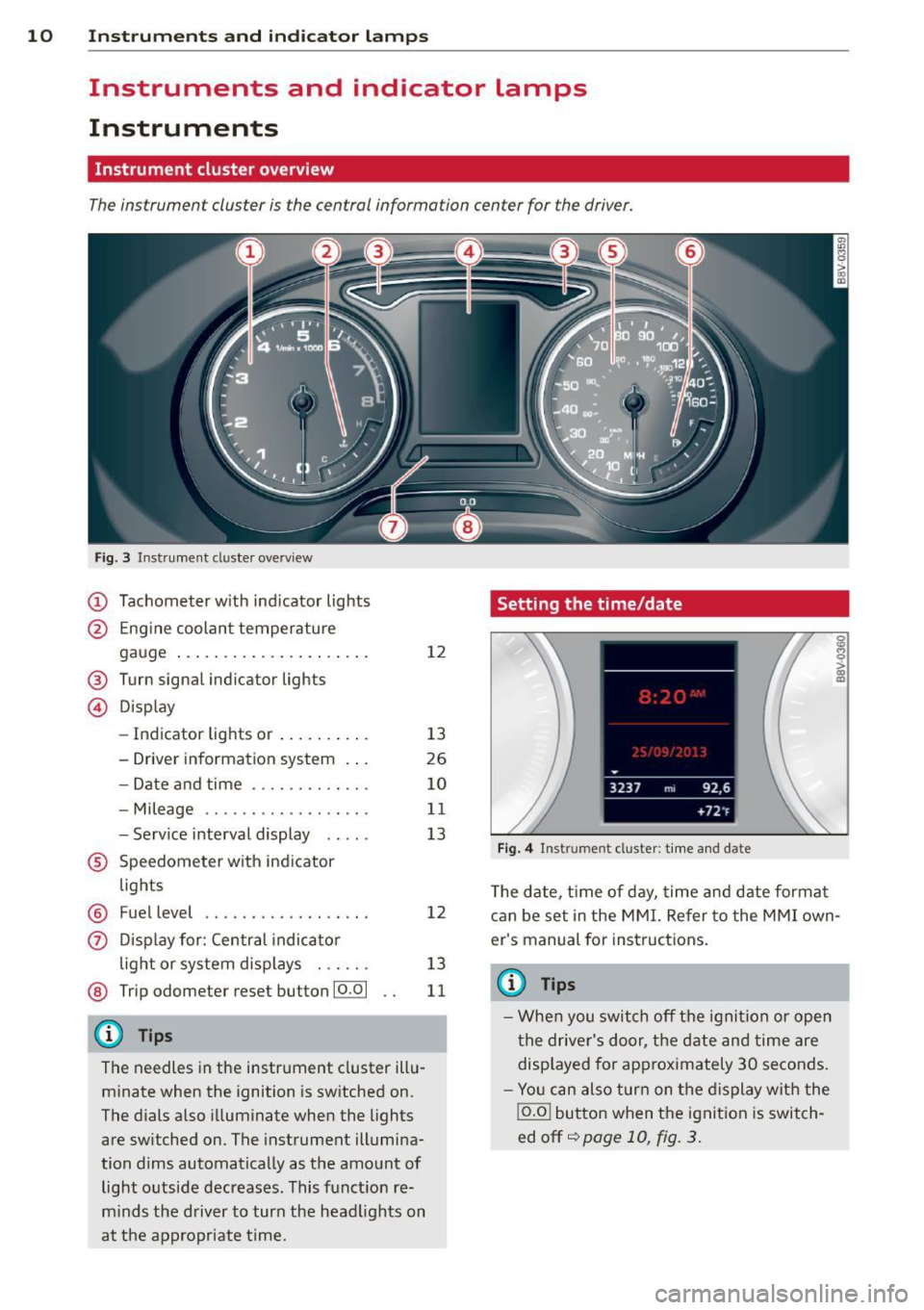
The instrumen t clus ter is the cen tral informa tion cen ter for the driver.
Fig . 3 In strument cl uster ove rv iew
(D Tachometer with ind icator lights
@ Eng ine coolant temperature
gauge .. ... .......... ... .. .
® Turn s ignal indi ca tor ligh ts
© D isplay
12
- Indicator light s or . . . . . . . . . . 13
- Driver information system . . . 26
- Date and time . .... .. ... .. .
- Mileage .. ... ..... .. ... .. .
- Serv ice interval disp lay .... .
® Speedometer with ind icator
lights
® Fuel level ................ . .
0 Disp lay for: Central indicator
l ight or system displays . .. .. .
@ Trip odome te r re se t bu tton 10.01
{D) Tips
The needles in the instrument cluster illu
minate when the ignition is switched on.
The dials also illuminate when the light s
are switched on . The instrument illumina
tion dims automatically as the amount of light outside decreases . This function re
m inds the driver to turn the head lights on
at the app ropriate time.
10
11
13
12
13
11
Setting the time/date
F ig. 4 Instrum en t cl ust er: tim e and date
T he date, t ime of day, time and date format
can be set in the MMI. Re fer to th e MMI own
er's manual for instruct ions.
(D Tips
- When you switch off the ignition or open
the driver's door, the date and time are
disp layed for approximately 30 seconds.
- Yo u can also turn on the display with the
j o.o j button when the ignition is switch
ed off ~
page 10, f ig. 3.
Page 13 of 302
....,
N
r--. > co
rl I.O
"' rl
"' rl
Tachometer
The tachometer displays the engine speed in
revolutions per minute .
The beginning of the red zone in the tachome
ter indicates the maximum permiss ible en
g ine speed for all gears once the engine has
been broken in and when it is warmed up to
operat ing temperature. You shou ld select the
"D/S" (Drive) selecto r lever pos ition or take
your foot off the accelerator peda l before
reaching th is area .
It is best to avoid high engine speeds, even
when dr iv ing in tiptron ic mode ~
page 115 .
(D Note
The tachometer needle
(D ¢ page 10,
fig. 3
shou ld only be in the red zone brief
ly: otherwise, this increases the risk of en
gine damage.
@) For the sake of the environment
Upshift ing early helps you to save fuel and
reduce operating no ise.
Odometer
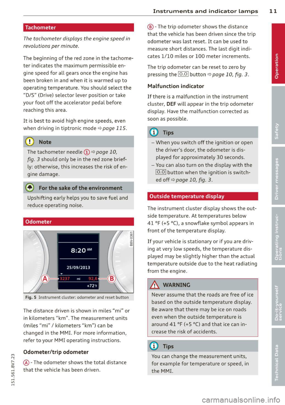
Fig. S In strument cl uster: odo meter an d reset butto n
The distance driven is shown in miles "mi" or
in kilometers "km" . The measurement units
(mi les "mi"
I kilometers "km") can be
changed in the MMI. For more info rmation,
refer to your M MI operating instructions.
Odometer /trip odom eter
@ -The odometer shows the total d ista nee
that the veh icle has been driven .
Instrument s an d indi cat or l amp s 11
@ -The trip odometer shows the distance
that the vehicle has been driven since the trip
odometer was last reset. It can be used to measure short distances. The last digit ind i
cates 1/10 miles or 100 meter increments .
The trip odometer can be reset to zero by pressing the
I o.o I button ¢ page 10, fig. 3.
Malfunction indicator
If there is a malfunct io n in the ins trumen t
cl uster,
DEF will appear in the trip odometer
display. Have the malfunction corrected as
soon as possib le .
(D Tips
- Whe n you switch off the ignit ion or open
the driver's door, the odometer is dis
played for approximately 30 seconds.
- Yo u can also turn on the display with the
j o.o j button when the ignition is switch
ed off~
page 10, fig . 3.
Outside temperature display
The instrument cluster display shows the out
s ide temperature. At temperatu res below
41 °F (+S °C), a snowf lake symbol appears in
front of the temperature display .
If your vehicle is stationary or if you are driv
ing at very low speeds, the temperature d is
played may be slightly higher than the actual
temperatu re outs ide due to the heat rad iating
from the engine.
,&. WARNING
N eve r assume that the roads a re free of ice
based on the outside temperature display.
Be awa re that there may be ice on roads
even when the outside temperature is
around 41 °F ( +S °C) and that ice can in
crease the risk of accidents.
(D Tips
You can change t he measurement un its,
for example fo r temperature or speed, in
the MMI.
Page 14 of 302
12 Instrum ent s and indicator lamp s
Fuel level
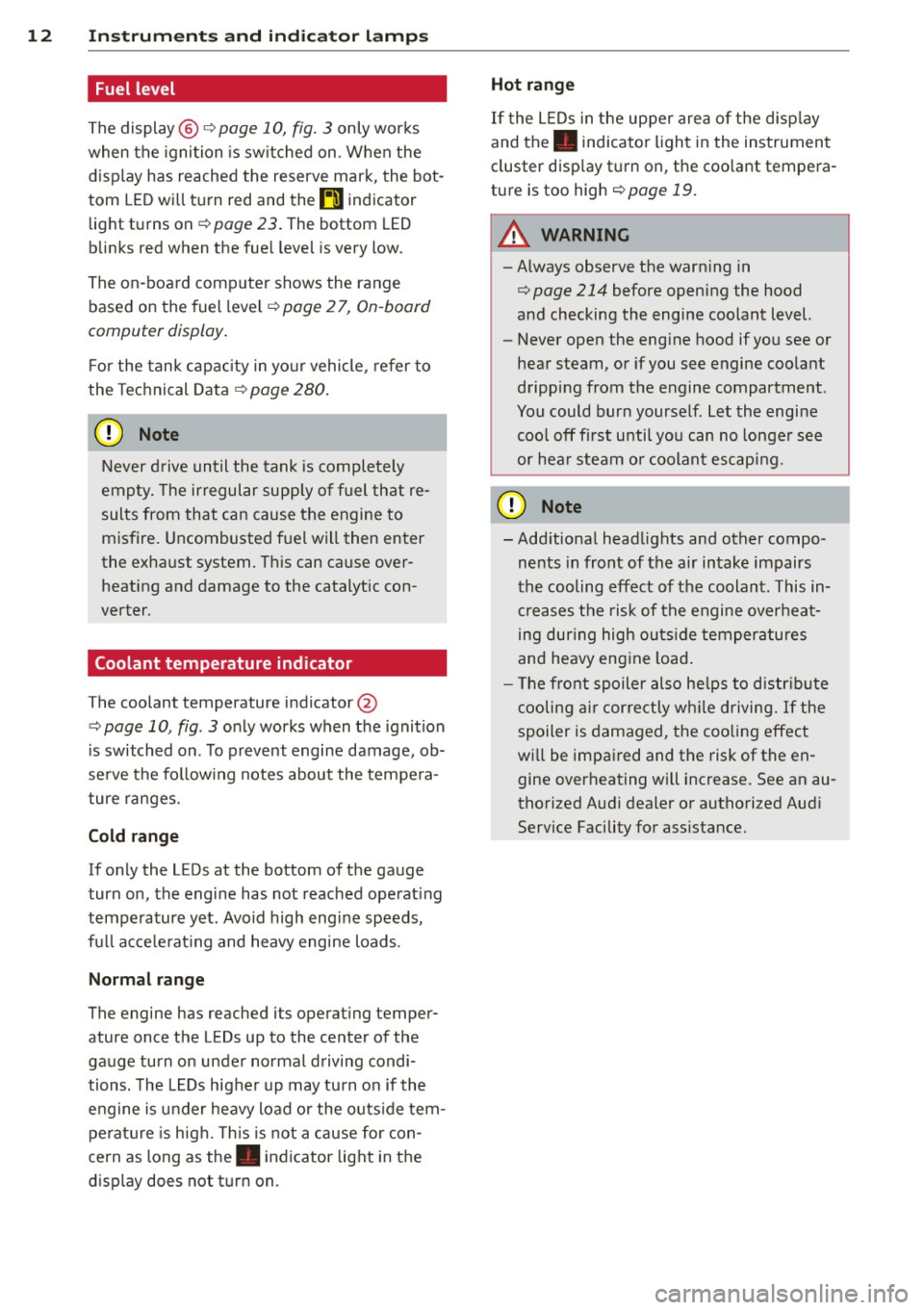
The display @
c;, page 10, fig. 3 only works
when the ignition is sw itched on . When the
d isplay has reached the reserve mark, the bot
tom LED wi ll turn red and the
tD indicator
light turns on¢
page 23 . The bottom LED
blinks red when the fue l level is very low .
The on -board computer shows the range
based on the fuel leve l
c;, page 2 7, On-board
computer display.
F or the tank capac ity in yo ur vehicle , refer to
the Tec hnical Data ¢
page 280.
CJ) Note
Never d rive until the tank is completely
empty. The irregular supp ly of fuel that re
sults from that can cause the engine to
misfire. Uncombusted f uel will then enter
the exha ust system. This can cause over
heating and damage to the catalytic con
verter .
Coolant temperature indicator
The coolant temperature ind icator @
c::> page 10, fig . 3 only works when the ignition
is switched on . T o prevent engine damage, ob
serve the fo llow ing notes about the tempe ra
ture ranges.
Cold range
If only the LEDs at the bottom of the gauge
turn on, the engine has not reached operat ing
temperature yet . Avoid high engine speeds,
fu ll acce le rat ing and heavy engine loads.
Norm al range
The engine has reached its operating temper
ature once the LEDs up to the center of the
gauge turn on under normal driving condi
tions. The L EDs higher up may turn on if the
engine is under heavy load or the o uts ide tem
perat ure is h igh. This is not a cause for con
cern as long as the. indicator light in the
display does not t urn on. Hot range
If the L
EDs in the upper area of the d isp lay
and the. indicator light in the instrumen t
cluster disp lay t urn on, the coo lant tempe ra
ture is too high
c::> poge 19.
A WARNING
-Always observe the warning in
c;, page 214 before opening the hood
and checking the engine coolant level.
- Never open the eng ine hood if you see or
hear steam, or if you see engine coo lant
dripping from the engine compartment .
You could burn yourself. Let the engi ne
coo l off first until you can no longe r see
or hea r steam or coolant escaping.
([) Note
- Add itiona l headlights and other compo
ne nts in front of the a ir intake impairs
the cooling eff ect of the coolant. This in
creases the risk of the engine over heat
ing dur ing high outs ide temper atures
and heavy eng ine load .
- The front spoiler also he lps to distr ibute
cooling air correct ly wh ile driving.
If the
spoiler is damaged, the coo ling effect
wi ll be impai red and the risk of the en
gine overheating will increase. See an au
thorized Audi dealer o r authorized Aud i
Service Facility for ass istance.
Page 15 of 302
....,
N
r--. > co
rl I.O
"' rl
"' rl
Service interval display
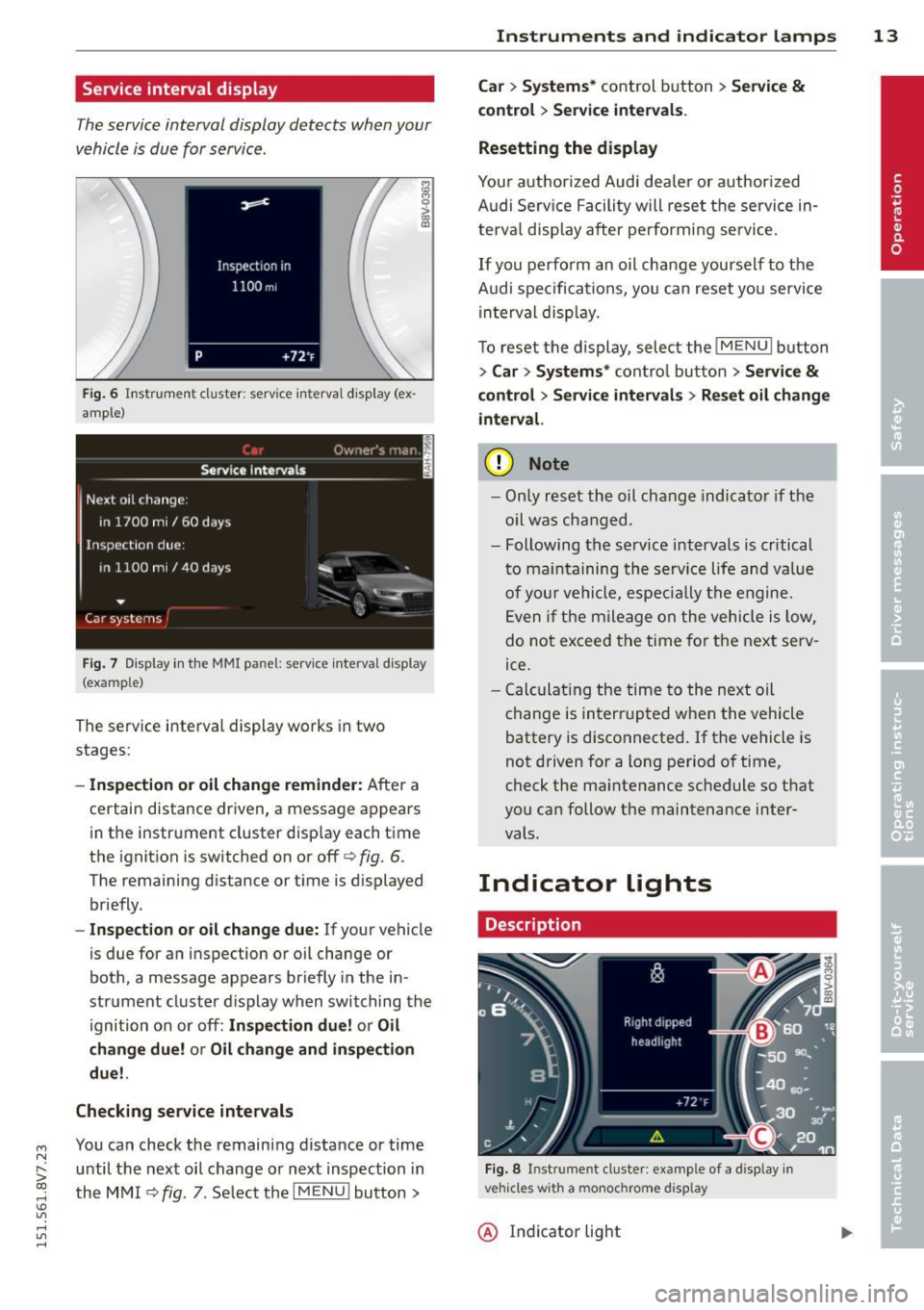
The service interval display detects when your
v e hicle is due for service .
Fig. 6 In str um en t cluste r: serv ice inte rva l d isp lay (ex
a m ple)
Fig. 7 Disp lay in th e MMI panel: se rv ice interval display
(exa mple )
The serv ice interva l display works in two
stages:
- Inspection or oil change reminder : After a
certain distance driven, a message appears
i n t he instr ument cluster d isp lay each time
the ignit ion is switched on or off
r=> fig. 6.
The remaining distance or t ime is d isplayed
briefly.
- Inspect ion or oil change due : If your vehicle
is due for a n insp ection or o il change or
bot h, a message appears br iefly in the in
strument cluster d isplay when switching the
ignition o n or off:
In spection due! or Oil
change due! or Oil change and in spection
due!.
Checking service intervals
You can check the remaining distance or time
until the nex t oil change or next inspection in
the M MI
¢ fig. 7. Se lect t he I MENU ! button >
Instruments and indicator lamps 13
Car > Systems* control button > Service &
control
> Service intervals .
Resetting the display
Your a uth orized Audi dea le r or auth oriz ed
A udi Se rv ice F acility will rese t the service in
te rv al disp lay after pe rfo rmi ng se rvice.
I f you perfo rm an o il change you rself to the
A udi spe cifications, yo u can reset yo u service
in terval disp lay.
T o reset the display, select the
!ME NUI button
> Car > Sy stem s* control button > Service &
control
> Servi ce interval s > Reset oil change
interval.
(D Note
- On ly r eset th e oil chang e indicato r if th e
oil was cha nged.
- Following the se rv ice intervals is critical
t o m ain ta ini ng th e se rv ic e life a nd val ue
o f yo ur v ehicl e, espe cially th e e ngine.
E ven i f the mile age on t he vehicle i s low,
d o no t exceed the time for th e nex t serv
ice.
- Calcu lating t he time to the next oil
c hange is in te rrupt ed whe n the vehicle
battery is dis connected. If t he vehicle is
n ot d riven f or a long period o f time,
check the ma intenance schedule so th at
you ca n follow the maintena nce inter
vals.
Indicator lights
Description
Fig. 8 Instrum en t cluste r: example of a display in
vehicles wit h a mo noc hrome display
@ Ind icator light
Page 16 of 302
14 Instruments and indicator lamps
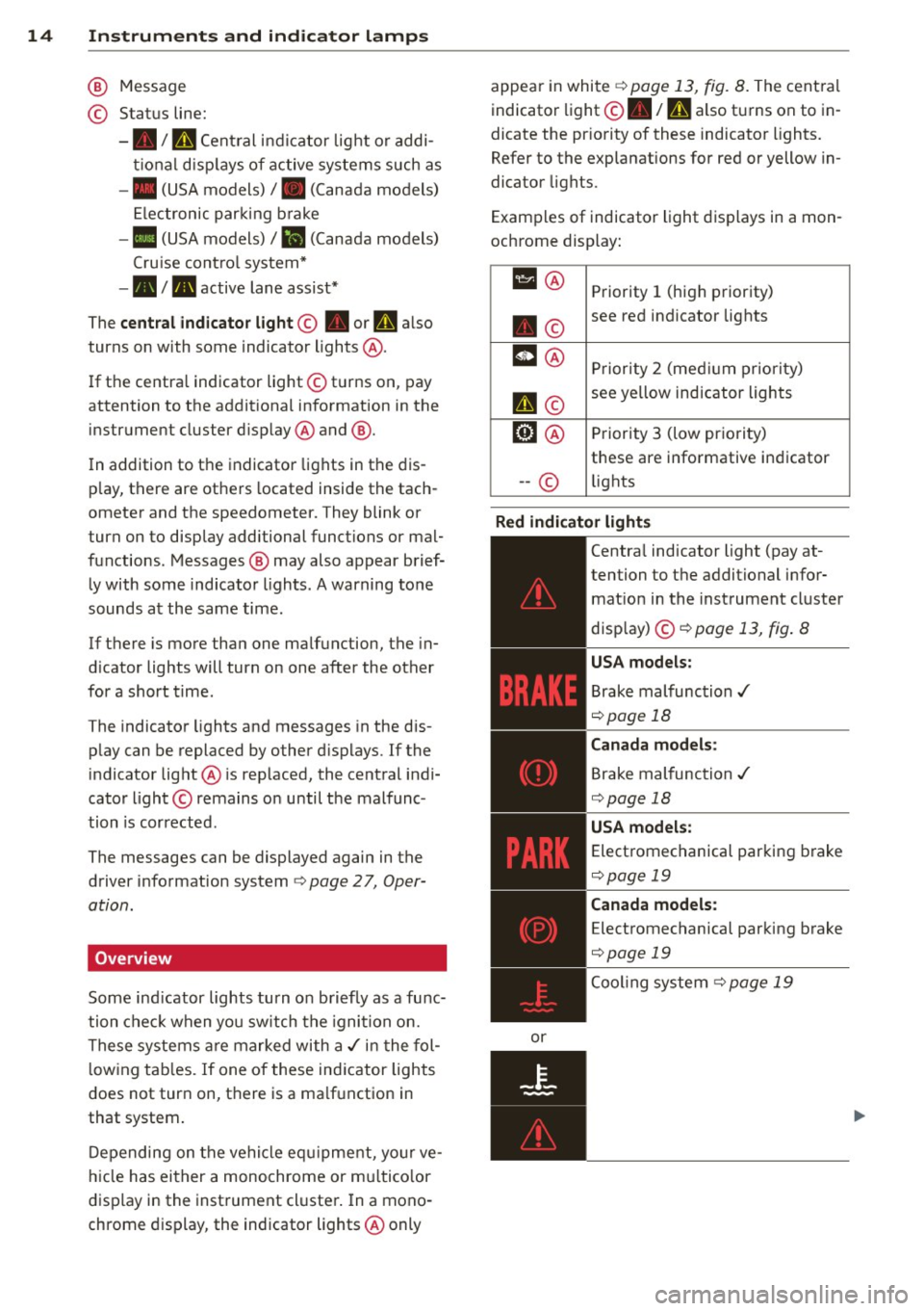
@ Message
© Status line:
-• I U Central indicator light or addi
tional displays of active systems such as
- • (USA models)/ . (Canada models)
El ectronic parking brake
-• (USA models)/
Iii (Canada models)
Cruise control system*
- • I. active lane assist*
The
central indicator light© • or I'll also
turns on with some indicator lights @.
If the centra l indicator light © turns on, pay
attention to the additional information in the
instrument cluster display @and @.
In addition to the indicator lights in the dis
p lay, there are others located inside the tach
ometer and the speedometer. They blink or
turn on to display additional funct ions or mal
functions. Messages@ may also appear brief
ly with some indicator lights. A warning tone
sounds at the same time .
If there is more than one malfunction, the in
d icator lights will turn on one after the other
for a short time.
The indicator lights and messages in the dis
p lay can be replaced by other displays. If the
indicator light@ is rep laced, the central indi
cator light © remains on until the malfunc
tion is corrected.
The messages can be displayed again in the
driver information system
<=>page 27, Oper
ation.
Overview
Some indicator lights turn on briefly as a func
tion check when you switch the ignition on.
These systems are marked with a./ in the fol
l owing tab les. If one of these indicator lights
does not turn on, there is a ma lfunction in
that system .
Depending on the vehicle equ ipment, your ve
hicle has either a monochrome or mu ltico lor
display in the instrument cluster. In a mono
chrome display, the indicator lights@only appear
in white
<=>page 13, fig. 8. The cent ral
indicator light@• /
mi also turns on to in
dicate the pr iority of these indicator lights.
Refer to the explanations for red or yellow in
dicator lights.
Examples of indicator light displays in a mon
ochrome display:
111 @ Priority 1 (high priority)
. © see red
indicator lights
m@ Priority 2 (medium priority)
I'll©
see yellow indicator lights
ml@ Priority 3 (low pr iority)
these are informative indicator
-- © lights
Red indicator lights
or
-------------
Centra
l indicator light (pay at-
tention to the additional infor mat ion in the instrument cluster
disp lay) ©<=>
page 13, fig . 8
USA models :
Brake malfunction ./
<=>page 18
Canada models:
Brake malfunction./
<=>page 18
USA models :
Electromechanical parking brake
<=>page 19
Canada models :
Electromechanical parking brake
<=>page 19
Coo ling system r=> page 19
Page 28 of 302
26 Driver information system
Driver information
system
Overview
Ap plies to vehicles: with d river in format ion syste m
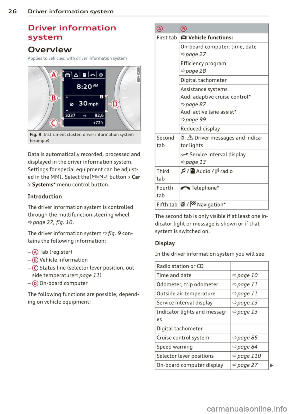
Fig. 9 Instrument cluster: driver informat ion system
(example)
Data is automatically recorded, processed and
d isplayed in the driver information system.
Sett ings for special equipment can be adjust
ed in the MMI. Select the
I MENU ! button> Car
> Systems* menu control button .
Introduction
The driver information system is controlled
through the multifunction steering wheel
c::;, page 2 7, fig. 10.
The driver information system c;, fig. 9 con
tains the following information:
- @ Tab (register)
-@ Vehicle information
-© Status line (se lector lever posi tion, out-
s ide temperaturec:=;,
page 11)
-@ On-board compute r
The following functions are possible, depend ing on vehicle equipment: @
®
First tab ~ Vehicle
functions:
On-board computer, time, date
c:=;,page 27
Efficiency program
c:=;,page28
Digital tachometer
Assistance systems
Audi adaptive cruise control*
¢page87
Audi active lane ass ist*
¢page99
Reduced display
Second
tJ. 6 Driver messages and ind ica-
tab tor lights
c,,..c Service interval display
c:=;,pag
e 13
Third fl I I Audio/ i»> radio
tab
F ourth .,..,.
Telephone*
tab
Fifth tab
~I~ Navigation*
The second tab is only visible if at least one in
dicator light or message is shown or if that
system is switched on .
Display
In the driver information system you will see:
Radio station or CD
Time and date
¢page 10
Odometer, trip odometer ¢page 11
Outside air temperature ¢page 11
Service interval display c::;, page 13
Indicator lights and messag-¢page 13
es
Digital tachometer
Cruise control system
c:=;,page 85
Speed warn ing c:=;,page 84
Selector lever positions c::;, page 110
On-board computer display c::;, page 27 ...
Page 29 of 302
....,
N
r--. > co
rl I.O
"' rl
"' rl
On-board computer display
The on-boa rd comp uter display monitors the
d iffe rent memory levels:
- Sho rt-term memory (on-board computer
1)
- Long-term memory (on-board computer 2)
-Eff iciency p rogram
The fo llowing information can be displayed in
on-boa rd compute r
1 and 2 one after the oth
er.
- Date
- Estimated range based on current fuel leve l
- T rave l time
- Average consumption
- Average speed
- Distance
- Current fuel consumption
On-board computer D (short -te rm
mem ory )
The sho rt-term memory co llects d riving infor
mation from the time the ignition is switched
on until it is switched off . If you continue driv
ing
w ith in two hours after switc hing the igni
tion off, the new values a re included when cal
culating the cu rrent trip information .
If stop
ped for more the two hours, the short term
memory is automatically erased once you be
g in d riving.
On-board computer fJ (long-term
memory )
Unlike the short-term memory , the long -term
memory is not erased automa tica lly. You can
selec t the time pe riod for evaluat ing t rip in
formation yo urself.
Efficiency program ii
The eff ic iency program can help you to use
l ess fuel ¢
page 28.
(D Tips
-The on-board computer is controlled by
the left but ton fields on the multifunc
tion steering wheel.
- For information on using the other but
ton fields, such as the aud io, telephone*
Dr iver in formation system 2 7
and navigation* f unct ions, see the M MI
owner's manual.
Operation
Applies to veh icles: w ith driver information system
T he dr iver information system is controlled
with the multifunction steering wheel.
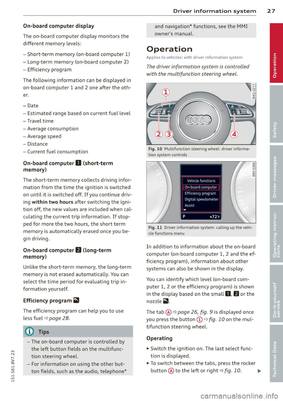
F ig . 1 0 Mu lt ifun ction s tee rin g w heel : d river i nforma
t ion s ystem c ontro ls
F ig . 1 1 Driv e r in forma tion syst em: calling up the vehi
cle funct io ns me nu
In add ition to information about the on-board
computer (on -board computer 1, 2 and the ef
ficiency program), informa tion about othe r
systems can also be show n in the display .
You can identify which level (on-board com
puter 1, 2 or the efficiency program) is shown
i n the d isp lay based on the sma ll
0, fJ or th e
no zzle
ii .
The tab@¢ page 26 , fig. 9 is displayed once
you press the b utton
(D ¢ fig. 10 on the mul
tif unctio n steer ing wheel.
Operating
.. Switch the ignit ion on. The last select func
tion is disp layed.
.,. To switch between the tabs, press the rocker
button @to the left or right¢
fig. 10. IJJJ,
Page 30 of 302
28 Driver information system
• To access additional in formation be low or
above, rotate the thumbwheel @dow n or
up .
• To confirm a se lection, press the thumb
whee l@ .
• To select a fu nction programmed to a steer
i ng w heel button, p ress the bu tto n@ . Fo r
additional information, see
9 page 28, As
signing a fun ction to the programmable
s teering wheel button
Calling up the Vehicle functions
> Se lect the first tab w ith the button @.
• Press the button @. The
Vehicle functions
me nu is displayed 9 fig . 11 .
• To se lec t a menu item, turn and p ress the
t hu mbwheel @.
Resetting values to zero
• In the Vehicle functions menu, se lect On
board computer or Efficiency program .
• Se lect a va lue in th e desired t rip computer
o r i n the efficiency program.
• To reset the va lues i n a memo ry, press and
ho ld the thumbwhee l@ for one second.
Recalling indicator lights and messages
.. Pr ess the button CD repeate dly until the a
tab appears .
The
U tab is only vis ible whe n there is a mal
f u nction.
Assigning a functi on to the
programmable steering wheel button
> Se lect: the I MENU ! button >Car > Systems*
co ntrol button > Vehicle settings > Ste ering
wheel button programming .
The U tab is only visible whe n there is at
least one i ndicator light or message d is
p layed .
@ Tips
-If the vehicle battery is d iscon nected, all
memo ry values are e rased .
- Informati on on the efficiency program
¢ page 28.
- There is more in formation on the m ulti
function stee ring w heel in the
M MI*
owne r's manual.
Efficiency program
Description
Applies to vehicles: with driver informat ion system
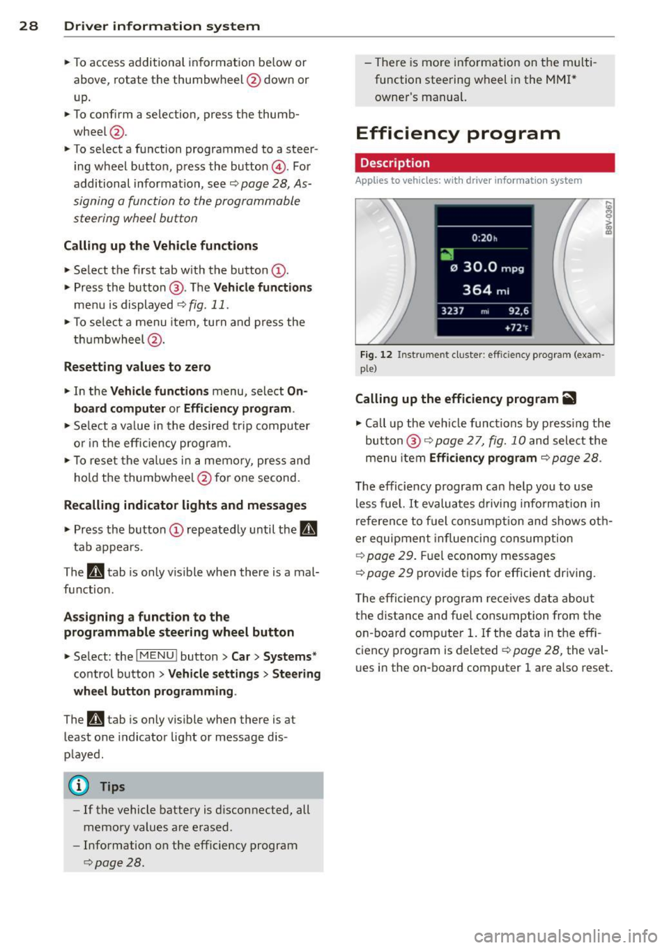
Fig . 12 Instrume nt cluste r: effi cie ncy progra m (exa m
p le)
Calling up the efficiency program ii
• Call up the veh icle func tions by press ing the
bu tton @
9 page 2 7, fig. 1 0 and select the
menu item
Efficiency program 9 page 28.
The effici ency program ca n he lp you to use
less fue l.
It evaluates d riving info rmation in
refe ren ce to f uel consum ption and shows ot h
er equipment in fluencing cons umption
9 page 2 9. Fuel economy messages
9 page 29 prov ide t ips for efficie nt dr iv ing .
T he efficiency progr am re ce ives da ta abou t
t h e di sta nce and fue l cons ump tion from the
on -board com puter
1. If the data in the effi
c iency p rog ram is deleted
¢ page 28, the va l
u es i n the on -board computer 1 are a lso reset .
Page 31 of 302
....,
N
r--. > co
rl I.O
"' rl
"' rl
Other equipment
Applies to vehicles: with driver information system
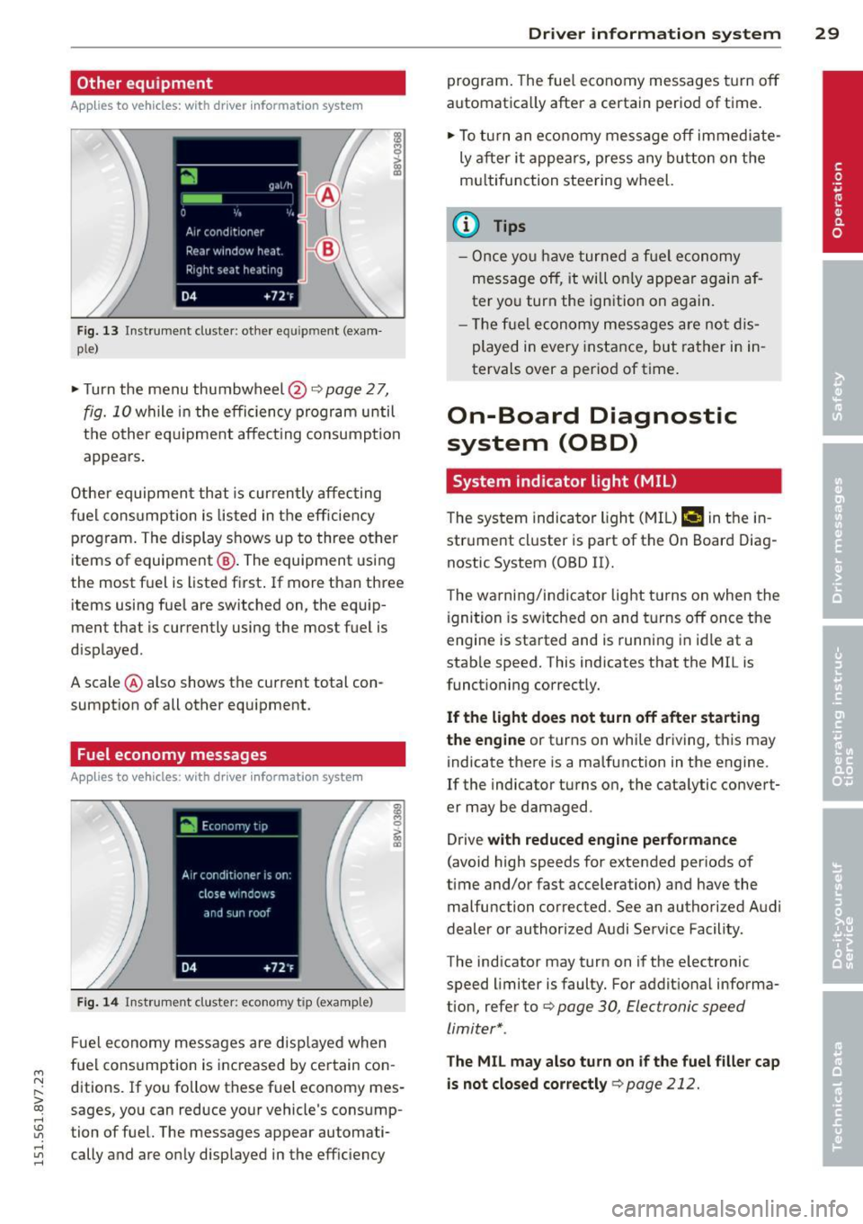
F ig. 13 Instrument cluster : other equ ipment (exam
p le)
~ Turn the menu thumbwheel@Qpage 27,
fig. 10 while in the efficiency program until
t h e other eq uipme nt affect ing consump tion
appears .
Other equipmen t that is curren tly affecting
fuel cons umption is listed in t he eff iciency
p rog ram. The display shows up to three other
items of equipment @. The equipment using
the most f uel is listed first . If more than three
items using fue l are switched on, the equip
ment that is currently using the most fuel is
d isplayed .
A scale @ also shows the current total con
sumpt ion of all other equipment.
Fuel economy messages
App lies to vehicles: with driver information system
Fi g. 14 Instrument cluster : economy tip (examp le)
F ue l economy messages are disp layed when
fuel consumption is inc reased by certain con
ditions. If yo u follo w these fuel economy mes
sages, you can reduce your vehicle's consump
tion of fuel. The messages appear automati cally and are o nly displayed in the eff ic iency
Dr iver in formation system 29
program . The fue l economy messages t urn off
automatica lly after a certain period of time.
~ To tu rn an e conomy me ssage off immed iate
ly a fter it appea rs, press any bu tton on the
m ultifunction stee ring wheel.
(D Tips
- O nce yo u have turned a f uel economy
mess age off, it will o nly appear ag ain a f
ter yo u turn the ign ition on again.
- Th e fu el economy mess ages are no t dis
played in every instance, but rather in in
tervals over a period of time .
On-Board Diagnostic
system (OBD)
System indicator light (MIL)
The system indicator ligh t (M IL) ¢.§ in the in
str ument cl uster is part of the On Board Diag
nostic System (OBD II).
T he warni ng/i ndicator light t urns on when the
ignition is sw itched on and t urns off once the
engine is sta rted and is runn ing in id le at a
stab le speed. This indicates that the MIL is
funct ioning correct ly.
If the light does not turn off after sta rting
the engine
or turns on while driving, t his may
indicate there is a ma lfunction in the engine.
If the indicator turns on, the cata lytic convert
er may be damaged .
Drive
with reduced engine performance
(avoid high speeds for extended periods of
time and/or fast acceleration) and have the
malfunction corrected. See an authorized Audi
dealer or author ized Audi Service Facility.
The indicator may turn on if the electronic
speed limiter is faulty. For addit ional informa
tion, refer to Q
page 30, Electronic speed
limiter* .
The MIL may also turn on if the fuel filler cap
is not closed cor rectly
q page 212.