auxiliary battery AUDI A3 SEDAN 2018 Owners Manual
[x] Cancel search | Manufacturer: AUDI, Model Year: 2018, Model line: A3 SEDAN, Model: AUDI A3 SEDAN 2018Pages: 404, PDF Size: 62.3 MB
Page 113 of 404
u. 00 .-< N l' N .-< 0 N > 00
A./ appears in the box. This activation is sepa
rate from the Infotainment system settings in
the climate control menu
¢ page 116.
~ Press the I BACKI button.
~ To activate the desired timer, confirm the set
ting with the control knob.
A,/ appears in the
box .
Power save mode
Power save mode is automatically switched on
when the control unit has not been operated for
more than one minute. The
LEO @¢ page 109,
fig. 115 stays on. All other displays turn off.
~ To switch power save mode on or off, press the
~ button @¢page 109, fig. 115.
Power save mode ends automatically when the
vehicle charging connector is plugged into the ve
hicle.
The high-voltage battery is charging when the
LED@ blinks.
(D Tips
-Auxiliary climate control is powered electri
cally if you select climate control using the
charging timer. This may also be used in
confined spaces such as garages.
- Using the auxiliary air conditioning while
charging can also reduce the charge level of
the high-voltage battery.
- The high-voltage battery also charges in
power save mode.
- If the charging process is in progress, it will
not be interrupted when power save mode
switches on.
- The charging process can be interrupted at
any time. Press the active button on the ve
hicle to do this
¢page 109, fig. 116.
-The climate control output while charging
depends on the capacity of the electrical
connection. Additional information on cli
mate control can be found under
¢page 116.
e-tron
Setting the charging power level
App lies to : veh icles w it h pl ug-in hybr id drive
The control unit automatically recognizes the
voltage and the available current strength. You
can set whether you would like to charge with the
full or half of the charging power.
~ Press the I OKI@ ¢ page 109, fig. 115 button
on the control unit.
~ Enter the PIN if necessary.
~ POWER and SET PIN appear in the display
field.
~ Select POWER with the arrow button @.
~ Press the I OK I button @.
~ The charging power display appears. The cur
rent set value (50% or 100%) is marked with a
frame.
~ If necessary, change the setting using the ar
row button © to move downward or upward.
~ Press the I OK I button @.
(D Tips
- If a household socket is used for the charg
ing process, the charging power level is au
tomatically set to 100%. If multiple electri
cal consumers are connected to a circuit
'
the charging power may be limited to 50%
when charging with a household socket in
order to relieve the load on the electrical in
stallation.
- If an industrial socket is used for the charg
ing process, the charging power level is au
tomatically set to 50%. To receive the maxi
mum charging power, the value must be set
to 100% .
- A selected value remains set until the power
cable is connected again.
111
Page 118 of 404
e-tron
Applies to: vehicles with Audi virtual cockpit mt
Incompatible ch arging s ystem . Please check
c harging system
Applies to: vehicles with analog instrument clus
ter:
mt AC charging : currentl y not po ssible
This message appea rs whe n the charg ing system
is incomp atib le. O nly charge usi ng the charg ing
system tha t is designed fo r you r vehi cle.
mt AC charg ing sy stem: malfunction! Pl ease
c ontact Service
This message appears if there is a ma lfunction in
the charg ing system . H ave the problem corrected
immed iate ly by an authorized Aud i dealer or au
thor ized Audi Se rvice Facility.
Charging unit cover
emergency release
Applies to: vehicles with plug-in hybrid drive
Fig . 120 Fron t of th e ve hicle: cover e merge ncy re lease
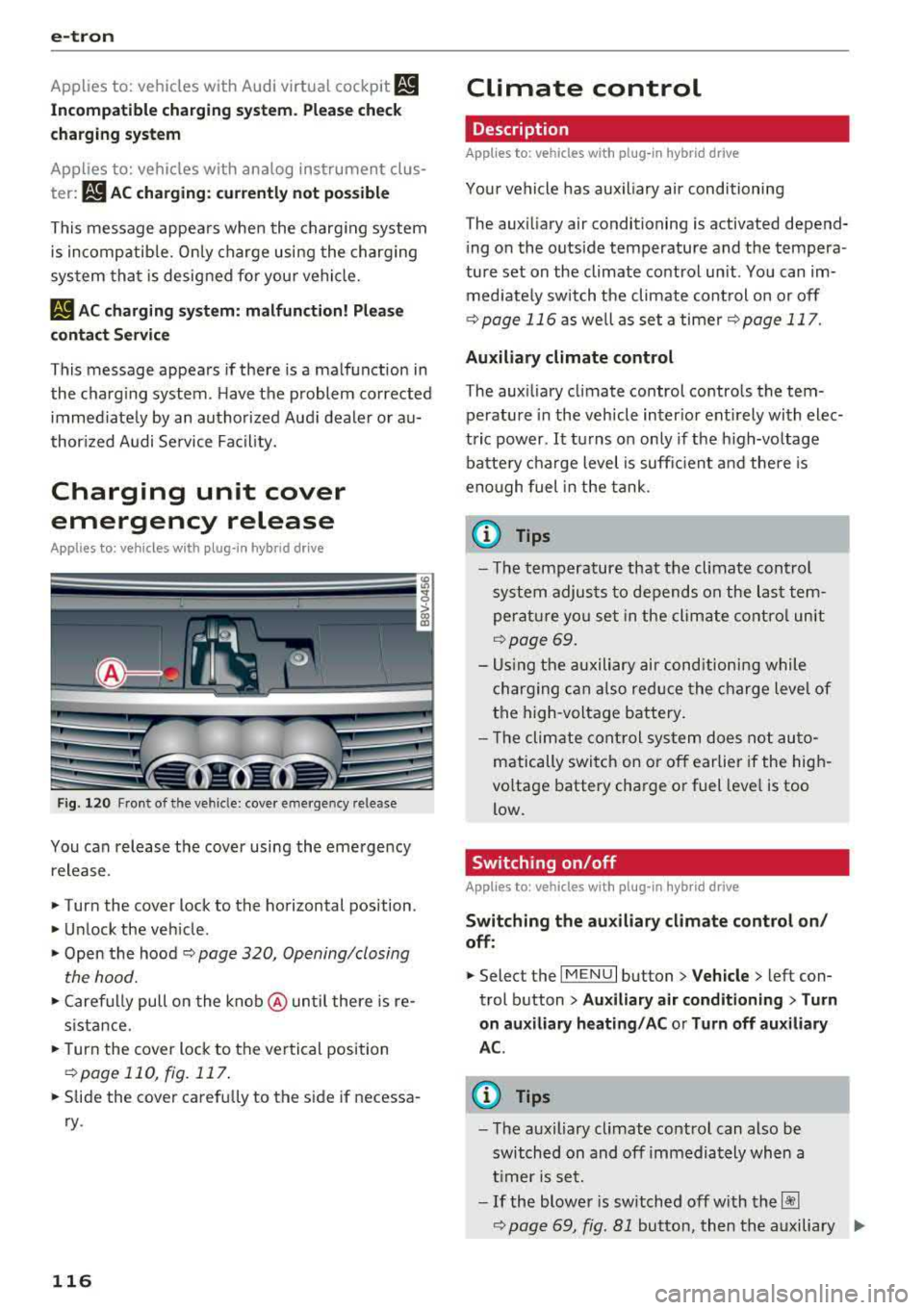
You can release the cover using the eme rgency
release.
• Turn the cover lock to the horizontal position .
• Unlock the vehicle .
• Open the hood ~ page 320, Opening/closing
the hood.
• Caref ully pull on the k nob @ until there is re
s ista nce.
• T urn the cover lock to the ver tical position
~ page 110, fig. 117 .
• Slide the cover carefu lly to the s ide if necessa
ry .
116
Climate control
Description
Applies to: vehicles with plug-in hybrid drive
Your vehicle has aux iliary air conditioning
T he aux iliary air conditioning is activated depend
i ng on the outside temperature and the tempera
ture set on the climate control unit. You can im
med iate ly switch the climate cont rol on or off
¢ page 116 as well as set a timer r::;,page 117.
Auxiliary climate control
The aux iliary climate contro l contro ls the tem
perature in the veh icle inter ior ent irely with elec
tric power .
It turns o n on ly if the h igh-vo ltage
batte ry cha rge level is suff ic ient a nd there is
eno ugh fuel in the tank .
@ Tips
- The temperature that the climate control
system adjus ts to depends on the last tem
perat ure yo u se t in the climate contro l unit
¢ page 69.
- Us ing the auxiliary air cond itioni ng while
charging can also red uce the c harge leve l of
the high-voltage battery .
- T he clim ate cont rol sys tem does no t au to
matically switc h on o r off earlier if the hig h
voltage battery cha rge or fuel leve l is too
low.
Switching on/off
Applies to: vehicles with plug-in hybrid drive
Switching the auxiliary climate cont rol on /
off :
• Select the I MENU I button> Vehicle > left con
trol b utton >
Auxiliary air conditioning > Turn
on auxiliary heating / AC or Turn off auxiliary
A C.
(D Tips
- T he auxiliary climate contro l can also be
switched on and off immedia tely wh en a
t imer is se t.
-If the blower is switched off w ith t he~
~ page 69, fig. Bl button, then the auxiliary .,..
Page 119 of 404
air conditioning also switches o ff immedi
ate ly.
Setting the timer
A ppl ies to: ve hicles w ith plug- in hybrid drive
By setting the departure time, you determ ine
when your vehicle shou ld reach the desired tem
perature. You ca n set the timer in the auxiliary air
conditioning menu in the Infota inment system .
Auxili ary climate c ontrol : sett ing the t imer
~ Se lect : IMENUI button> Vehicle > left control
button >
Au xiliar y A/C > right control b utton>
Program t imer .
~ Set the time and the date.
~ Press the I BACKI button .
~ Confirm the setting w ith the contro l knob to ac-
t ivate the t imer.
A./ appea rs i n the box .
When you reprogram a t imer, the next calendar
day is automat ically entered in the Infota inment
system. To act ivate the aux iliary climate control
fo r the next day, confirm t he sett ing(./ in the In
fotainmen t system).
Error messages
ea -The high -voltage battery charge level is too
low to heat/air condition the veh icle using only
e lectr ic powe r.
If one of the follow ing symbols appears in the
d isplay, then you cannot switch on the aux iliary
climate cont rol:
,....c -There is a system ma lfunction.
Bu -The fue l level is too low.
(D Tips
- You can set the t imer a m axim um of seve n
days in advan ce.
- You can operate the clima te con trol in the
vehicle inte rior w hen the h igh -vo ltage bat
tery is charging using the c harging timer
¢ page 110 . The climate cont rol output de
pends on the powe r socket capac ity.
::li -M ake s ure the time and date match in the .-<
~ Infotainment system settings so that the
N 8 timer can function properly¢ page 243.
N > 00
e-tron
- T he auxiliary climate contro l can contin ue to
ru n after the departure time is reached .
Cleaning/maintenance
information
App lies to : vehicles wi th plug-in hybrid drive
When was hing your vehicle with a pressure wash
er, always follow the operat ing instruct ions pro
v ided w ith the pressure washer. This is especially
i mportant in regard to the pressu re and spray ing
distance. Do not direct cleaning spray at the
c h arg ing unit in the rad iator g rille or at t he
c h arg ing dock*/charging cl ip*. Keep a d istance of
at least 16 in (40 cm) .
Do not remove snow and ice with a p ressure
washe r.
Never use cone nozzles or high pressu re nozzles .
The water temperature must not be above 60
°C.
Remove contaminants on the Audi e -tron system
with a dry towel.
Remove contaminants on the charging dock*/
c h arg ing clip* wi th a wet towe l dampened w ith
alcohol-free clean ing solution .
& WARNING
=
-Never immerse the Audi e-tron charging
system and connectors in water.
-
- The A udi e -tron charging system must on ly
be cleaned when the control unit is com
p letely disconnected from the power supp ly
and from the vehicle.
@ Note
To dec rease the risk of discolora tion, never
clean the charging doc k*/charging clip * with
harsh cleaning sol utions or so lutions that
contain alcoho l.
117
Page 321 of 404
u. 00 .-< N l' N .-< 0 N > 00
-If tests need to be performed with the en
gine running, there is additional danger due
to moving components (such as the ribbed belt, alternator and radiator fan) and from
the h igh-voltage ign it ion system .
- Never reach into the radiator fan. The elec
tric auxiliary fan is controlled by tempera
ture and can switch on suddenly .
- Do not under any circumstances activate the
throttle inadvertently (for example, by hand
from the eng ine compartment) if the vehi
cl e is stationa ry but the engi ne is ru nning
and a gear is engaged. Ot herw ise, the vehi
cl e w ill sta rt to move immediately and t his
cou ld res ult in an accident .
- Pay atte ntion to the fo llow ing war nings list
ed when work on the fuel system or on the
electrical eq uipment is required.
- Do not smoke .
- Never work near open flames.
- Always have a working fire extinguisher
nearby.
- All work on the battery or e lectrica l system
in yo ur vehicle can res ult in injuries, chemi
ca l burns, accidents or burns. Because of
this, all work must be performed
onl y by an
authorized Audi dealer or authorized Aud i
Service Facility .
- To reduce the risk of e lectric shock and in
jury, never touch the following components when the eng ine is r unning or is being start
ed:
- Ignition cable
- Other componen ts i n the ele ct ronic high-
voltage ignition system
- If you mus t check o r perfo rm wor k on t he
engine while it is runn ing:
- Set the parking brake and p lace the se lec
tor lever in the P (park) position first .
- Always proceed with extreme caut ion so
that clothing, jewelry or long ha ir do not
become caught in the radiator fan, fan
belt o r other moving components or do
not come into contact with hot compo
nents. Tie back lo ng ha ir before beginni ng
wo rk and do no t wear clot hing t hat can
hang down into the engine .
Check ing and F illing
- Limit your exposure to exhaust and chemi
cals to as short a time as possible
c> A .
A WARNING
-Ca lifornia Proposition 65 Warning:
- Engine exhaust, some of its constituents,
and certa in vehicle components conta in or
emit chemicals known to the State of Cali
fornia to cause cancer and birth defects and reprod uctive harm . In add ition, certain flu
ids conta ined in vehicles and certa in prod
ucts of component wea r contain or em it
chemi cals know n to the State of Californ ia
t o cause cancer and b irth de fe cts or othe r
reprod uctive harm .
- Batte ry posts, te rm inals a nd rela ted a cces
sor ies conta in lea d and le ad compo unds,
chemicals known to the State o f Cali fornia
to cause cancer and reproductive harms.
Was h hands after handling.
(LlJ) Note
When filling fluids, be su re not to m ix t he flu
ids up . Otherwise severe malfunctions and en
gine damage will occur.
@ For the sake of the environment
You should regu lar ly check t he g ro u nd under
your vehicle in order to detect leaks quick ly . If
there are visib le spots from oi l o r other fluids,
bring your veh icle to an authorized A udi deal
er or authori zed Aud i Serv ice Facility to be
checked.
319
Page 374 of 404
Fuses and bulbs
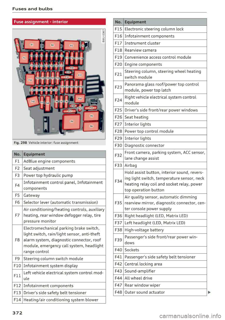
Fuse ass ignment - interior
ij
::, CX) ID
F ig. 298 Vehicle interior: fuse assignment
No. Equipment
Fl Ad Blue engine components
F2 Seat adjustment
F3 Power top hydraulic pump
F4 Infotainment control panel,
Infotainment
components
FS Gateway
F6 Selector lever (automat ic transm iss ion)
Air conditioning/heating controls, auxiliary
F7 heating, rear window defogger relay, tire pressure monitor
Electromechan ical park ing brake switch,
light switch, rain/light sensor, anti-theft
F8 alarm system,
diagnostic connector, roof
module, emergency call system, head light
range control
F9 Steering col umn sw itch module
FlO Infotainment system display
Fll Left vehicle electrica
l system control mod-
ule
F12 Infotainment components
F13 Driver's side safety belt tensioner
F 14 Heat ing/a ir condit ion ing system blower
372
No . Equipment
FlS Electronic
steering column lock
F16 Infotainment components
Fl7 Instrument cluster
Fl8 Rearview camera
Fl9 Convenience access control module
F20 Engine components
F21 Steering column, steering wheel heating
switch module
F23 Panorama glass
roof/power top control
module, power top latch
F24 R
ight vehicle electrical system control
module
F2S Driver
's side front/rear power windows
F26 Seat heating
F27 Interior
lights
F28 Power top control module
F29 Interior lights
F30 Diagnostic connector
F32 Front camera, parking
system, ACC sensor,
lane change assist
F33 Airbag
Hold assist button, interior sound, revers-
F34 i
ng light sw itch, temperature sensor, neck
heating relay coil and socket relay, power
top operation button
Air quality sensor, automatic dimming
F3S rearview
mirror, diagnostic connector, cen-
ter console power supply
F36 Right
headlight (LED, Matrix LED)
F37 Left headlight (LED, Matrix LED)
F38 High-voltage battery
F39 Passenger
's side front/rear power w in-
dows
F40 Sockets
F41 Passenger's sid e safe ty be lt tens ioner
F42 Central locking area
F43 Sound-amplifier
F44 All wheel drive
F47 Rear window wiper
F48 Outer sound actuator
Page 375 of 404
LL co .... N
" N .... 0 N > co
No. Equipment
F49 Clutch sensor (relay 1+2),
high-voltage
battery, power electronics
F52 Control module for suspension control
F53 Rear window defogger
The power seats* are protected via
circuit break
ers
that automatically switch on after a few sec
onds after the overload has been reduced.
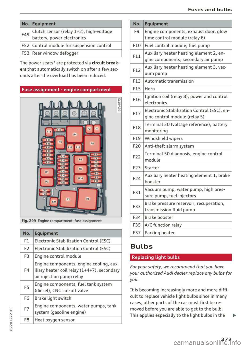
Fuse assignment -engine compartment
Fig. 299 Engine compartme nt: fuse assignment
No. Equipment
Fl Electronic Stabilization Control (ESC)
F2 Electronic Stabilization Control (ESC)
F3 Engine control module
Eng ine components, engine cooling, aux-
F4 iliary heater co il relay (1+4+7), secondary
air inject ion pump relay
FS Engine components, fue
l tank system
(diesel), CNG cut-off va lve
F6 Brake light switch
F7 Eng
ine components, water pumps, tank
system (gasoline engine)
FB Heat oxygen sensor
Fuses and bulbs
No. Equipment
F9 Engine
components, exhaust door, glow
time control module (relay 6)
F lO Fuel control module, fuel pump
F ll Auxiliary
heater heating element 2, en-
gine components, secondary air pump
F12 Auxiliary
heater heating element 3, vac-
uum pump
F13 Automat ic transmission
F lS Horn
F16 Ign
it ion coil (relay 8), power and control
electronics
F17 E
lectroni c Stabilization Control (ESC), en-
gine control module (relay S)
F18 Terminal
30 (voltage reference), battery
monitoring
Fl9 Windshield wipers
F20 Anti-theft alarm system
F22 Terminal
SO diagnos is, engine control
module
F23 Starter
F24 Auxiliary
heater heating element 1, brake
booster
F 31 Vacuum pump, water pump, high pres-
sure pump, fuel injectors
F33 Brake
pressure reservoir, recuperation,
transmission fluid pump
F34 Brake booster
F 35 A/C function
relay
F37 Parking heater
Bulbs
Replacing light bulbs
For your safety, we recommend that you have
your authorized Audi dealer replace any bulbs for
you.
It is becom ing increasingly more and more diffi
cu lt to replace vehicle light bulbs since in many
cases, other parts of the car must first be re
moved before you are ab le to get to the bulb.
This applies especially to the light bulbs in the
373
Page 390 of 404
Index
Audi pre sense . . . . . . . . . . . . . . . . . . . . . . . 130
Messages . . . . . . . . . . . . . . . . . . . . . . 130, 133
Aud i Service Repair Manuals and Literature 383
Audi side assist . . . . . . . . . . . . . . . . . . . . . . . 136
Cleaning the sensors . . . . . . . . . . . . . . . . . 355
Messages . . . . . . . . . . . . . . . . . . . . . . . . . . 140
Rear cross-traffic assist . . . . . . . . . . . . . . . 139
Audi smartphone interface . . . . . . . . . 241, 245
Aud i virtual cockp it
refer to Instrument cluster . . . . . . . . . . . . . 10
AUTO
Automatic climate control system . . . . . . .
69
Automatic headlights . . . . . . . . . . . . . . . . . 49
Auto Lock (centr al locking system) . . . . . . . . 31
Automatic belt retractor . . . . . . . . . . . . . . . 264
Automatic climate control system
refer to Climate control system
(automatic) . . . . . . . . . . . . . . . . . . . . . .
68, 69
Automatic power top
refer to Power top . . . . . . . . . . . . . . . . . . . . 42
Automatic transmission . . . . . . . . . . . . . . . . . 83
Driving tips . . . . . . . . . . . . . . . . . . . . . . . . . . 86
Emergency mode . . . . . . . . . . . . . . . . . . . . . 89
Hill descent control . . . . . . . . . . . . . . . . . . . 87
Kick -down . . . . . . . . . . . . . . . . . . . . . . . . . . .
88
Launch control program . . . . . . . . . . . . . . . 89
Malfunction . . . . . . . . . . . . . . . . . . . . . . . . . 84
Manual shift ing (tiptronic mode) . . . . . . . . 88
Selector lever . . . . . . . . . . . . . . . . . . . . . . . . 86
Selector lever emergency re lease . . . . . . . . 90
Selector lever lock . . . . . . . . . . . . . . . . . . . . 84
Selector lever positions . . . . . . . . . . . . . . . . 84
Shift padd les . . . . . . . . . . . . . . . . . . . . . . . . 88
Automatic wipe/wash system . . . . . . . . . . . . 55
Auto Safety Hotline . . . . . . . . . . . . . . . . . . .
258
Auxiliary climate contro l . . . . . . . . . . . . . . . 116
AUX input . . . . . . . . . . . . . . . . . . . . . . . . . . . 230
Average consumption ........... .... . 17, 18
Average speed . . . . . . . . . . . . . . . . . . . . . 17, 18
B
BACK button . . . . . . . . . . . . . . . . . . . . . . . . . 154
Bag hooks . . . . . . . . . . . . . . . . . . . . . . . . .
63, 65
Balance (sound) . . . . . . . . . . . . . . . . . . . . . . 247
Bass (sound) . . . . . . . . . . . . . . . . . . . . . . . . . 247
388
Battery
In the key . . . . . . . . . . . . . . . . . . . . . . . . . . .
32
also refer to High-voltage battery . . . . . . . 92
also refer to Vehicle battery . . . . . . . . . . . 326
Before driv ing . . . . . . . . . . . . . . . . . . . . . . . . 249
Belt tensioners . . . . . . . . . . . . . . . . . . . . . . . 267
Blended gasoline . . . . . . . . . . . . . . . . . . . . . 314
Blower
Automat ic climate control system . . . . . . .
70
Bluetooth
Audio player . . . . . . . . . . . . . . . . . . . . . . . .
226
Connecting a cell phone . . . . . . . . . . . . . . 177
Settings . . . . . . . . . . . . . . . . . . . . . . . . . . . 246
Boost . . . . . . . . . . . . . . . . . . . . . . . . . . . . . . . . 19
Booster seats . . . . . . . . . . . . . . . . . . . . . . . . 304
Boost pressure indicator . . . . . . . . . . . . . . . . 19
Brakes . . . . . . . . . . . . . . . . . . . . . . . . . . . . . . 150
Brake assist . . . . . . . . . . . . . . . . . . . . . . . . 148
Brake fluid . . . . . . . . . . . . . . . . . . . . . . . . . 326
Electromechanical parking brake . . . . . . . . 81
Emergency braking function . . . . . . . . . . . . 82
New brake pads . . . . . . . . . . . . . . . . . . . . . 150
Break-in security feature . . . . . . . . . . . . . . . . 36
Breaking in
New brake pads . . . . . . . . . . . . . . . . . . . . .
150
New engine . . . . . . . . . . . . . . . . . . . . . . . . . 72
New tires . .... .. .. .. ............. .. 337
Browser
refer to Media center . . . . . . . . . . . . . . . . . 233
Bulbs . . . . . . . . . . . . . . . . . . . . . . . . . . . . . . . 373
Buttons
Control panel (MMI) . . . . . . . . . . . . . . . . .
154
Multifunction steering wheel . . . . . . . . 13, 16
Programming (multifunction steering
wheel) . . . . . . . . . . . . . . . . . . . . . . . . . . . . . . 15
Switching the Infotainment system display
on/off . . . . . . . . . . . . . . . . . . . . . . . . . . . . .
155
C
Cable (USB adapter/AUX connector cable) 229
California Proposition 65 Warning . . . . . . . 319
Battery specific . . . . . . . . . . . . . . . . . . . . . 327
Call list . . . . . . . . . . . . . . . . . . . . . . . . . . . . . 180
Call options . . . . . . . . . . . . . . . . . . . . . . . . . . 188
Page 397 of 404
u. 00 .-< N l' N .-< 0 N > 00
Online map update ................... . 214
Onl ine media . . . . . . . . . . . . . . . . . . . . . . . . . 228
Online services
refer to Audi connect (Infotainment) . . . . 190
Opening ..... .. ................ ..... .. 31
Doors . . . . . . . . . . . . . . . . . . . . . . . . . . . 33, 34
Fu el filler door ................ ..... . 315
Hood .. .. .. .. ............... .. .. .. . 320
Luggage compartment lid . . . . . . . . . . . . . . 37
Panorama glass roof . . . . . . . . . . . . . . . . . . 40
Power top . . . . . . . . . . . . . . . . . . . . . . . . . . . 42
Windows . . . . . . . . . . . . . . . . . . . . . . . . . . . 39
Opening/closing
refer to Unlocking/locking ..... .. 31, 33, 34
Operating Multifunction steering wheel . . . . . . . . 13, 16
Multi Media Interface . . . . . . . . . . . . . . . . 155
Voice recognition system . . . . . . . . . . . . . 170
Opt ions menu .. ............. .. 14, 156 , 160
Outside temperature display . . . . . . . . . . . . . 10
Overview (Cockpit) 8
p
Paint damage . . . . . . . . . . . . . . . . . . . . . . . . 356
Paint number . . . . . . . . . . . . . . . . . . . . . . . . 381
Panorama glass roof. . . . . . . . . . . . . . . . . . . . 40
also refer to Convenience opening/closing 40
Parental control
DVD ............................... 235
Parking aid . . . . . . . . . . . . . . . . . . . . . . . . . . 143
Adjusting . . . . . . . . . . . . . . . . . . . . . . . . . . 147
C leaning sensors/camera . . . . . . . . . . . . . 355
Malfunction . . . . . . . . . . . . . . . . . . . . . . . . 147
Rearview camera . . . . . . . . . . . . . . . . . . . . 145
Parking brake
refer to Electromechanical parking brake . 81
Parking lights . . . . . . . . . . . . . . . . . . . . . . . . . 49
Parking (automatic transmission) . . . . . . . . . 86
Parts replacement . . . . . . . . . . . . . . . . . . . . 385
Pass -through . . . . . . . . . . . . . . . . . . . . . . . . . 66
PASSENGER AIR BAG OFF light . . . . . . . . . . 281
Pause (audio/video file) . . . . . . . . . . . . . . . . 232
Pedals . . . . . . . . . . . . . . . . . . . . . . . . . . . . . . 254
Performance/torque display
refer to Sport displays . . . . . . . . . . . . . . . . . 20
Personal route assistance . . . . . . . . . . . . . . 206
Index
Phone book
refer to Contacts
186
Physical principles of a frontal col lision . . . 261
Picture format (video) . . . . . . . . . . . . . . . . . 235
Playback (media) . . . . . . . . . . . . . . . . . . . . . 232
Playlist . . . . . . . . . . . . . . . . . . . . . . . . . . . . . 234
Plug-in-Hybrid-Drive High-voltage battery . . . . . . . . . . . . . . . . . . 93
Plug-in hybrid drive . . . . . . . . . . . . . . . . . . . . 92
12 volt vehicle battery . . . . . . . . . . . . . . . . 102
Auxiliary climate control . . . . . . . . . . . . . . 116
Boost . . . . . . . . . . . . . . . . . . . . . . . . . . . . . . 99
Charging . . . . . . . . . . . . . . . . . . . . . . . . . . . 104
Charging clip . . . . . . . . . . . . . . . . . . . . . . . 108
Charging dock . . . . . . . . . . . . . . . . . . . . . . 108
Charging system PIN . . . . . . . . . . . . . . . . . 115
Charging the high-voltage battery . . . . . . 106
Charging time . . . . . . . . . . . . . . . . . . . . . . 114
Cleaning the charging system ........ .. 117
Climate control . . . . . . . . . . . . . . . . . . . . . 116
Coasting . . . . . . . . . . . . . . . . . . . . . . . . . . . . 99
Coo lant . . . . . . . . . . . . . . . . . . . . . . . . . . . . 102
Driving . . . . . . . . . . . . . . . . . . . . . . . . . . . . . 94
E-max (power availability) . . . . . . . . . . . . . 100
Efficient driving . . . . . . . . . . . . . . . . . . . . . . 99
Ending drive ready mode . . . . . . . . . . . . . . . 94
Energy flow display . . . . . . . . . . . . . . . . . . 100
Establishing drive ready mode . . . . . . . . . . 94
EV mode/hybrid mode . . . . . . . . . . . . . . . . . 98
High-vo ltage battery .............. 92, 115
High-vo ltage system . . . . . . . . . . . . . . . . . . 92
Indicator lights . . . . . . . . . . . . . . . . . . . . . . 96
Inserting the fuel pump nozzle . . . . . . . . . 103
Introduction . . . . . . . . . . . . . . . . . . . . . . . . . 92
Jump start . . . . . . . . . . . . . . . . . . . . . . . . . 102
Jump starting . . . . . . . . . . . . . . . . . . . . . . . 102
Power meter . . . . . . . . . . . . . . . . . . . . . . . . . 95
Range and statistics . . . . . . . . . . . . . . . . . . . 97
Range disp lay . . . . . . . . . . . . . . . . . . . . . . . . 97
Recuperation . . . . . . . . . . . . . . . . . . . . . . . . 99
Refueling . . . . . . . . . . . . . . . . . . . . . . . . . . 103
Setting the modes . . . . . . . . . . . . . . . . . . . . 98
Starting the vehicle . . . . . . . . . . . . . . . . . . . 94
Status dis plays . . . . . . . . . . . . . . . . . . . . . . 112
Switching the ignition on/off . . . . . . . . . . . 94
Tachometer . . . . . . . . . . . . . . . . . . . . . . . . . 95
Tire mobility kit . . . . . . . . . . . . . . . . . . . . . 101
Vehicle sound . . . . . . . . . . . . . . . . . . . . . . . . 94
395