AUDI A4 1995 B5 / 1.G 01W Transmission Pinion Shaft Workshop Manual
Manufacturer: AUDI, Model Year: 1995,
Model line: A4,
Model: AUDI A4 1995 B5 / 1.G
Pages: 26, PDF Size: 0.62 MB
AUDI A4 1995 B5 / 1.G 01W Transmission Pinion Shaft Workshop Manual
A4 1995 B5 / 1.G
AUDI
AUDI
https://www.carmanualsonline.info/img/6/1275/w960_1275-0.png
AUDI A4 1995 B5 / 1.G 01W Transmission Pinion Shaft Workshop Manual
Trending: length, ad blue, ECU, differential, technical data
Page 1 of 26
35-21
Pinion shaft, disassembling
and assembling
Special tools and equipment
204B installation tool for crankshaft seal
VW401 thrust plate
VW402 thrust plate
VW407 punch
VW408A punch
VW412 punch
VW415A tube
VW421 tube
VW455 thrust tube
VW519 sleeve
Pa
ge 1 of 26 Pinion shaft, disassemblin
g and assemblin
g
11/19/2002 htt
p://127.0.0.1:8080/audi/servlet/Dis
play?action=Goto&t
yp
e=re
pair&id=AUDI.B5.TM01.35.3
Page 2 of 26
VW771 slide hammer-complete set
Pa
ge 2 of 26 Pinion shaft, disassemblin
g and assemblin
g
11/19/2002 htt
p://127.0.0.1:8080/audi/servlet/Dis
play?action=Goto&t
yp
e=re
pair&id=AUDI.B5.TM01.35.3
Page 3 of 26
35-22
2010 sleeve
3062 thrust pad
3118 sleeve
3128 bushing puller
Kukko 17/2 separating tool
Kukko 21/1 extractor
Pa
ge 3 of 26 Pinion shaft, disassemblin
g and assemblin
g
11/19/2002 htt
p://127.0.0.1:8080/audi/servlet/Dis
play?action=Goto&t
yp
e=re
pair&id=AUDI.B5.TM01.35.3
Page 4 of 26
35-23
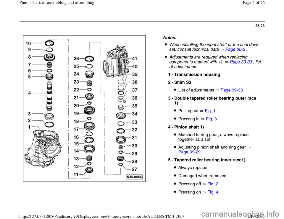
Notes:
When installing the input shaft or the final drive
set, consult technical data Page 00
-3 .
Adjustments are required when replacing
components marked with 1): Page 39
-33
, list
of adjustments
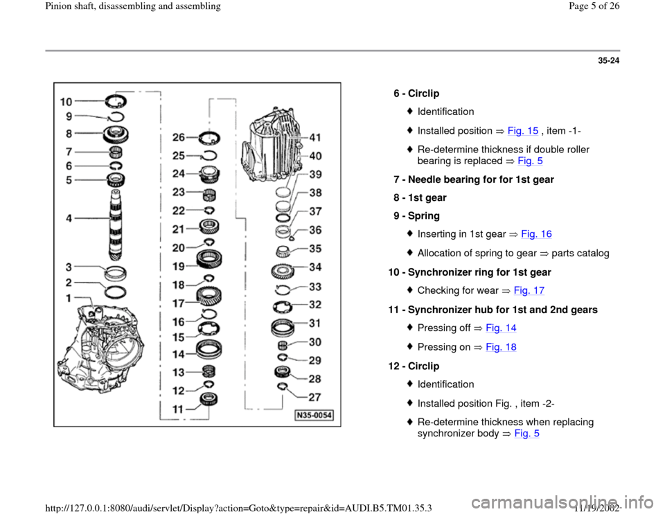
1 -
Transmission housing
2 -
Shim S3
List of adjustments Page 39
-33
3 -
Double tapered roller bearing outer race
1)
Pulling out Fig. 1Pressing in Fig. 3
4 -
Pinion shaft 1)
Matched to ring gear; always replace
together as a set Adjusting pinion shaft and ring gear
Page 39
-29
5 -
Tapered roller bearing inner race1)
Always replaceDamaged when removedPressing off Fig. 2Pressing on Fig. 4
Pa
ge 4 of 26 Pinion shaft, disassemblin
g and assemblin
g
11/19/2002 htt
p://127.0.0.1:8080/audi/servlet/Dis
play?action=Goto&t
yp
e=re
pair&id=AUDI.B5.TM01.35.3
Page 5 of 26
35-24
6 -
Circlip
IdentificationInstalled position Fig. 15
, item -1-
Re-determine thickness if double roller
bearing is replaced Fig. 5
7 -
Needle bearing for for 1st gear
8 -
1st gear
9 -
Spring
Inserting in 1st gear Fig. 16Allocation of spring to gear parts catalog
10 -
Synchronizer ring for 1st gear
Checking for wear Fig. 17
11 -
Synchronizer hub for 1st and 2nd gears
Pressing off Fig. 14Pressing on Fig. 18
12 -
Circlip
IdentificationInstalled position Fig. , item -2-Re-determine thickness when replacing
synchronizer body Fig. 5
Pa
ge 5 of 26 Pinion shaft, disassemblin
g and assemblin
g
11/19/2002 htt
p://127.0.0.1:8080/audi/servlet/Dis
play?action=Goto&t
yp
e=re
pair&id=AUDI.B5.TM01.35.3
Page 6 of 26
35-25
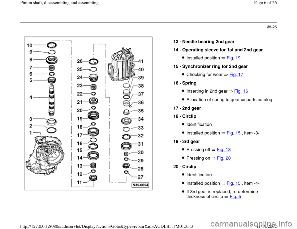
13 -
Needle bearing 2nd gear
14 -
Operating sleeve for 1st and 2nd gear
Installed position Fig. 19
15 -
Synchronizer ring for 2nd gear
Checking for wear Fig. 17
16 -
Spring
Inserting in 2nd gear Fig. 16Allocation of spring to gear parts catalog
17 -
2nd gear
18 -
Circlip
IdentificationInstalled position Fig. 15
, item -3-
19 -
3rd gear
Pressing off Fig. 13Pressing on Fig. 20
20 -
Circlip
IdentificationInstalled position Fig. 15
, item -4-
If 3rd gear is replaced, re-determine
thickness of circlip Fig. 5
Pa
ge 6 of 26 Pinion shaft, disassemblin
g and assemblin
g
11/19/2002 htt
p://127.0.0.1:8080/audi/servlet/Dis
play?action=Goto&t
yp
e=re
pair&id=AUDI.B5.TM01.35.3
Page 7 of 26
35-26
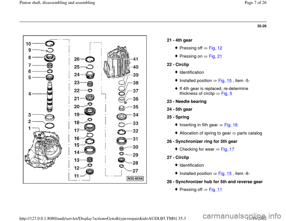
21 -
4th gear
Pressing off Fig. 12Pressing on Fig. 21
22 -
Circlip
IdentificationInstalled position Fig. 15
, item -5-
If 4th gear is replaced, re-determine
thickness of circlip Fig. 5
23 -
Needle bearing
24 -
5th gear
25 -
Spring
Inserting in 5th gear Fig. 16Allocation of spring to gear parts catalog
26 -
Synchronizer ring for 5th gear
Checking for wear Fig. 17
27 -
Circlip
IdentificationInstalled position Fig. 15
, item -6-
28 -
Synchronizer hub for 5th and reverse gear
Pressing off Fig. 11
Pa
ge 7 of 26 Pinion shaft, disassemblin
g and assemblin
g
11/19/2002 htt
p://127.0.0.1:8080/audi/servlet/Dis
play?action=Goto&t
yp
e=re
pair&id=AUDI.B5.TM01.35.3
Page 8 of 26
Pressing on Fig. 22
Pa
ge 8 of 26 Pinion shaft, disassemblin
g and assemblin
g
11/19/2002 htt
p://127.0.0.1:8080/audi/servlet/Dis
play?action=Goto&t
yp
e=re
pair&id=AUDI.B5.TM01.35.3
Page 9 of 26
35-27
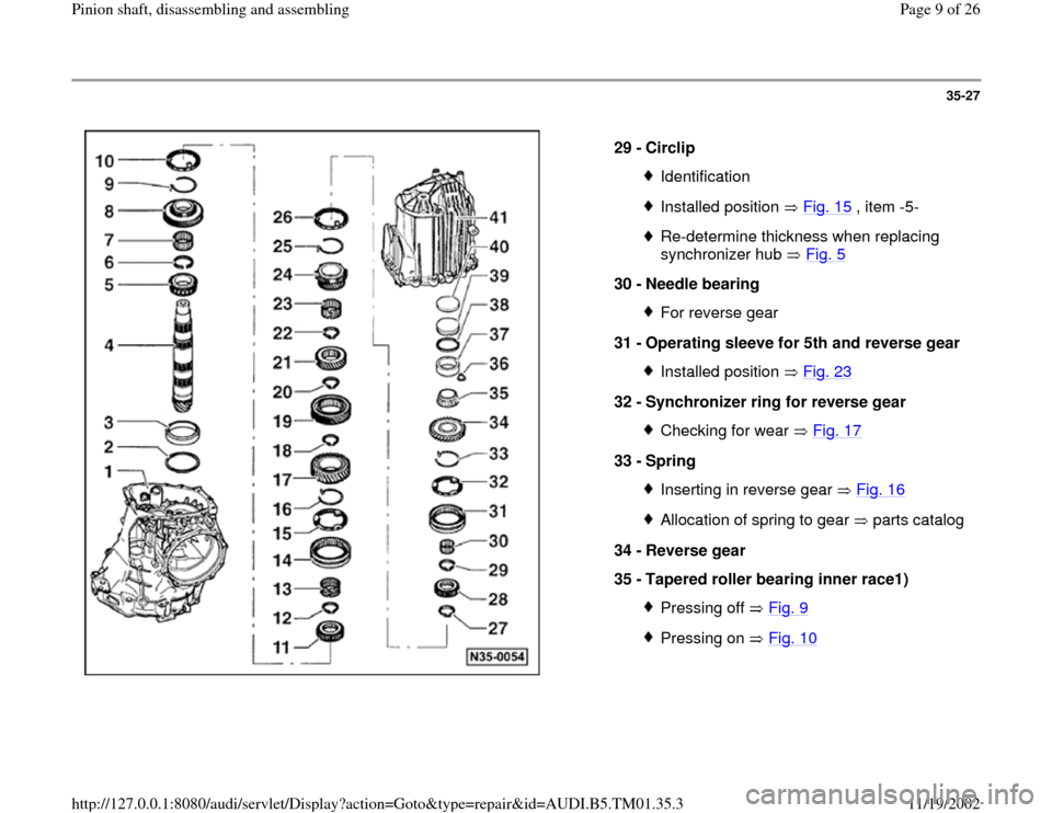
29 -
Circlip
IdentificationInstalled position Fig. 15
, item -5-
Re-determine thickness when replacing
synchronizer hub Fig. 5
30 -
Needle bearing
For reverse gear
31 -
Operating sleeve for 5th and reverse gear Installed position Fig. 23
32 -
Synchronizer ring for reverse gear
Checking for wear Fig. 17
33 -
Spring
Inserting in reverse gear Fig. 16Allocation of spring to gear parts catalog
34 -
Reverse gear
35 -
Tapered roller bearing inner race1)
Pressing off Fig. 9Pressing on Fig. 10
Pa
ge 9 of 26 Pinion shaft, disassemblin
g and assemblin
g
11/19/2002 htt
p://127.0.0.1:8080/audi/servlet/Dis
play?action=Goto&t
yp
e=re
pair&id=AUDI.B5.TM01.35.3
Page 10 of 26
35-28
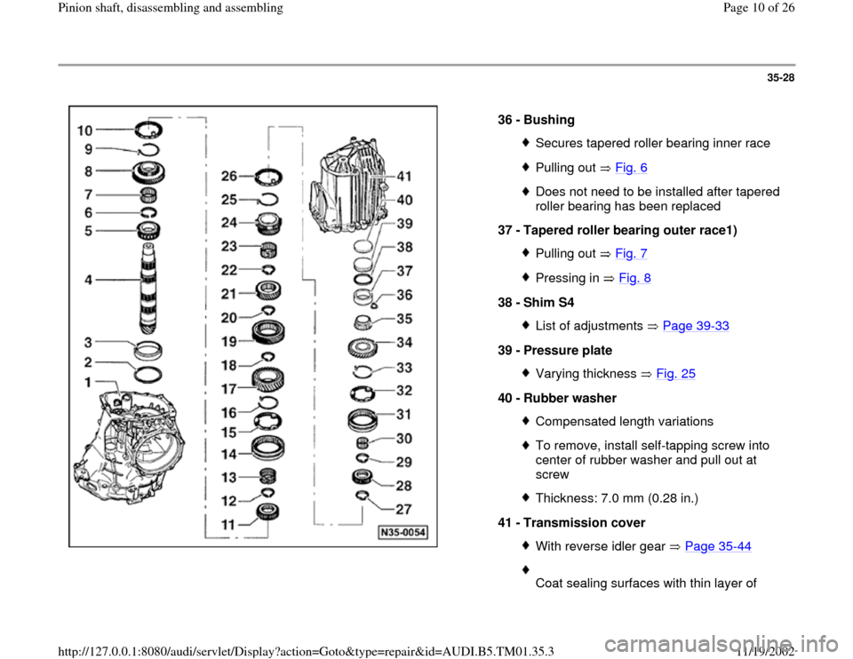
36 -
Bushing
Secures tapered roller bearing inner racePulling out Fig. 6Does not need to be installed after tapered
roller bearing has been replaced
37 -
Tapered roller bearing outer race1) Pulling out Fig. 7Pressing in Fig. 8
38 -
Shim S4
List of adjustments Page 39
-33
39 -
Pressure plate
Varying thickness Fig. 25
40 -
Rubber washer
Compensated length variationsTo remove, install self-tapping screw into
center of rubber washer and pull out at
screw Thickness: 7.0 mm (0.28 in.)
41 -
Transmission cover With reverse idler gear Page 35
-44
Coat sealing surfaces with thin layer of
Pa
ge 10 of 26 Pinion shaft, disassemblin
g and assemblin
g
11/19/2002 htt
p://127.0.0.1:8080/audi/servlet/Dis
play?action=Goto&t
yp
e=re
pair&id=AUDI.B5.TM01.35.3
Trending: ECU, ad blue, differential, technical data, length
