oil AUDI A4 1995 B5 / 1.G AFC Engine Cylinder Block Crankshaft And Flywheel Component Assembly Manual
[x] Cancel search | Manufacturer: AUDI, Model Year: 1995, Model line: A4, Model: AUDI A4 1995 B5 / 1.GPages: 32, PDF Size: 0.44 MB
Page 1 of 32
13-6
Cylinder block, crankshaft and
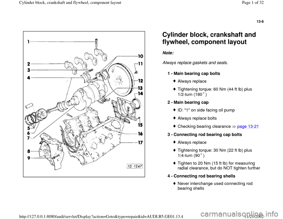
flywheel, component layout Note:
Always replace gaskets and seals.
1 -
Main bearing cap bolts
Always replaceTightening torque: 60 Nm (44 ft lb) plus
1/2-turn (180 )
2 -
Main bearing cap
ID: "1" on side facing oil pumpAlways replace boltsChecking bearing clearance page 13
-21
3 -
Connecting rod bearing cap bolts
Always replaceTightening torque: 30 Nm (22 ft lb) plus
1/4-turn (90 ) Tighten to 20 Nm (15 ft lb) for measuring
radial clearance, but do NOT tighten further
4 -
Connecting rod bearing shells Never interchange used connecting rod
bearing shells
Pa
ge 1 of 32 C
ylinder block, crankshaft and fl
ywheel, com
ponent la
yout
11/21/2002 htt
p://127.0.0.1:8080/audi/servlet/Dis
play?action=Goto&t
yp
e=re
pair&id=AUDI.B5.GE01.13.4
Page 3 of 32
13-7
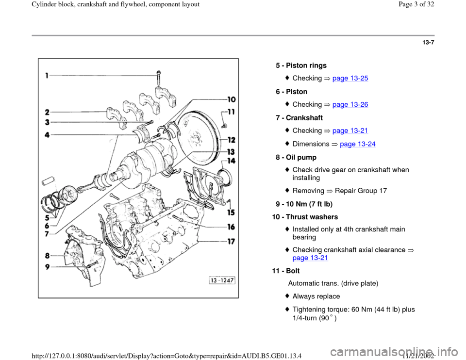
5 -
Piston rings
Checking page 13
-25
6 -
Piston
Checking page 13
-26
7 -
Crankshaft
Checking page 13
-21
Dimensions page 13
-24
8 -
Oil pump
Check drive gear on crankshaft when
installing Removing Repair Group 17
9 -
10 Nm (7 ft lb)
10 -
Thrust washers
Installed only at 4th crankshaft main
bearing Checking crankshaft axial clearance
page 13
-21
11 -
Bolt
Automatic trans. (drive plate)
Always replaceTightening torque: 60 Nm (44 ft lb) plus
1/4-turn (90 )
Pa
ge 3 of 32 C
ylinder block, crankshaft and fl
ywheel, com
ponent la
yout
11/21/2002 htt
p://127.0.0.1:8080/audi/servlet/Dis
play?action=Goto&t
yp
e=re
pair&id=AUDI.B5.GE01.13.4
Page 14 of 32
13-14
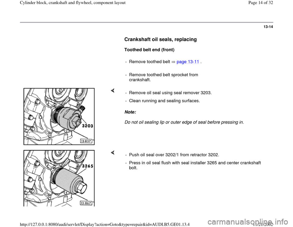
Crankshaft oil seals, replacing
Toothed belt end (front)
- Remove toothed belt page 13
-11
.
- Remove toothed belt sprocket from
crankshaft.
Note:
Do not oil sealing lip or outer edge of seal before pressing in. - Remove oil seal using seal remover 3203.
- Clean running and sealing surfaces.
- Push oil seal over 3202/1 from retractor 3202.
- Press in oil seal flush with seal installer 3265 and center crankshaft
bolt.
Pa
ge 14 of 32 C
ylinder block, crankshaft and fl
ywheel, com
ponent la
yout
11/21/2002 htt
p://127.0.0.1:8080/audi/servlet/Dis
play?action=Goto&t
yp
e=re
pair&id=AUDI.B5.GE01.13.4
Page 15 of 32
13-15
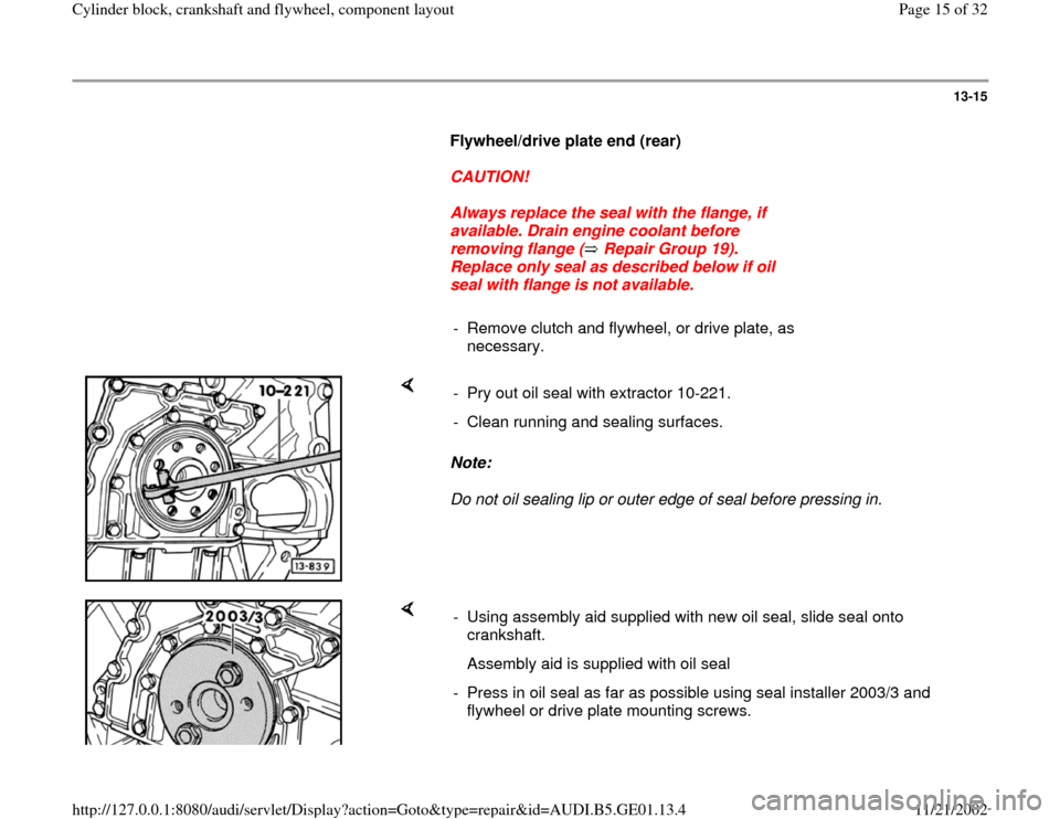
Flywheel/drive plate end (rear)
CAUTION!
Always replace the seal with the flange, if
available. Drain engine coolant before
removing flange ( Repair Group 19).
Replace only seal as described below if oil
seal with flange is not available.
- Remove clutch and flywheel, or drive plate, as
necessary.
Note:
Do not oil sealing lip or outer edge of seal before pressing in. - Pry out oil seal with extractor 10-221.
- Clean running and sealing surfaces.
- Using assembly aid supplied with new oil seal, slide seal onto
crankshaft.
Assembly aid is supplied with oil seal
- Press in oil seal as far as possible using seal installer 2003/3 and
flywheel or drive plate mounting screws.
Pa
ge 15 of 32 C
ylinder block, crankshaft and fl
ywheel, com
ponent la
yout
11/21/2002 htt
p://127.0.0.1:8080/audi/servlet/Dis
play?action=Goto&t
yp
e=re
pair&id=AUDI.B5.GE01.13.4
Page 21 of 32
13-21
Crankshaft axial and radial clearance,
checking
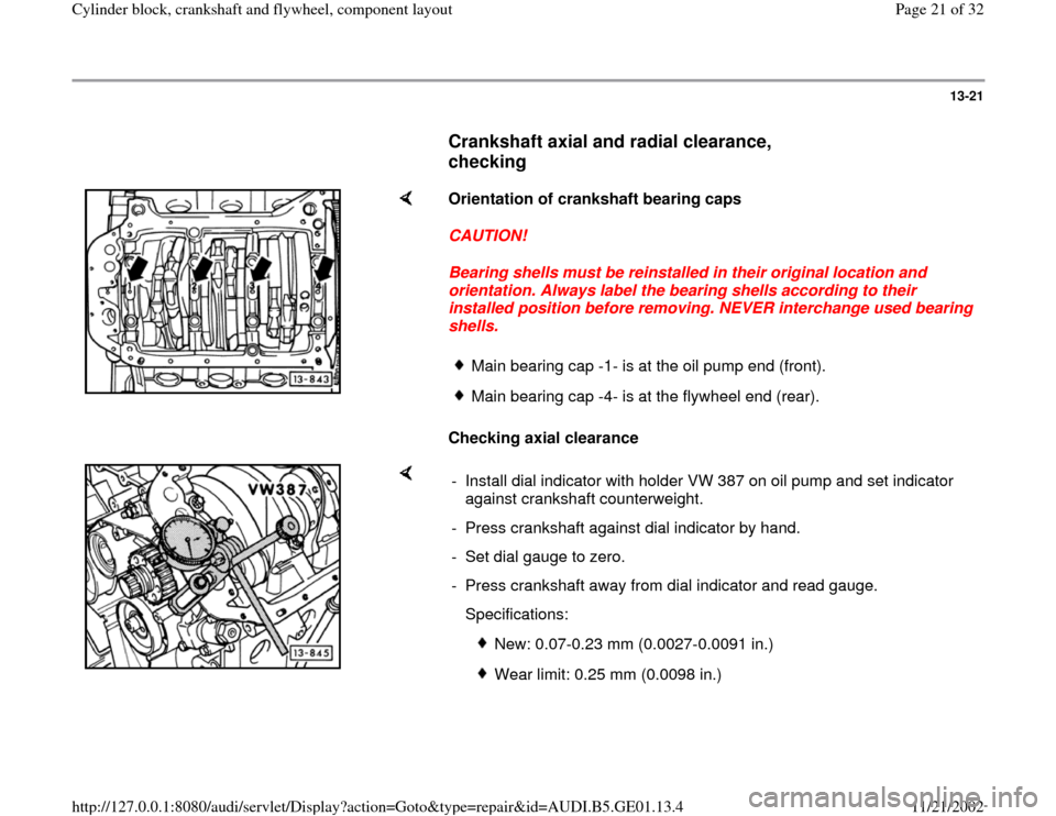
Orientation of crankshaft bearing caps
CAUTION!
Bearing shells must be reinstalled in their original location and
orientation. Always label the bearing shells according to their
installed position before removing. NEVER interchange used bearing
shells.
Checking axial clearance
Main bearing cap -1- is at the oil pump end (front).Main bearing cap -4- is at the flywheel end (rear).
- Install dial indicator with holder VW 387 on oil pump and set indicator
against crankshaft counterweight.
- Press crankshaft against dial indicator by hand.
- Set dial gauge to zero.
- Press crankshaft away from dial indicator and read gauge.
Specifications:
New: 0.07-0.23 mm (0.0027-0.0091 in.)
Wear limit: 0.25 mm (0.0098 in.)
Pa
ge 21 of 32 C
ylinder block, crankshaft and fl
ywheel, com
ponent la
yout
11/21/2002 htt
p://127.0.0.1:8080/audi/servlet/Dis
play?action=Goto&t
yp
e=re
pair&id=AUDI.B5.GE01.13.4
Page 25 of 32
13-25
Pistons and piston rings, checking and
installing
Note:
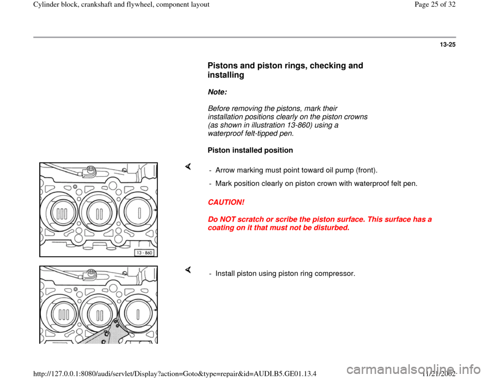
Before removing the pistons, mark their
installation positions clearly on the piston crowns
(as shown in illustration 13-860) using a
waterproof felt-tipped pen.
Piston installed position
CAUTION!
Do NOT scratch or scribe the piston surface. This surface has a
coating on it that must not be disturbed. - Arrow marking must point toward oil pump (front).
- Mark position clearly on piston crown with waterproof felt pen.
- Install piston using piston ring compressor.
Pa
ge 25 of 32 C
ylinder block, crankshaft and fl
ywheel, com
ponent la
yout
11/21/2002 htt
p://127.0.0.1:8080/audi/servlet/Dis
play?action=Goto&t
yp
e=re
pair&id=AUDI.B5.GE01.13.4