instrument cluster AUDI A4 1995 B5 / 1.G APB Engine Additional Signals Checking Workshop Manual
[x] Cancel search | Manufacturer: AUDI, Model Year: 1995, Model line: A4, Model: AUDI A4 1995 B5 / 1.GPages: 37, PDF Size: 0.14 MB
Page 1 of 37
24-179
Additional signals, checking
Engine speed (RPM) signal, checking
Note:
The engine speed signal is taken from terminal
37 on the Engine Control Module (ECM). The
signal is used for various functions including the
RPM display in the instrument cluster.
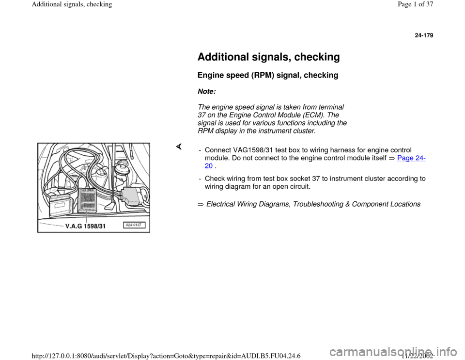
Electrical Wiring Diagrams, Troubleshooting & Component Locations - Connect VAG1598/31 test box to wiring harness for engine control
module. Do not connect to the engine control module itself Page 24
-
20
.
- Check wiring from test box socket 37 to instrument cluster according to
wiring diagram for an open circuit.
Pa
ge 1 of 37 Additional si
gnals, checkin
g
11/22/2002 htt
p://127.0.0.1:8080/audi/servlet/Dis
play?action=Goto&t
yp
e=re
pair&id=AUDI.B5.FU04.24.6
Page 3 of 37
24-181
Coolant temperature signal, checking
Notes:
The engine control module receives the coolant
temperature signal from the instrument cluster.
When the signal is received, the charge
pressure is reduced to prevent the engine from
overheating.
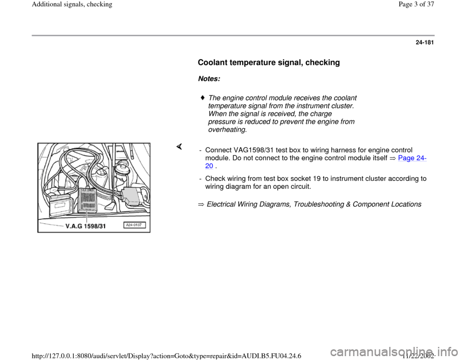
Electrical Wiring Diagrams, Troubleshooting & Component Locations - Connect VAG1598/31 test box to wiring harness for engine control
module. Do not connect to the engine control module itself Page 24
-
20
.
- Check wiring from test box socket 19 to instrument cluster according to
wiring diagram for an open circuit.
Pa
ge 3 of 37 Additional si
gnals, checkin
g
11/22/2002 htt
p://127.0.0.1:8080/audi/servlet/Dis
play?action=Goto&t
yp
e=re
pair&id=AUDI.B5.FU04.24.6
Page 4 of 37
24-182
Vehicle Speed Signal (VSS), checking
Notes:
The vehicle speed signal is generated by the
Vehicle Speed Sensor (VSS) -G68 (on the
transmission) and is processed in the
instrument cluster.
The processed signal goes to terminal 54 on
the engine control module and is used for Idle
Air Control (IAC) and for the damping of load
change jolts when changing gear.
- Start engine.
- Connect vehicle diagnostic, testing and
information system VAS 5051 or VAG1551 scan
tool and select engine electronics control
module by entering address word "01" Page 01
-9 .
- Select "Read measured value block" (function
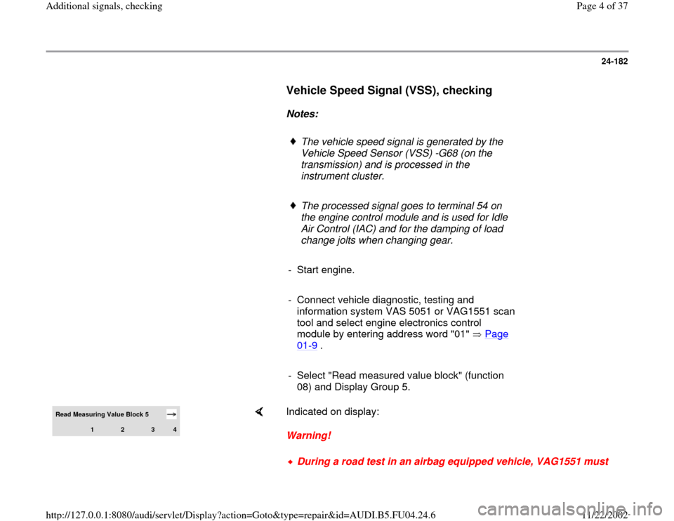
08) and Display Group 5. Read Measuring Value Block 5
1
2
3
4
Indicated on display:
Warning!
During a road test in an airbag equipped vehicle, VAG1551 must
Pa
ge 4 of 37 Additional si
gnals, checkin
g
11/22/2002 htt
p://127.0.0.1:8080/audi/servlet/Dis
play?action=Goto&t
yp
e=re
pair&id=AUDI.B5.FU04.24.6
Page 7 of 37
24-184
Fuel tank level signal, checking
Note:
The Engine Control Module (ECM) receives the
fuel tank level signal from the instrument
cluster.
The processed signal enters on terminal 30 the
Engine Control Module (ECM) and is used to
determine certain malfunctions (e.g.: misfire)
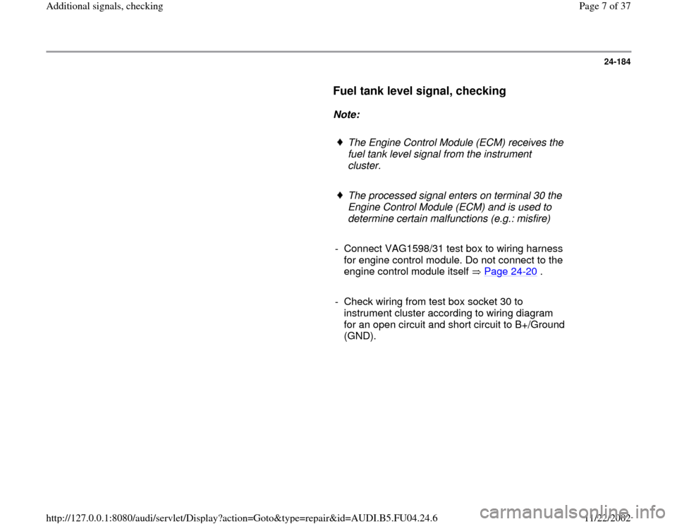
- Connect VAG1598/31 test box to wiring harness
for engine control module. Do not connect to the
engine control module itself Page 24
-20
.
- Check wiring from test box socket 30 to
instrument cluster according to wiring diagram
for an open circuit and short circuit to B+/Ground
(GND).
Pa
ge 7 of 37 Additional si
gnals, checkin
g
11/22/2002 htt
p://127.0.0.1:8080/audi/servlet/Dis
play?action=Goto&t
yp
e=re
pair&id=AUDI.B5.FU04.24.6
Page 29 of 37
24-203
Read measuring value block 125
1
2
3
4
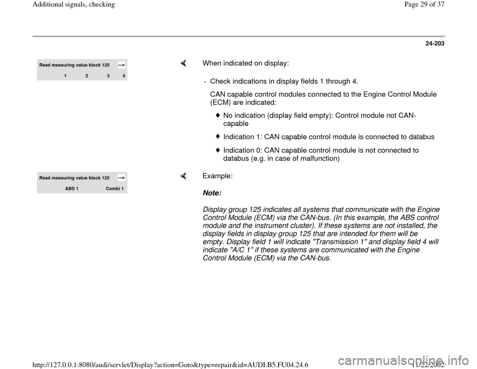
When indicated on display:
- Check indications in display fields 1 through 4.
CAN capable control modules connected to the Engine Control Module
(ECM) are indicated:
No indication (display field empty): Control module not CAN-
capable
Indication 1: CAN capable control module is connected to databus
Indication 0: CAN capable control module is not connected to
databus (e.g. in case of malfunction)
Read measuring value block 125
ABS 1
Combi 1
Example:
Note:
Display group 125 indicates all systems that communicate with the Engine
Control Module (ECM) via the CAN-bus. (In this example, the ABS control
module and the instrument cluster). If these systems are not installed, the
display fields in display group 125 that are intended for them will be
empty. Display field 1 will indicate "Transmission 1" and display field 4 will
indicate "A/C 1" if these systems are communicated with the Engine
Control Module (ECM) via the CAN-bus.
Pa
ge 29 of 37 Additional si
gnals, checkin
g
11/22/2002 htt
p://127.0.0.1:8080/audi/servlet/Dis
play?action=Goto&t
yp
e=re
pair&id=AUDI.B5.FU04.24.6