ignition AUDI A4 1995 B5 / 1.G APB Engine Electronic Engine Power Control Checking Workshop Manual
[x] Cancel search | Manufacturer: AUDI, Model Year: 1995, Model line: A4, Model: AUDI A4 1995 B5 / 1.GPages: 39, PDF Size: 0.16 MB
Page 2 of 39
24-140
With the engine is not running and the ignition
switched on, the ECM operates the throttle valve
positioner in exact accordance with the signals
from the accelerator position sensors. For
example, when the accelerator pedal is pressed
down half way, the throttle valve positioner opens
the throttle valve by an equivalent amount, i.e.
about half way.
When the engine is running (i.e. under load) the
ECM can open and close the throttle valve freely,
independently of the signals being sent by the
accelerator position sensors.
For example, the throttle valve might already be
fully open even though the accelerator pedal is
only pressed down half way. This has the
advantage of preventing throttling losses at the
throttle valve.
Pa
ge 2 of 39 Electronic En
gine Power Control
(EPC
), checkin
g
11/22/2002 htt
p://127.0.0.1:8080/audi/servlet/Dis
play?action=Goto&t
yp
e=re
pair&id=AUDI.B5.FU04.24.4
Page 4 of 39
24-142
Significance of electronic Engine Power
Control (EPC) warning light in
instrument cluster
"EPC" stands for Electronic Power Control and
refers to the electronic throttle control system
(Drive by wire).
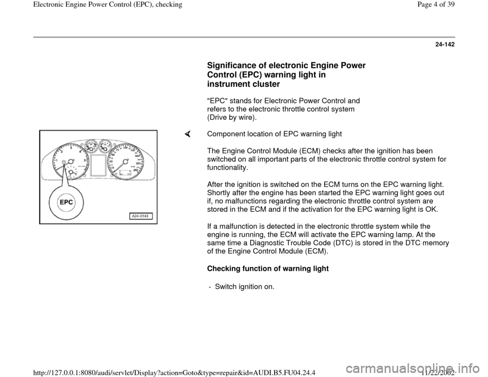
Component location of EPC warning light
The Engine Control Module (ECM) checks after the ignition has been
switched on all important parts of the electronic throttle control system for
functionality.
After the ignition is switched on the ECM turns on the EPC warning light.
Shortly after the engine has been started the EPC warning light goes out
if, no malfunctions regarding the electronic throttle control system are
stored in the ECM and if the activation for the EPC warning light is OK.
If a malfunction is detected in the electronic throttle system while the
engine is running, the ECM will activate the EPC warning lamp. At the
same time a Diagnostic Trouble Code (DTC) is stored in the DTC memory
of the Engine Control Module (ECM).
Checking function of warning light
- Switch ignition on.
Pa
ge 4 of 39 Electronic En
gine Power Control
(EPC
), checkin
g
11/22/2002 htt
p://127.0.0.1:8080/audi/servlet/Dis
play?action=Goto&t
yp
e=re
pair&id=AUDI.B5.FU04.24.4
Page 5 of 39
24-143
Specified value: The EPC warning light should
light up.
If the EPC warning light does not light up:
- Check wire from Engine Control Module (ECM)
to EPC warning light in instrument cluster as
follows: Cause:
EPC warning light is not activated or does
not light up because of an open circuit. Corrective action:
The EPC warning lamp should light up.
If the EPC warning lamp does not light up:
If the warning lamp and the voltage supply are OK: - Switch ignition off
- Connect VAG1598/31 test box . Do not connect engine control module.
- Bridge sockets 1 and 48 on test box
- Switch ignition on.
- Switch ignition off.
- Check whether lamp is burned out and test voltage supply to lamp wiring
diagram.
- Check for open circuit or short circuit in wiring between engine control module
and EPC warning lamp using wiring diagram. Determine and eliminate
Pa
ge 5 of 39 Electronic En
gine Power Control
(EPC
), checkin
g
11/22/2002 htt
p://127.0.0.1:8080/audi/servlet/Dis
play?action=Goto&t
yp
e=re
pair&id=AUDI.B5.FU04.24.4
Page 7 of 39
24-144
If EPC warning lamp remains lit for more than 3
seconds (i.e. continuously) when ignition is on,
proceed with test as follows:
- Start engine and allow it to run at idling speed.
Specified value: EPC warning lamp should go
out.
If the EPC warning lamp does not go out:
- Check DTC memory of Engine Control Module
(ECM).
If no DTCs are stored: Cause:
EPC warning light is activated via
short circuit to Ground (GND). Corrective action:
If the specification is not reached: - Switch ignition off
- Connect VAG1598/31 test box . Do not connect engine control module.
- Measure resistance between vehicle Ground and socket 48 on test box. Specified
value: infinity (because the wire should not have any direct Ground connection)
- Determine and eliminate short circuit to Ground in wiring between engine control
module and EPC warning lamp using wiring diagram.
If there are no malfunctions in the wiring to the EPC warning lamp:
Pa
ge 7 of 39 Electronic En
gine Power Control
(EPC
), checkin
g
11/22/2002 htt
p://127.0.0.1:8080/audi/servlet/Dis
play?action=Goto&t
yp
e=re
pair&id=AUDI.B5.FU04.24.4
Page 11 of 39
24-146
Throttle valve control module,
adaptation
The adaptation process enables the Engine
Control Module (ECM) to learn the different
positions of the throttle valve with the ignition
switched on and the engine not running. These
positions are stored in the control module. The
feedback signal indicating the position of the
throttle valve comes from the two angle sensors
for throttle valve drive.
If the Throttle Valve Control Module -J338 or the
ECM is removed and installed or replaced, or if
the voltage (power) supply to the ECM is
interrupted, an adaptation must be carried out.
Pa
ge 11 of 39 Electronic En
gine Power Control
(EPC
), checkin
g
11/22/2002 htt
p://127.0.0.1:8080/audi/servlet/Dis
play?action=Goto&t
yp
e=re
pair&id=AUDI.B5.FU04.24.4
Page 12 of 39
24-147
The learning process (adaptation process) is
carried out:
By selecting "Basic Setting" (function 04),
Display Group 060 with the ignition switched
on.
Automatically if the ignition is switched on for at
least 6 seconds without operating the starter or
depressing the accelerator, and if the Engine
Control Module (ECM) registers a "learning
requirement." (In this case, however, there is no
way of knowing whether the adaptation process
was successful or not.) The engine control
module will register a learning requirement if
the previously stored voltage readings from the
angle sensors do not correspond (within a
certain tolerance range) to the new voltage
readings.
Note:
The engine will not start during automatic
adaptation.
Pa
ge 12 of 39 Electronic En
gine Power Control
(EPC
), checkin
g
11/22/2002 htt
p://127.0.0.1:8080/audi/servlet/Dis
play?action=Goto&t
yp
e=re
pair&id=AUDI.B5.FU04.24.4
Page 13 of 39
24-148
Test conditions for adaptation of throttle
valve control module
No malfunctions stored in DTC memory
Page 01
-15
, check DTC memory
Engine not running, ignition switched on
Accelerator pedal not depressed
Coolant temperature between 5 C and
100 C (Display group 004, display field 3)
Intake air temperature less than 100 C
Voltage supply to engine control module
greater than 11Volt, Checking Page 28
-32
- Connect vehicle diagnostic, testing and
information system VAS 5051 or VAG1551 scan
tool and select engine electronics control
module by entering address word "01" Page
01
-9 . When doing this the ignition must be
switched on.
Pa
ge 13 of 39 Electronic En
gine Power Control
(EPC
), checkin
g
11/22/2002 htt
p://127.0.0.1:8080/audi/servlet/Dis
play?action=Goto&t
yp
e=re
pair&id=AUDI.B5.FU04.24.4
Page 16 of 39
24-151
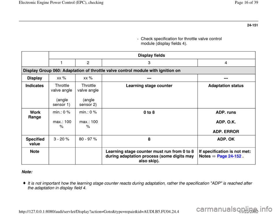
- Check specification for throttle valve control
module (display fields 4).
Display fields
1 2 3 4
Display Group 060: Adaptation of throttle valve control module with ignition on
Display xx % xx %
---
---
Indicates Throttle
valve angle
(angle
sensor 1) Throttle
valve angle
(angle
sensor 2) Learning stage counter
Adaptation status
Work
Range min.: 0 %
max.: 100
% min.: 0 %
max.: 100
% 0 to 8
ADP. runs
ADP. O.K.
ADP. ERROR
Specified
value 3 - 20 % 80 - 97 %
8
ADP. OK
Note
Learning stage counter must run from 0 to 8
during adaptation process (some digits may
also skip). If specification is not met:
Notes Page 24
-152
.
Note:
It is not important how the learning stage counter reacts during adaptation, rather the specification "ADP" is reached after
the adaptation in display field 4.
Pa
ge 16 of 39 Electronic En
gine Power Control
(EPC
), checkin
g
11/22/2002 htt
p://127.0.0.1:8080/audi/servlet/Dis
play?action=Goto&t
yp
e=re
pair&id=AUDI.B5.FU04.24.4
Page 19 of 39
start again automatically the next time the
ignition is switched on (for several seconds).
-
End engine basic setting by pressing the
button.
- Press buttons -0- and -6- to select "End Output"
function and confirm input with -Q- button.
Pa
ge 19 of 39 Electronic En
gine Power Control
(EPC
), checkin
g
11/22/2002 htt
p://127.0.0.1:8080/audi/servlet/Dis
play?action=Goto&t
yp
e=re
pair&id=AUDI.B5.FU04.24.4
Page 20 of 39
24-153
Angle sensor -1- for throttle drive
(power accelerator actuation) -G187-
and angle sensor -2- for throttle drive
(power accelerator actuation) -G188,
checking
The angle sensor -1- for throttle drive (power
accelerator actuation) -G187 and angle sensor -
2- for throttle drive (power accelerator actuation)
-G188 inform the engine control module of the
position of the throttle valve. Both angle sensors
are located in the throttle valve control module.
- Connect vehicle diagnostic, testing and
information system VAS 5051 or VAG1551 scan
tool and select engine electronics control
module by entering address word "01" Page
01
-9 . When doing this the ignition must be
switched on.
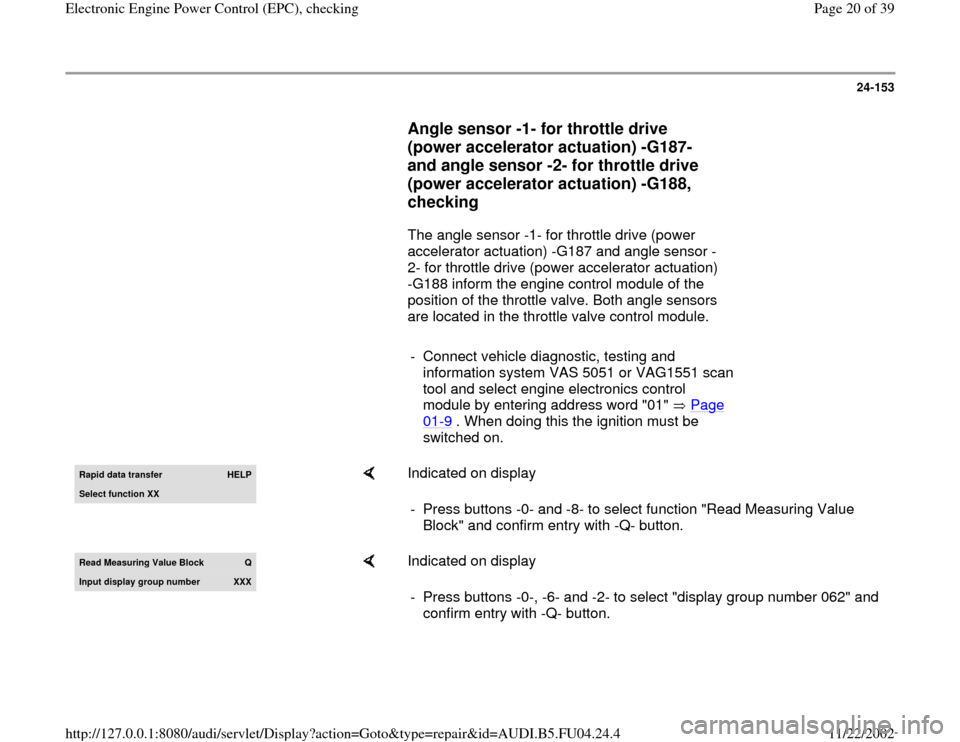
Rapid data transfer
HELP
Select function XX
Indicated on display
- Press buttons -0- and -8- to select function "Read Measuring Value
Block" and confirm entry with -Q- button.
Read Measurin
g Value Block
Q
Input displa
y group number
XXX
Indicated on display
- Press buttons -0-, -6- and -2- to select "display group number 062" and
confirm entry with -Q- button.
Pa
ge 20 of 39 Electronic En
gine Power Control
(EPC
), checkin
g
11/22/2002 htt
p://127.0.0.1:8080/audi/servlet/Dis
play?action=Goto&t
yp
e=re
pair&id=AUDI.B5.FU04.24.4