engine coolant AUDI A4 1995 B5 / 1.G APB Engine Ignition System Checking
[x] Cancel search | Manufacturer: AUDI, Model Year: 1995, Model line: A4, Model: AUDI A4 1995 B5 / 1.GPages: 64, PDF Size: 0.37 MB
Page 20 of 64
28-18
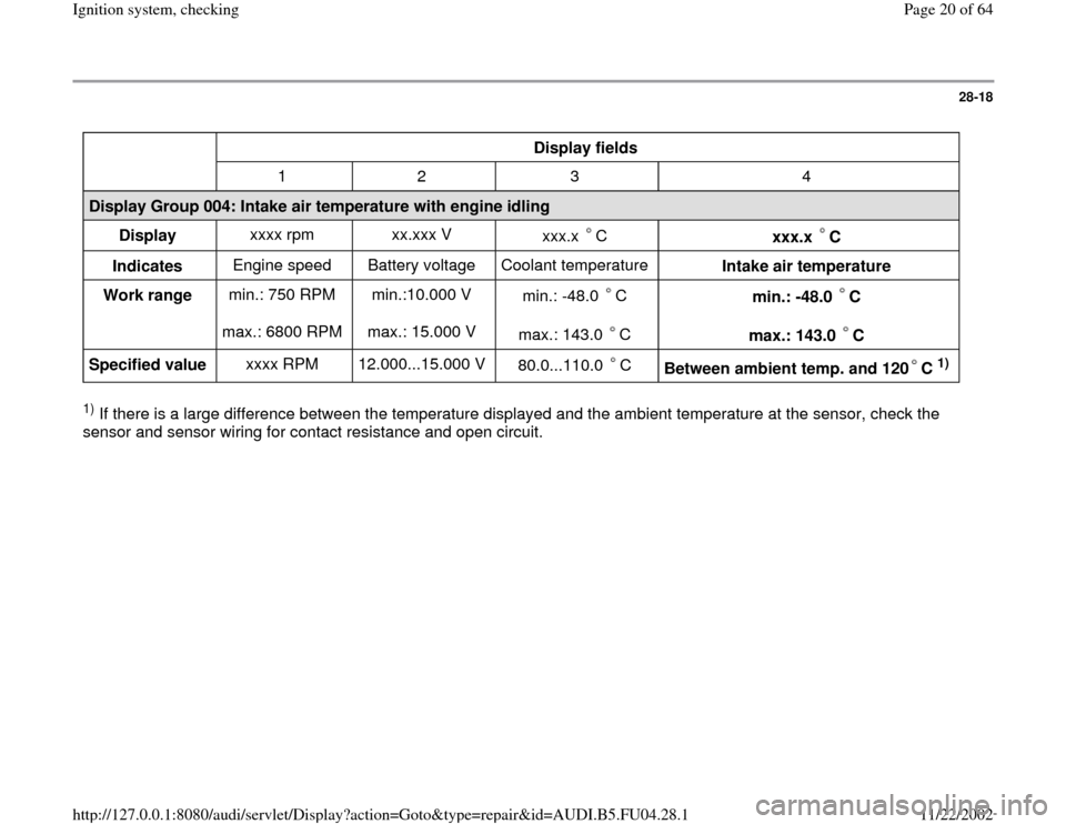
Display fields
1 2 3 4
Display Group 004: Intake air temperature with engine idling
Display xxxx rpm xx.xxx V
xxx.x C
xxx.x C
Indicates Engine speed Battery voltage Coolant temperature
Intake air temperature
Work range min.: 750 RPM
max.: 6800 RPM min.:10.000 V
max.: 15.000 V min.: -48.0 C
max.: 143.0 C
min.: -48.0 C
max.: 143.0 C
Specified value xxxx RPM 12.000...15.000 V
80.0...110.0 C
Between ambient temp. and 120 C
1)
1) If there is a large difference between the temperature displayed and the ambient temperature at the sensor, check the
sensor and sensor wiring for contact resistance and open circuit.
Pa
ge 20 of 64 I
gnition s
ystem, checkin
g
11/22/2002 htt
p://127.0.0.1:8080/audi/servlet/Dis
play?action=Goto&t
yp
e=re
pair&id=AUDI.B5.FU04.28.1
Page 28 of 64
28-25
Engine Coolant Temperature (ECT)
sensor -G62, checking
Note:
Component location of coolant temperature
sensor Page 24
-5 .
Test conditions
Engine cold
- Connect vehicle diagnostic, testing and
information system VAS 5051 or VAG1551 scan
tool to vehicle and select engine electronics
control module by entering address word "01"
Page 01
-9 .
When doing this the engine must be at idle.
Pa
ge 28 of 64 I
gnition s
ystem, checkin
g
11/22/2002 htt
p://127.0.0.1:8080/audi/servlet/Dis
play?action=Goto&t
yp
e=re
pair&id=AUDI.B5.FU04.28.1
Page 30 of 64
28-27
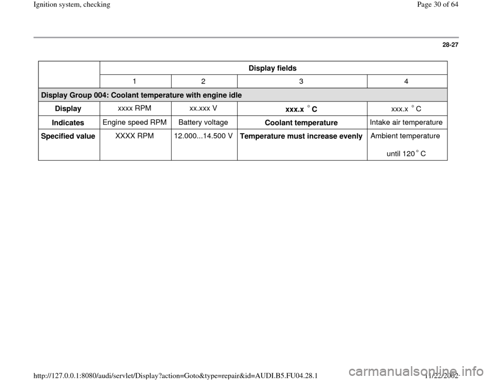
Display fields
1 2 3 4
Display Group 004: Coolant temperature with engine idle
Display xxxx RPM xx.xxx V
xxx.x C
xxx.x C
Indicates Engine speed RPM Battery voltage
Coolant temperature Intake air temperature
Specified value XXXX RPM 12.000...14.500 V
Temperature must increase evenly Ambient temperature
until 120 C
Pa
ge 30 of 64 I
gnition s
ystem, checkin
g
11/22/2002 htt
p://127.0.0.1:8080/audi/servlet/Dis
play?action=Goto&t
yp
e=re
pair&id=AUDI.B5.FU04.28.1
Page 33 of 64
28-30
If the value does match the specification:
- Connect test box VAG1598/31 to wiring harness
for engine control module. Do not connect to the
engine control module itself. Page 24
-20
.
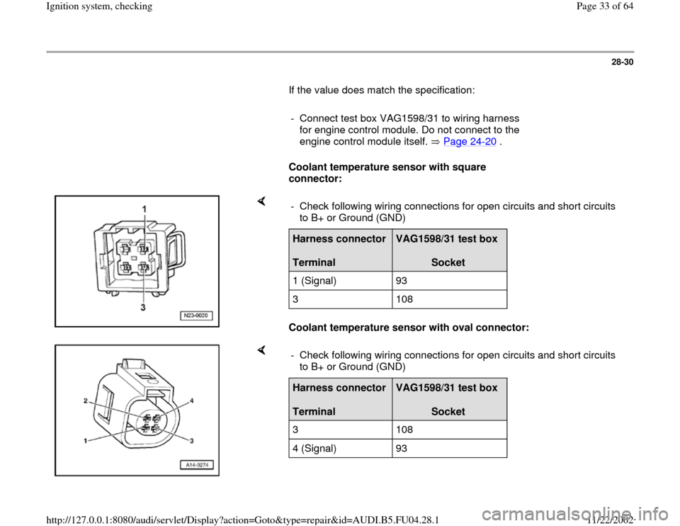
Coolant temperature sensor with square
connector:
Coolant temperature sensor with oval connector: - Check following wiring connections for open circuits and short circuits
to B+ or Ground (GND) Harness connector
Terminal
VAG1598/31 test box
Socket
1 (Signal) 93
3 108
- Check following wiring connections for open circuits and short circuits
to B+ or Ground (GND) Harness connector
Terminal
VAG1598/31 test box
Socket
3 108
4 (Signal) 93
Pa
ge 33 of 64 I
gnition s
ystem, checkin
g
11/22/2002 htt
p://127.0.0.1:8080/audi/servlet/Dis
play?action=Goto&t
yp
e=re
pair&id=AUDI.B5.FU04.28.1
Page 46 of 64
28-41
Knock Sensor (KS) 1 -G61 and Knock
Sensor (KS) 2 -G66, checking
Notes:
It is not possible to carry out an electrical test of
the knock sensors themselves.
To ensure that the knock sensors function
properly it is important to keep exactly to the
specified tightening torque of 20 Nm (15 ft lb)
Use only gold-plated terminals when repairing
the terminals in the plug connectors for the
knock sensors.
Check for corrosion in connection between
knock sensor and wiring harness.
Checking knock sensors
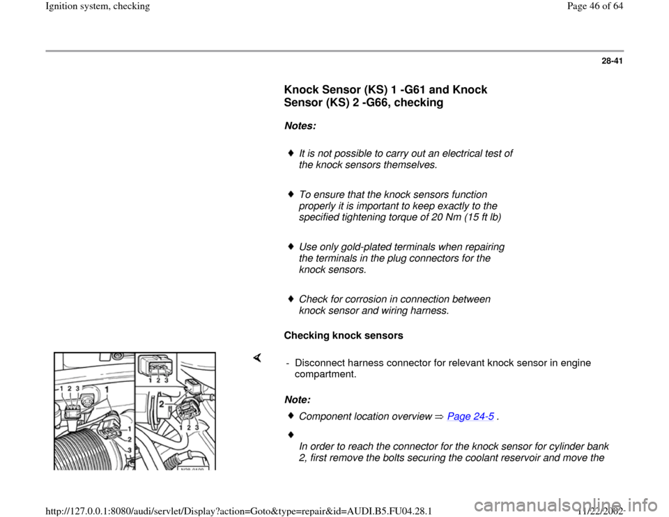
Note: - Disconnect harness connector for relevant knock sensor in engine
compartment.
Component location overview Page 24
-5 .
In order to reach the connector for the knock sensor for cylinder bank
2, first remove the bolts securing the coolant reservoir and move the
Pa
ge 46 of 64 I
gnition s
ystem, checkin
g
11/22/2002 htt
p://127.0.0.1:8080/audi/servlet/Dis
play?action=Goto&t
yp
e=re
pair&id=AUDI.B5.FU04.28.1