AUDI A4 1995 B5 / 1.G AWM Engine Exhaust System Components Workshop Manual
Manufacturer: AUDI, Model Year: 1995,
Model line: A4,
Model: AUDI A4 1995 B5 / 1.G
Pages: 41, PDF Size: 0.7 MB
AUDI A4 1995 B5 / 1.G AWM Engine Exhaust System Components Workshop Manual
A4 1995 B5 / 1.G
AUDI
AUDI
https://www.carmanualsonline.info/img/6/935/w960_935-0.png
AUDI A4 1995 B5 / 1.G AWM Engine Exhaust System Components Workshop Manual
Trending: ignition, check engine, oil temperature, air filter, sensor, tow, coolant
Page 1 of 41
26-1
Exhaust system components,
removing and installing
Note:
Always replace seals, gaskets and self-locking
nuts.
After working on the exhaust system ensure
that the system is not under stress, and that it
has sufficient clearance from the bodywork. If
necessary, loosen clamps and align mufflers
and exhaust pipes so that sufficient clearance is
maintained to the bodywork at all points and the
mountings are evenly loaded.
The flexible connection in the front exhaust pipe
must not be deflected more than 10 or it may
be damaged..
Pa
ge 1 of 41 Exhaust s
ystem com
ponents, removin
g and installin
g
11/21/2002 htt
p://127.0.0.1:8080/audi/servlet/Dis
play?action=Goto&t
yp
e=re
pair&id=AUDI.B5.GE06.26.1
Page 2 of 41
26-2
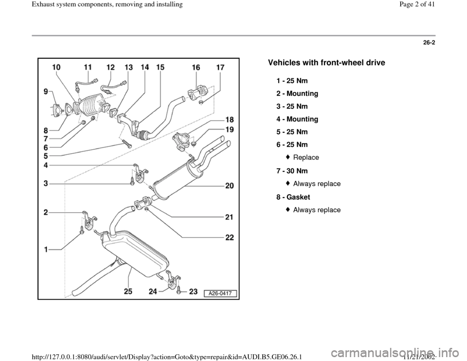
Vehicles with front-wheel drive
1 -
25 Nm
2 -
Mounting
3 -
25 Nm
4 -
Mounting
5 -
25 Nm
6 -
25 Nm
Replace
7 -
30 Nm Always replace
8 -
Gasket Always replace
Pa
ge 2 of 41 Exhaust s
ystem com
ponents, removin
g and installin
g
11/21/2002 htt
p://127.0.0.1:8080/audi/servlet/Dis
play?action=Goto&t
yp
e=re
pair&id=AUDI.B5.GE06.26.1
Page 3 of 41
26-3
Repair Manual, 1.8 Liter 4
-Cyl. 5V Turbo Fuel
Injection & Ignition, Engine Code(s): AWM, Repair Group 24
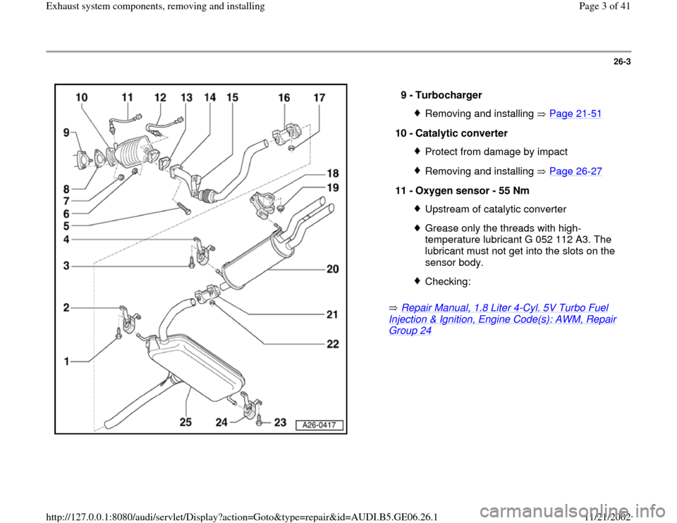
9 -
Turbocharger Removing and installing Page 21
-51
10 -
Catalytic converter
Protect from damage by impactRemoving and installing Page 26
-27
11 -
Oxygen sensor - 55 Nm
Upstream of catalytic converterGrease only the threads with high-
temperature lubricant G 052 112 A3. The
lubricant must not get into the slots on the
sensor body. Checking:
Pa
ge 3 of 41 Exhaust s
ystem com
ponents, removin
g and installin
g
11/21/2002 htt
p://127.0.0.1:8080/audi/servlet/Dis
play?action=Goto&t
yp
e=re
pair&id=AUDI.B5.GE06.26.1
Page 4 of 41
26-4
Repair Manual, 1.8 Liter 4
-Cyl. 5V Turbo Fuel
Injection & Ignition, Engine Code(s): AWM, Repair Group 24
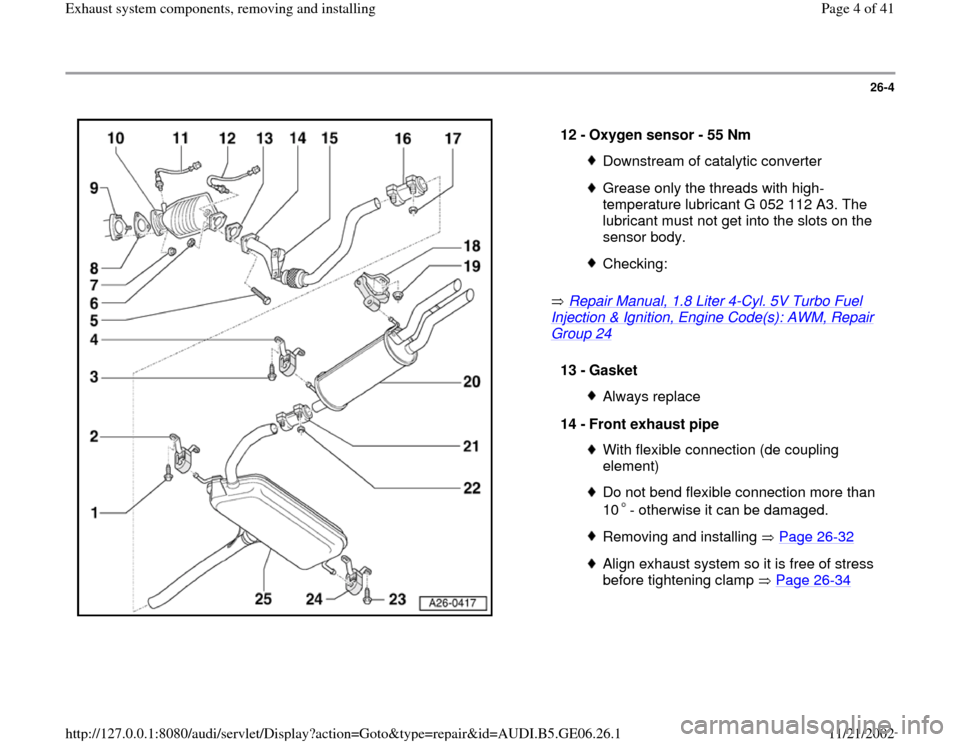
12 -
Oxygen sensor - 55 Nm Downstream of catalytic converterGrease only the threads with high-
temperature lubricant G 052 112 A3. The
lubricant must not get into the slots on the
sensor body. Checking:
13 -
Gasket
Always replace
14 -
Front exhaust pipe With flexible connection (de coupling
element) Do not bend flexible connection more than
10 - otherwise it can be damaged. Removing and installing Page 26
-32
Align exhaust system so it is free of stress
before tightening clamp Page 26
-34
Pa
ge 4 of 41 Exhaust s
ystem com
ponents, removin
g and installin
g
11/21/2002 htt
p://127.0.0.1:8080/audi/servlet/Dis
play?action=Goto&t
yp
e=re
pair&id=AUDI.B5.GE06.26.1
Page 5 of 41
26-5
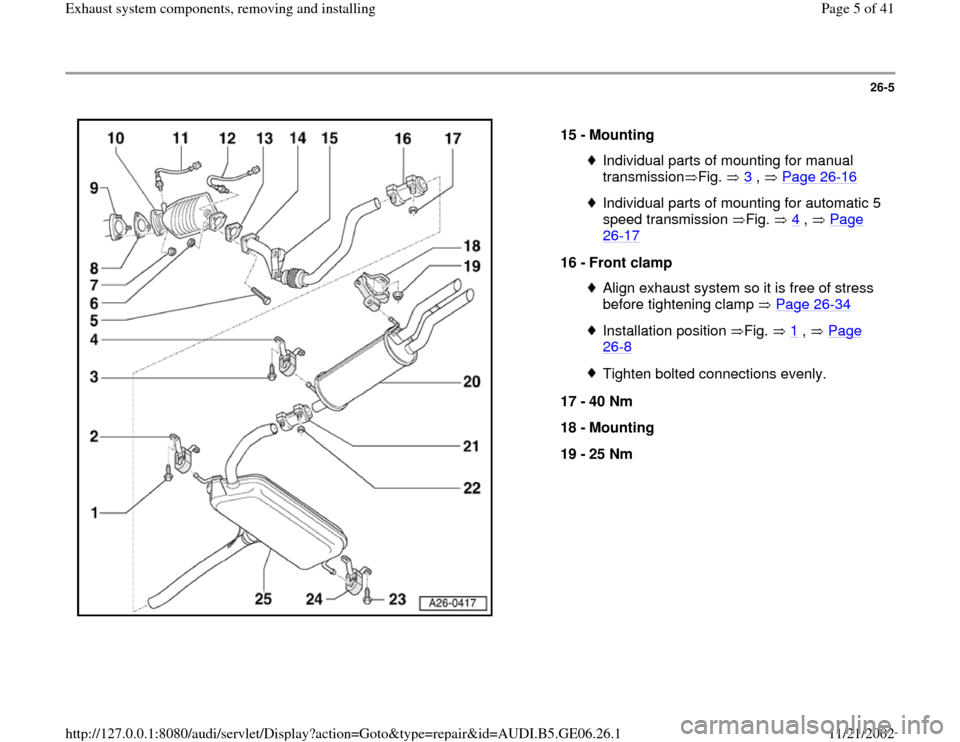
15 -
Mounting
Individual parts of mounting for manual
transmission Fig. 3
, Page 26
-16
Individual parts of mounting for automatic 5
speed transmission Fig. 4
, Page
26
-17
16 -
Front clamp
Align exhaust system so it is free of stress
before tightening clamp Page 26
-34
Installation position Fig. 1
, Page
26
-8
Tighten bolted connections evenly.
17 -
40 Nm
18 -
Mounting
19 -
25 Nm
Pa
ge 5 of 41 Exhaust s
ystem com
ponents, removin
g and installin
g
11/21/2002 htt
p://127.0.0.1:8080/audi/servlet/Dis
play?action=Goto&t
yp
e=re
pair&id=AUDI.B5.GE06.26.1
Page 6 of 41
26-6
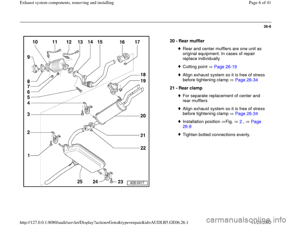
20 -
Rear muffler
Rear and center mufflers are one unit as
original equipment. In cases of repair
replace individually Cutting point Page 26
-19
Align exhaust system so it is free of stress
before tightening clamp Page 26
-34
21 -
Rear clamp
For separate replacement of center and
rear mufflers Align exhaust system so it is free of stress
before tightening clamp Page 26
-34
Installation position Fig. 2
, Page
26
-8
Tighten bolted connections evenly.
Pa
ge 6 of 41 Exhaust s
ystem com
ponents, removin
g and installin
g
11/21/2002 htt
p://127.0.0.1:8080/audi/servlet/Dis
play?action=Goto&t
yp
e=re
pair&id=AUDI.B5.GE06.26.1
Page 7 of 41
26-7
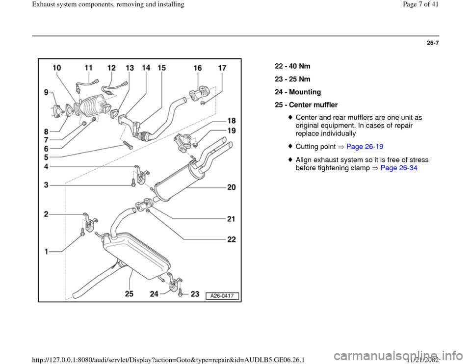
22 -
40 Nm
23 -
25 Nm
24 -
Mounting
25 -
Center muffler
Center and rear mufflers are one unit as
original equipment. In cases of repair
replace individually Cutting point Page 26
-19
Align exhaust system so it is free of stress
before tightening clamp Page 26
-34
Pa
ge 7 of 41 Exhaust s
ystem com
ponents, removin
g and installin
g
11/21/2002 htt
p://127.0.0.1:8080/audi/servlet/Dis
play?action=Goto&t
yp
e=re
pair&id=AUDI.B5.GE06.26.1
Page 8 of 41
26-8
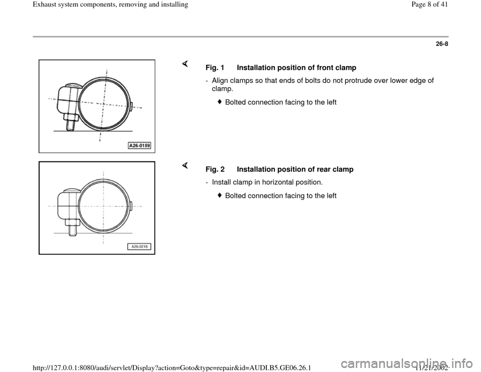
Fig. 1 Installation position of front clamp
- Align clamps so that ends of bolts do not protrude over lower edge of
clamp.
Bolted connection facing to the left
Fig. 2 Installation position of rear clamp
- Install clamp in horizontal position.
Bolted connection facing to the left
Pa
ge 8 of 41 Exhaust s
ystem com
ponents, removin
g and installin
g
11/21/2002 htt
p://127.0.0.1:8080/audi/servlet/Dis
play?action=Goto&t
yp
e=re
pair&id=AUDI.B5.GE06.26.1
Page 9 of 41
26-9
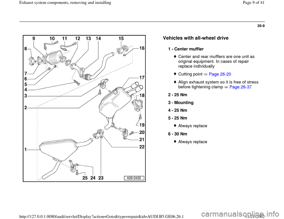
Vehicles with all-wheel drive
1 -
Center muffler
Center and rear mufflers are one unit as
original equipment. In cases of repair
replace individually Cutting point Page 26
-20
Align exhaust system so it is free of stress
before tightening clamp Page 26
-37
2 -
25 Nm
3 -
Mounting
4 -
25 Nm
5 -
25 Nm
Always replace
6 -
30 Nm Always replace
Pa
ge 9 of 41 Exhaust s
ystem com
ponents, removin
g and installin
g
11/21/2002 htt
p://127.0.0.1:8080/audi/servlet/Dis
play?action=Goto&t
yp
e=re
pair&id=AUDI.B5.GE06.26.1
Page 10 of 41
26-10
Repair Manual, 1.8 Liter 4
-Cyl. 5V Turbo Fuel
Injection & Ignition, Engine Code(s): AWM, Repair Group 24
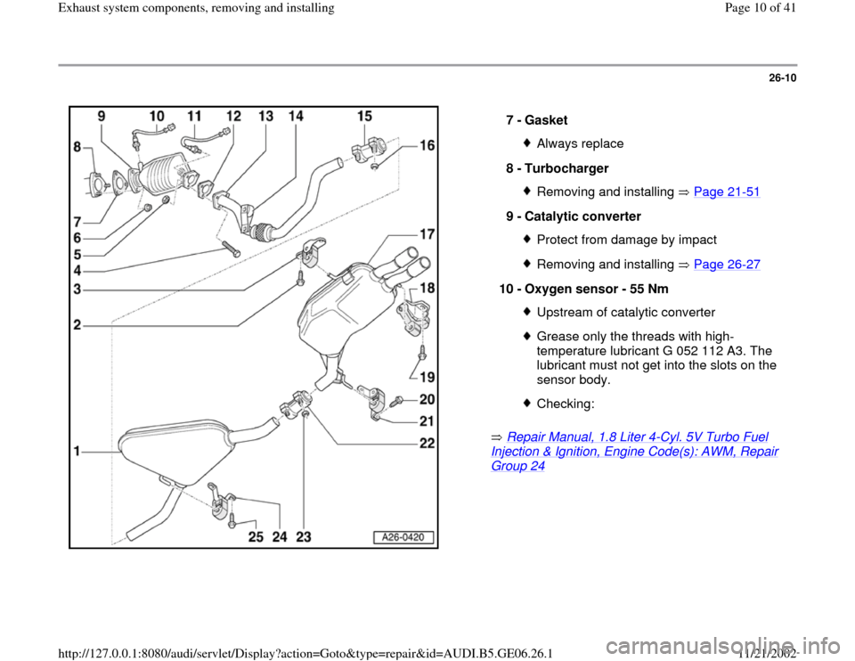
7 -
Gasket Always replace
8 -
Turbocharger Removing and installing Page 21
-51
9 -
Catalytic converter
Protect from damage by impactRemoving and installing Page 26
-27
10 -
Oxygen sensor - 55 Nm
Upstream of catalytic converterGrease only the threads with high-
temperature lubricant G 052 112 A3. The
lubricant must not get into the slots on the
sensor body. Checking:
Pa
ge 10 of 41 Exhaust s
ystem com
ponents, removin
g and installin
g
11/21/2002 htt
p://127.0.0.1:8080/audi/servlet/Dis
play?action=Goto&t
yp
e=re
pair&id=AUDI.B5.GE06.26.1
Trending: coolant, fuel, lock, engine coolant, stop start, wheel, ignition
