wiring AUDI A4 1995 B5 / 1.G APB Engine Oxygen Sensor Control Checking User Guide
[x] Cancel search | Manufacturer: AUDI, Model Year: 1995, Model line: A4, Model: AUDI A4 1995 B5 / 1.GPages: 61, PDF Size: 0.27 MB
Page 52 of 61
24-124
Electrical Wiring Diagrams, Troubleshooting & Component Locations
Electrical Wiring Diagrams, Troubleshooting & Component Locations
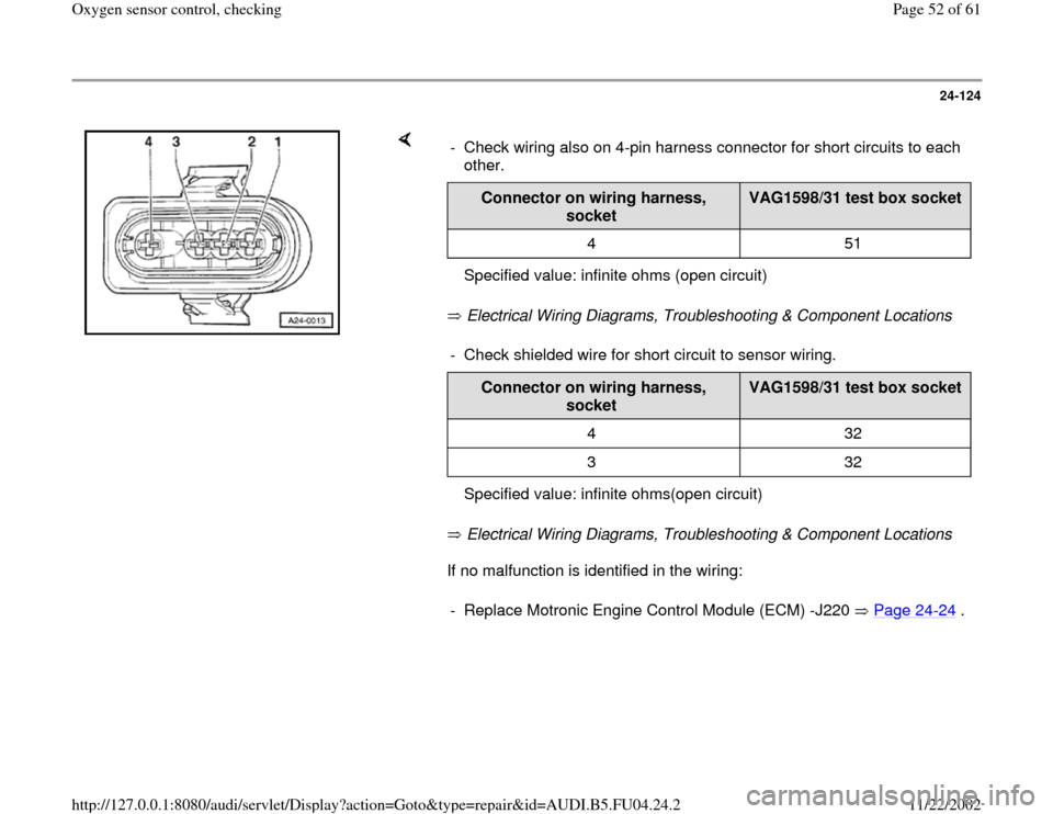
If no malfunction is identified in the wiring: - Check wiring also on 4-pin harness connector for short circuits to each
other.
Connector on wiring harness,
socket
VAG1598/31 test box socket
4 51
Specified value: infinite ohms (open circuit)- Check shielded wire for short circuit to sensor wiring.
Connector on wiring harness,
socket
VAG1598/31 test box socket
4 32
3 32
Specified value: infinite ohms(open circuit)- Replace Motronic Engine Control Module (ECM) -J220 Page 24
-24
.
Pa
ge 52 of 61 Ox
yg
en sensor control, checkin
g
11/22/2002 htt
p://127.0.0.1:8080/audi/servlet/Dis
play?action=Goto&t
yp
e=re
pair&id=AUDI.B5.FU04.24.2
Page 53 of 61
24-125
Checking wiring for Oxygen Sensor (O2S)
Behind Three Way Catalytic Converter (TWC)
-G130
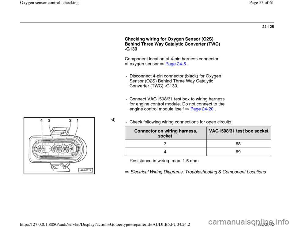
Component location of 4-pin harness connector
of oxygen sensor Page 24
-5 .
- Disconnect 4-pin connector (black) for Oxygen
Sensor (O2S) Behind Three Way Catalytic
Converter (TWC) -G130.
- Connect VAG1598/31 test box to wiring harness
for engine control module. Do not connect to the
engine control module itself Page 24
-20
.
Electrical Wiring Diagrams, Troubleshooting & Component Locations - Check following wiring connections for open circuits:
Connector on wiring harness,
socket
VAG1598/31 test box socket
3 68
4 69
Resistance in wiring: max. 1.5 ohm
Pa
ge 53 of 61 Ox
yg
en sensor control, checkin
g
11/22/2002 htt
p://127.0.0.1:8080/audi/servlet/Dis
play?action=Goto&t
yp
e=re
pair&id=AUDI.B5.FU04.24.2
Page 54 of 61
24-126
Electrical Wiring Diagrams, Troubleshooting & Component Locations
Electrical Wiring Diagrams, Troubleshooting & Component Locations
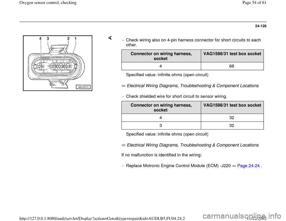
If no malfunction is identified in the wiring: - Check wiring also on 4-pin harness connector for short circuits to each
other.
Connector on wiring harness,
socket
VAG1598/31 test box socket
4 68
Specified value: infinite ohms (open circuit)- Check shielded wire for short circuit to sensor wiring.
Connector on wiring harness,
socket
VAG1598/31 test box socket
4 32
3 32
Specified value: infinite ohms (open circuit)- Replace Motronic Engine Control Module (ECM) -J220 Page 24
-24
.
Pa
ge 54 of 61 Ox
yg
en sensor control, checkin
g
11/22/2002 htt
p://127.0.0.1:8080/audi/servlet/Dis
play?action=Goto&t
yp
e=re
pair&id=AUDI.B5.FU04.24.2
Page 55 of 61
24-127
Checking wiring for Heated Oxygen Sensor
(HO2S) 2 -G108
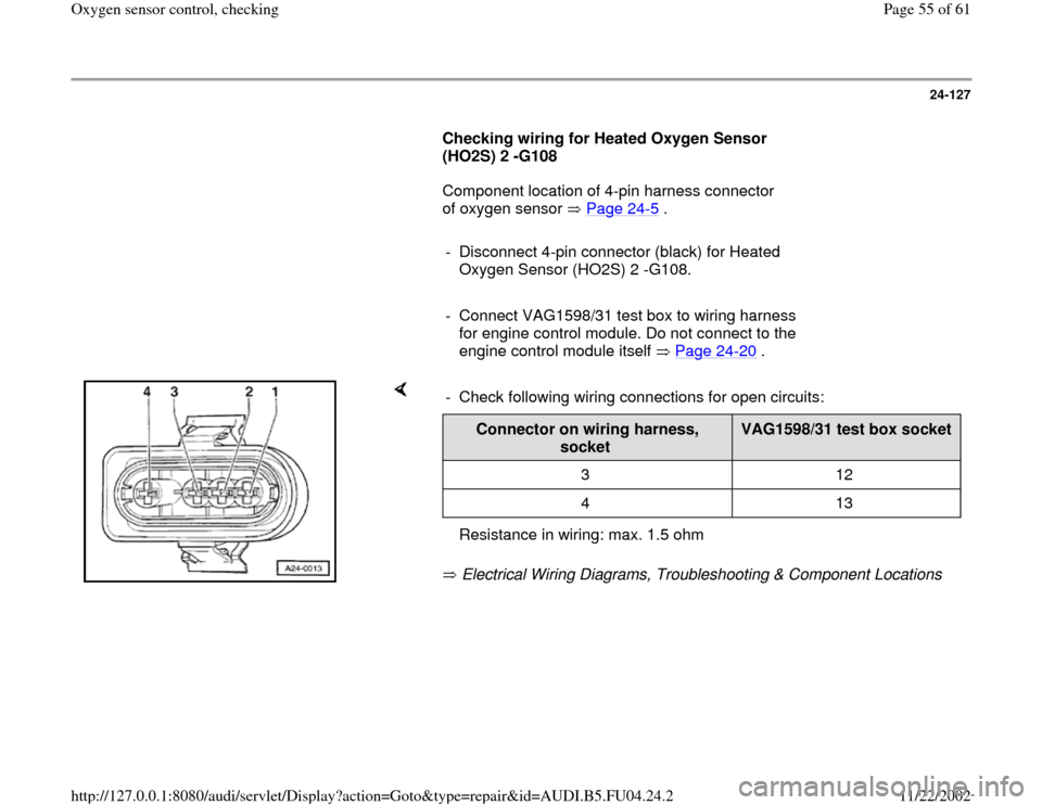
Component location of 4-pin harness connector
of oxygen sensor Page 24
-5 .
- Disconnect 4-pin connector (black) for Heated
Oxygen Sensor (HO2S) 2 -G108.
- Connect VAG1598/31 test box to wiring harness
for engine control module. Do not connect to the
engine control module itself Page 24
-20
.
Electrical Wiring Diagrams, Troubleshooting & Component Locations - Check following wiring connections for open circuits:
Connector on wiring harness,
socket
VAG1598/31 test box socket
3 12
4 13
Resistance in wiring: max. 1.5 ohm
Pa
ge 55 of 61 Ox
yg
en sensor control, checkin
g
11/22/2002 htt
p://127.0.0.1:8080/audi/servlet/Dis
play?action=Goto&t
yp
e=re
pair&id=AUDI.B5.FU04.24.2
Page 56 of 61
24-128
Electrical Wiring Diagrams, Troubleshooting & Component Locations
Electrical Wiring Diagrams, Troubleshooting & Component Locations
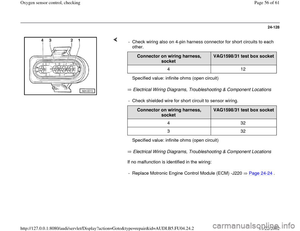
If no malfunction is identified in the wiring: - Check wiring also on 4-pin harness connector for short circuits to each
other.
Connector on wiring harness,
socket
VAG1598/31 test box socket
4 12
Specified value: infinite ohms (open circuit)- Check shielded wire for short circuit to sensor wiring.
Connector on wiring harness,
socket
VAG1598/31 test box socket
4 32
3 32
Specified value: infinite ohms (open circuit)- Replace Motronic Engine Control Module (ECM) -J220 Page 24
-24
.
Pa
ge 56 of 61 Ox
yg
en sensor control, checkin
g
11/22/2002 htt
p://127.0.0.1:8080/audi/servlet/Dis
play?action=Goto&t
yp
e=re
pair&id=AUDI.B5.FU04.24.2
Page 57 of 61
24-129
Checking wiring for Oxygen Sensor (O2S) 2
Behind Three Way Catalytic Converter (TWC)
-G131
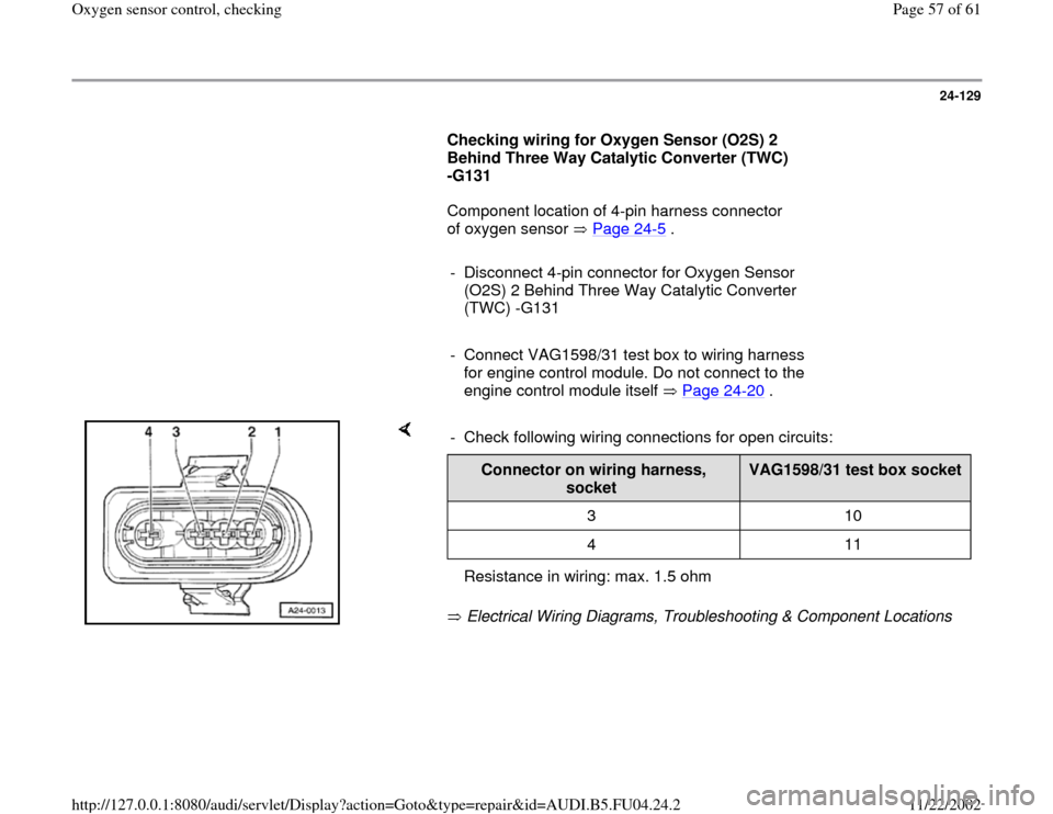
Component location of 4-pin harness connector
of oxygen sensor Page 24
-5 .
- Disconnect 4-pin connector for Oxygen Sensor
(O2S) 2 Behind Three Way Catalytic Converter
(TWC) -G131
- Connect VAG1598/31 test box to wiring harness
for engine control module. Do not connect to the
engine control module itself Page 24
-20
.
Electrical Wiring Diagrams, Troubleshooting & Component Locations - Check following wiring connections for open circuits:
Connector on wiring harness,
socket
VAG1598/31 test box socket
3 10
4 11
Resistance in wiring: max. 1.5 ohm
Pa
ge 57 of 61 Ox
yg
en sensor control, checkin
g
11/22/2002 htt
p://127.0.0.1:8080/audi/servlet/Dis
play?action=Goto&t
yp
e=re
pair&id=AUDI.B5.FU04.24.2
Page 58 of 61
24-130
Electrical Wiring Diagrams, Troubleshooting & Component Locations
Electrical Wiring Diagrams, Troubleshooting & Component Locations
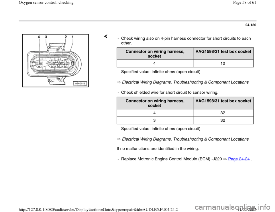
If no malfunctions are identified in the wiring: - Check wiring also on 4-pin harness connector for short circuits to each
other.
Connector on wiring harness,
socket
VAG1598/31 test box socket
4 10
Specified value: infinite ohms (open circuit)- Check shielded wire for short circuit to sensor wiring.
Connector on wiring harness,
socket
VAG1598/31 test box socket
4 32
3 32
Specified value: infinite ohms (open circuit)- Replace Motronic Engine Control Module (ECM) -J220 Page 24
-24
.
Pa
ge 58 of 61 Ox
yg
en sensor control, checkin
g
11/22/2002 htt
p://127.0.0.1:8080/audi/servlet/Dis
play?action=Goto&t
yp
e=re
pair&id=AUDI.B5.FU04.24.2
Page 59 of 61
24-131
If no malfunction can be identified in the wiring:
- Replace Motronic Engine Control Module (ECM)
-J220 Page 24
-24
.
- Display readiness code Page 01
-101
. The
readiness code must be generated if the DTC
memory was erased Page 01
-105
.
Pa
ge 59 of 61 Ox
yg
en sensor control, checkin
g
11/22/2002 htt
p://127.0.0.1:8080/audi/servlet/Dis
play?action=Goto&t
yp
e=re
pair&id=AUDI.B5.FU04.24.2
Page 61 of 61
24-133
When installing observe the following:
Note:
The wiring from the oxygen sensor must be
fastened at the exact location as previously
installed, to avoid contact with exhaust pipe.
The oxygen sensor threads are coated with a
tread sealing compound that must not come in
contact with the slits in the sensor tip.
Tightening torque: 55 Nm (41 ft lb)
Pa
ge 61 of 61 Ox
yg
en sensor control, checkin
g
11/22/2002 htt
p://127.0.0.1:8080/audi/servlet/Dis
play?action=Goto&t
yp
e=re
pair&id=AUDI.B5.FU04.24.2