sensor AUDI A4 1995 B5 / 1.G ATQ Engine Motronic Injection System Servicing Workshop Manual
[x] Cancel search | Manufacturer: AUDI, Model Year: 1995, Model line: A4, Model: AUDI A4 1995 B5 / 1.GPages: 78, PDF Size: 1 MB
Page 7 of 78
24-5
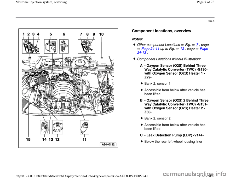
Component locations, overview
Notes:
Other component Locations Fig. 7
, page
Page 24
-11
up to Fig. 12
, page Page
24
-13
.
Component Locations without illustration:
A - Oxygen Sensor (O2S) Behind Three
Way Catalytic Converter (TWC) -G130-
with Oxygen Sensor (O2S) Heater 1 -
Z29-
Bank 2, sensor 1Accessible from below after vehicle has
been lifted
B - Oxygen Sensor (O2S) 2 Behind Three
Way Catalytic Converter (TWC) -G131-
with Oxygen Sensor (O2S) Heater 2 -
Z30- Bank 2, sensor 2Accessible from below after vehicle has
been lifted
C - Leak Detection Pump (LDP) -V144-Below the rear left wheelhousing liner
Pa
ge 7 of 78 Motronic in
jection s
ystem, servicin
g
11/23/2002 htt
p://127.0.0.1:8080/audi/servlet/Dis
play?action=Goto&t
yp
e=re
pair&id=AUDI.B5.FU05.24.1
Page 8 of 78
24-6
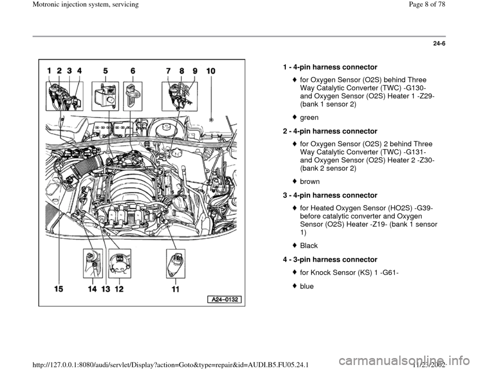
1 -
4-pin harness connector
for Oxygen Sensor (O2S) behind Three
Way Catalytic Converter (TWC) -G130-
and Oxygen Sensor (O2S) Heater 1 -Z29-
(bank 1 sensor 2) green
2 -
4-pin harness connector for Oxygen Sensor (O2S) 2 behind Three
Way Catalytic Converter (TWC) -G131-
and Oxygen Sensor (O2S) Heater 2 -Z30-
(bank 2 sensor 2) brown
3 -
4-pin harness connector for Heated Oxygen Sensor (HO2S) -G39-
before catalytic converter and Oxygen
Sensor (O2S) Heater -Z19- (bank 1 sensor
1) Black
4 -
3-pin harness connector for Knock Sensor (KS) 1 -G61-blue
Pa
ge 8 of 78 Motronic in
jection s
ystem, servicin
g
11/23/2002 htt
p://127.0.0.1:8080/audi/servlet/Dis
play?action=Goto&t
yp
e=re
pair&id=AUDI.B5.FU05.24.1
Page 9 of 78
24-7
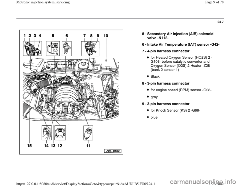
5 -
Secondary Air Injection (AIR) solenoid
valve -N112-
6 -
Intake Air Temperature (IAT) sensor -G42-
7 -
4-pin harness connector
for Heated Oxygen Sensor (HO2S) 2 -
G108- before catalytic converter and
Oxygen Sensor (O2S) 2 Heater -Z28-
(bank 2 sensor 1) Black
8 -
3-pin harness connector for engine speed (RPM) sensor -G28-gray
9 -
3-pin harness connector for Knock Sensor (KS) 2 -G66-blue
Pa
ge 9 of 78 Motronic in
jection s
ystem, servicin
g
11/23/2002 htt
p://127.0.0.1:8080/audi/servlet/Dis
play?action=Goto&t
yp
e=re
pair&id=AUDI.B5.FU05.24.1
Page 10 of 78
24-8
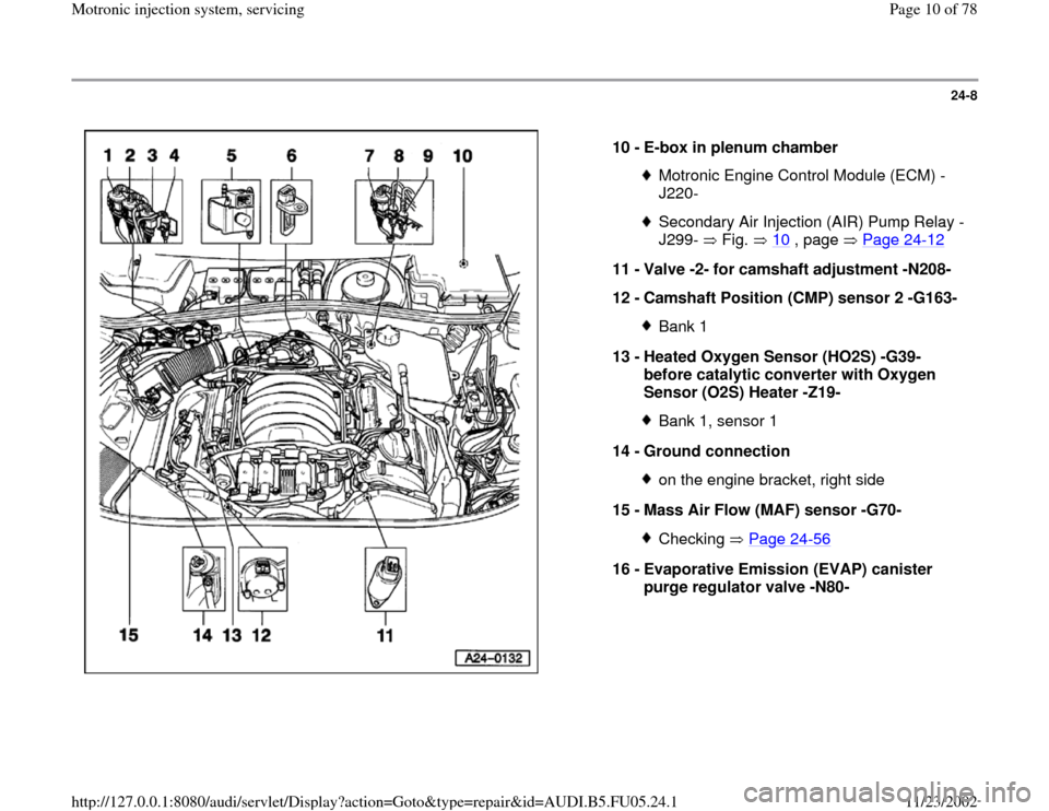
10 -
E-box in plenum chamber
Motronic Engine Control Module (ECM) -
J220- Secondary Air Injection (AIR) Pump Relay -
J299- Fig. 10
, page Page 24
-12
11 -
Valve -2- for camshaft adjustment -N208-
12 -
Camshaft Position (CMP) sensor 2 -G163-
Bank 1
13 -
Heated Oxygen Sensor (HO2S) -G39-
before catalytic converter with Oxygen
Sensor (O2S) Heater -Z19- Bank 1, sensor 1
14 -
Ground connection on the engine bracket, right side
15 -
Mass Air Flow (MAF) sensor -G70- Checking Page 24
-56
16 -
Evaporative Emission (EVAP) canister
purge regulator valve -N80-
Pa
ge 10 of 78 Motronic in
jection s
ystem, servicin
g
11/23/2002 htt
p://127.0.0.1:8080/audi/servlet/Dis
play?action=Goto&t
yp
e=re
pair&id=AUDI.B5.FU05.24.1
Page 11 of 78
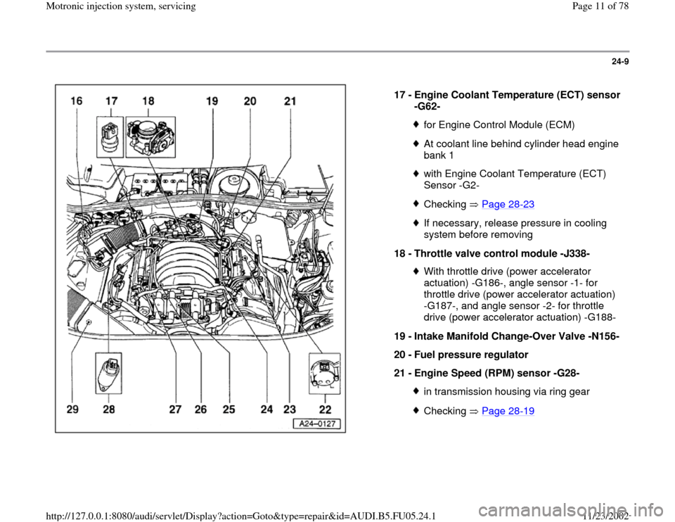
24-9
17 -
Engine Coolant Temperature (ECT) sensor
-G62-
for Engine Control Module (ECM)At coolant line behind cylinder head engine
bank 1 with Engine Coolant Temperature (ECT)
Sensor -G2- Checking Page 28
-23
If necessary, release pressure in cooling
system before removing
18 -
Throttle valve control module -J338- With throttle drive (power accelerator
actuation) -G186-, angle sensor -1- for
throttle drive (power accelerator actuation)
-G187-, and angle sensor -2- for throttle
drive (power accelerator actuation) -G188-
19 -
Intake Manifold Change-Over Valve -N156-
20 -
Fuel pressure regulator
21 -
Engine Speed (RPM) sensor -G28- in transmission housing via ring gearChecking Page 28
-19
Pa
ge 11 of 78 Motronic in
jection s
ystem, servicin
g
11/23/2002 htt
p://127.0.0.1:8080/audi/servlet/Dis
play?action=Goto&t
yp
e=re
pair&id=AUDI.B5.FU05.24.1
Page 12 of 78
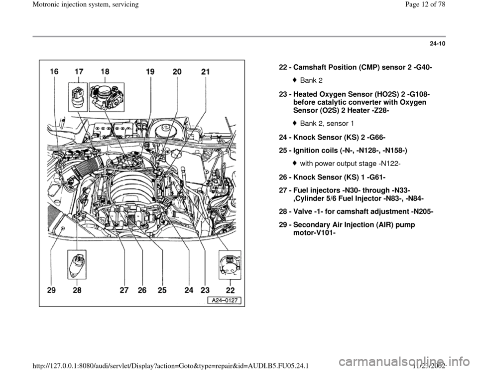
24-10
22 -
Camshaft Position (CMP) sensor 2 -G40-
Bank 2
23 -
Heated Oxygen Sensor (HO2S) 2 -G108-
before catalytic converter with Oxygen
Sensor (O2S) 2 Heater -Z28- Bank 2, sensor 1
24 -
Knock Sensor (KS) 2 -G66-
25 -
Ignition coils (-N-, -N128-, -N158-) with power output stage -N122-
26 -
Knock Sensor (KS) 1 -G61-
27 -
Fuel injectors -N30- through -N33-
,Cylinder 5/6 Fuel Injector -N83-, -N84-
28 -
Valve -1- for camshaft adjustment -N205-
29 -
Secondary Air Injection (AIR) pump
motor-V101-
Pa
ge 12 of 78 Motronic in
jection s
ystem, servicin
g
11/23/2002 htt
p://127.0.0.1:8080/audi/servlet/Dis
play?action=Goto&t
yp
e=re
pair&id=AUDI.B5.FU05.24.1
Page 13 of 78
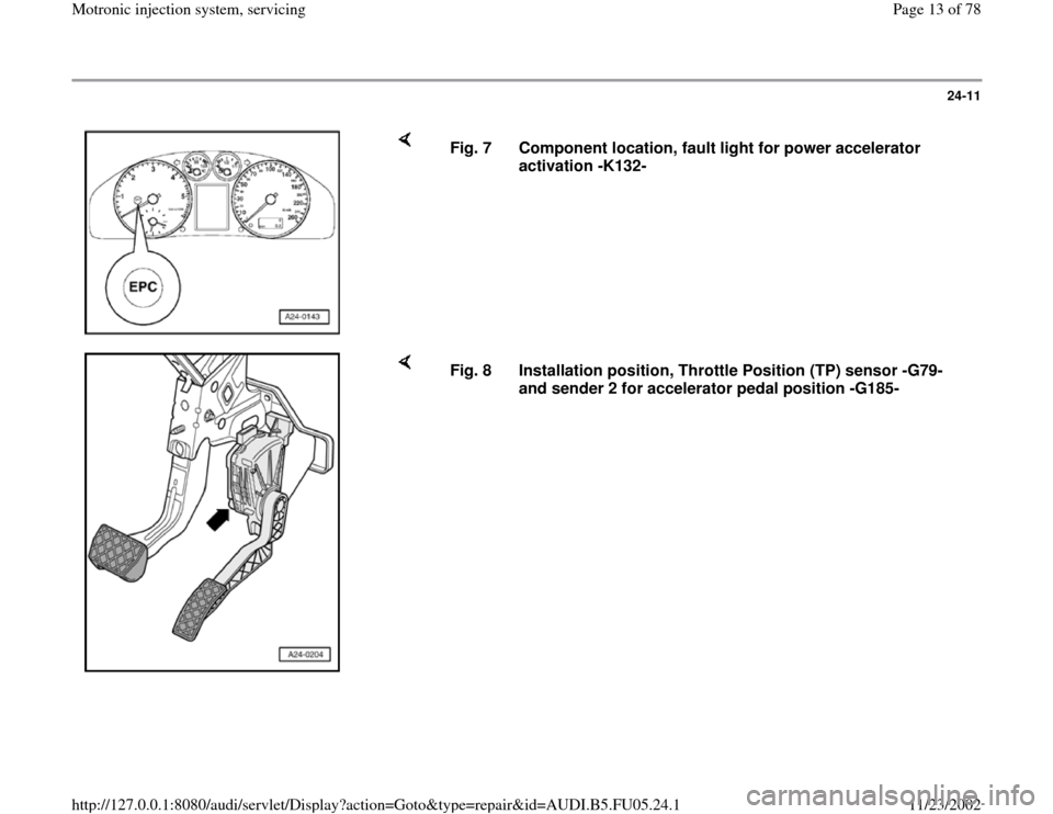
24-11
Fig. 7 Component location, fault light for power accelerator
activation -K132-
Fig. 8 Installation position, Throttle Position (TP) sensor -G79-
and sender 2 for accelerator pedal position -G185-
Pa
ge 13 of 78 Motronic in
jection s
ystem, servicin
g
11/23/2002 htt
p://127.0.0.1:8080/audi/servlet/Dis
play?action=Goto&t
yp
e=re
pair&id=AUDI.B5.FU05.24.1
Page 16 of 78
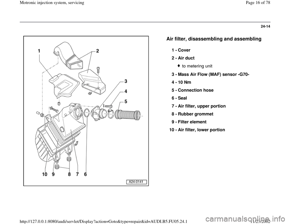
24-14
Air filter, disassembling and assembling
1 -
Cover
2 -
Air duct
to metering unit
3 -
Mass Air Flow (MAF) sensor -G70-
4 -
10 Nm
5 -
Connection hose
6 -
Seal
7 -
Air filter, upper portion
8 -
Rubber grommet
9 -
Filter element
10 -
Air filter, lower portion
Pa
ge 16 of 78 Motronic in
jection s
ystem, servicin
g
11/23/2002 htt
p://127.0.0.1:8080/audi/servlet/Dis
play?action=Goto&t
yp
e=re
pair&id=AUDI.B5.FU05.24.1
Page 37 of 78
24-32
- Measure fuel pressure.
Specification: 3.8 to 4.2 bar
- If the specified value is not reached, replace
pressure regulator on a trial basis and repeat
pressure test.
- If the specified value is not reached again, check
Fuel Pump (FP) or supply line for damage (e.g.
pinched areas) and replace if necessary.
- If the specified value is exceeded, check return
line for damage (e.g. pinched areas) and replace
if necessary.
Note:
During the following test, the engine must not run
for an unnecessarily long period of time with the
vacuum hose removed. Otherwise, the higher
fuel pressure can cause enrichment of the fuel to
air ratio, which under some circumstances can
cause the oxygen sensor control limits to be
exceeded, causing a DTC to be stored.
- Start engine and let run at idle.
-
Switch of electrical consumers (A/C system
Pa
ge 37 of 78 Motronic in
jection s
ystem, servicin
g
11/23/2002 htt
p://127.0.0.1:8080/audi/servlet/Dis
play?action=Goto&t
yp
e=re
pair&id=AUDI.B5.FU05.24.1
Page 51 of 78
24-43
Fuel injectors, removing and installing
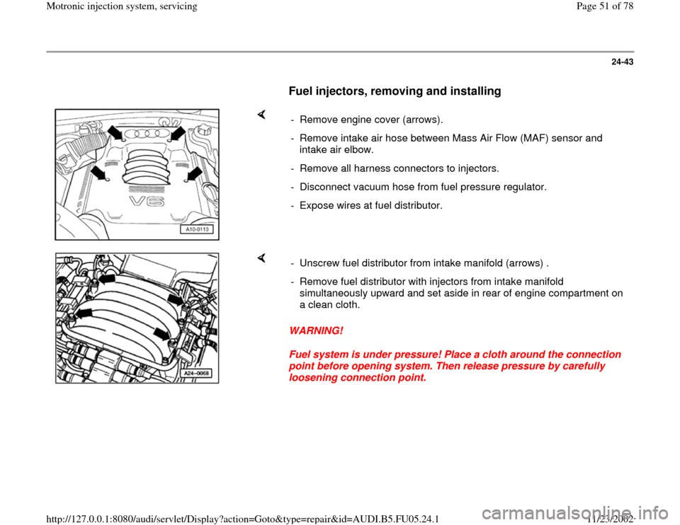
- Remove engine cover (arrows).
- Remove intake air hose between Mass Air Flow (MAF) sensor and
intake air elbow.
- Remove all harness connectors to injectors.
- Disconnect vacuum hose from fuel pressure regulator.
- Expose wires at fuel distributor.
WARNING!
Fuel system is under pressure! Place a cloth around the connection
point before opening system. Then release pressure by carefully
loosening connection point. - Unscrew fuel distributor from intake manifold (arrows) .
- Remove fuel distributor with injectors from intake manifold
simultaneously upward and set aside in rear of engine compartment on
a clean cloth.
Pa
ge 51 of 78 Motronic in
jection s
ystem, servicin
g
11/23/2002 htt
p://127.0.0.1:8080/audi/servlet/Dis
play?action=Goto&t
yp
e=re
pair&id=AUDI.B5.FU05.24.1